Avdel 71404 User manual

Hydro-Pneumatic Power Tool
71401 Removable Bottle and 71404 Fixed Bottle
Genesis®
Instruction Manual
Original Instruction
71404 Tool
71401 Tool


3
Contents
Safety Rules 4
Specifications
Tool Specifications 5
Tool Dimensions 5
Intent of Use
Range of Fasteners 6
Part Numbering 6
Putting into Service
Air Supply 7
71401 Tool Removable Bottle 7
71404 Tool Fixed Bottle 7
Adjusting the Vacuum Extraction 7
Operating Procedure 8
Removable Stem Collector Bottle 71213-05100 8
Nose Assemblies
Fitting Instructions 9
Servicing Instructions 9
Nose Tips 10
Type 1 10
Fitting Type 2 or Nose Extension 11
Type 2 12
Accessories
Stem Deflector 13
Preparing the Base Tool for use with Stem Deflector 13
Extension 13
Swivel Heads 13-14
Straight Swivel Head Capability 14
Right-Angle Swivel Head Capability 14
Preparing the Base Tool for Right-Angle and Straight 15
Swivel Head Attachment
Base Tool 71401 15
Base Tool 71404 15
Straight and Right-Angle Heads 16
Fitting Instructions 16
Servicing Instructions 17
Constant Components 17
Servicing the Tool
Daily 18
Weekly 18
MolyLithium Grease EP 3753 Safety Data 18
MolyKote®55m Grease Safety Data 19
MolyKote®111 Grease Safety Data 19
Service Kit 07900-00716 20
Maintenance 20
Nose Equipment 20
Head Assembly 21
Rotary Valve 22
Trigger 22
Intensifier 23
General Assemblies
General Assembly of Pistol Common Parts 24
71401-02000 (s) and 71404-02000 (s)
Parts List for Common Parts 71401-02000 (s) 25
and 71404-02000 (s)
Stem Collector Bottles Removable and Fixed
71401 Tool Removable 26
71404 Tool Fixed 26
Intensifier
General Assembly of Intensifier 71421-02000 (s) 28
Parts List for Intensifier 71421-02000 (s) 29
Priming
Oil Details 30
Hyspin®VG 32 Oil Safety Data 30
Priming Procedure 31
Fault Diagnosis
Symptom, Possible Cause and Remedy 32
LIMITED WARRANTY
Avdel makes the limited warranty that it’s products will be free of defects in workmanship and materials
which occur under normal operating conditions. This Limited Warranty is contingent upon: (1) the product
being installed, maintained and operated in accordance with product literature and instructions, and (2)
confirmation by Avdel of such defect, upon inspection and testing. Avdel makes the foregoing limited
warranty for a period of twelve (12) months following Avdel’s delivery of the product to the direct purchaser
from Avdel. In the event of any breach of the foregoing warranty, the sole remedy shall be to return the
defective Goods for replacement or refund for the purchase price at Avdel’s option. THE FOREGOING
EXPRESS LIMITED WARRANTY AND REMEDY ARE EXCLUSIVE AND ARE IN LIEU OF ALL OTHER WARRANTIES
AND REMEDIES. ANY IMPLIED WARRANTY AS TO QUALITY, FITNESS FOR PURPOSE, OR MERCHANTABILITY
ARE HEREBY SPECIFICALLY DISCLAIMED AND EXCLUDED BY AVDEL.
Avdel UK Limited policy is one of continuous product development and improvement and we reserve the right to change the specification of any product without prior notice.

4
Safety Rules
This instruction manual must be read with particular attention to the following safety rules, by any person
installing, operating, or servicing this tool.
1Do not use outside the design intent.
2Do not use equipment with this tool/machine other than that recommended and supplied by Avdel UK Limited.
3Any modification undertaken by the customer to the tool/machine, nose assemblies, accessories or any equipment supplied by
Avdel UK Limited or their representatives, shall be the customer’s entire responsibility. Avdel UK Limited will be pleased to advise
upon any proposed modification.
4The tool/machine must be maintained in a safe working condition at all times and examined at regular intervals for damage and
function by trained competent personnel. Any dismantling procedure shall be undertaken only by personnel trained in Avdel UK
Limited procedures. Do not dismantle this tool/machine without prior reference to the maintenance instructions. Please contact
Avdel UK Limited with your training requirements.
5The tool/machine shall at all times be operated in accordance with relevant Health and Safety legislation. In the U.K. the “Health
and Safety at Work etc. Act 1974” applies. Any question regarding the correct operation of the tool/machine and operator safety
should be directed to Avdel UK Limited.
6The precautions to be observed when using this tool/machine must be explained by the customer to all operators.
7Always disconnect the air line from the tool/machine inlet before attempting to adjust, fit or remove a nose assembly.
8Do not operate a tool/machine that is directed towards any person(s) or the operator.
9Always adopt a firm footing or a stable position before operating the tool/machine.
10 Ensure that vent holes do not become blocked or covered.
11 The operating pressure shall not exceed 7 bar.
12 Do not operate the tool if it is not fitted with a complete nose assembly or swivel head unless specifically instructed otherwise.
13 Care shall be taken to ensure that spent stems are not allowed to create a hazard.
14 If the tool is fitted with a stem collector, it MUST be emptied when half full.
15 The Tool MUST NOT be operated with the Stem Collector Bottle removed.
16 If the tool is fitted with a stem deflector, it should be rotated until the aperture is facing away from the operator and other person(s)
working in the vicinity.
17 When using the tool, the wearing of safety glasses is required both by the operator and others in the vicinity to protect against
fastener ejection, should a fastener be placed ‘in air’. We recommend wearing gloves if there are sharp edges or corners on the
application.
18 Take care to avoid entanglement of loose clothes, ties, long hair, cleaning rags etc. in the moving parts of the tool which should be
kept dry and clean for best possible grip.
19 When carrying the tool from place to place keep hands away from the trigger/lever to avoid inadvertent start up.
20 Excessive contact with hydraulic fluid oil should be avoided. To minimize the possibility of rashes, care should be taken to wash
thoroughly.
21 C.O.S.H.H. data for all hydraulic oils and lubricants is available on request from your tool supplier.
Specifications
5
Air Pressure Minimum - Maximum 5-7 bar
Free Air Volume Required @ 5.5 bar 3.6 litres
Stroke Minimum 17 mm
Pull Force @ 5.5 bar 10.88 kN
Cycle time Approximately 1 second
Noise Level 75 dB(A)
Weight Without nose equipment or intensifier 0.88 kg
Vibration Less than 2.5 m/s2
Intensifier Ratio 44:1
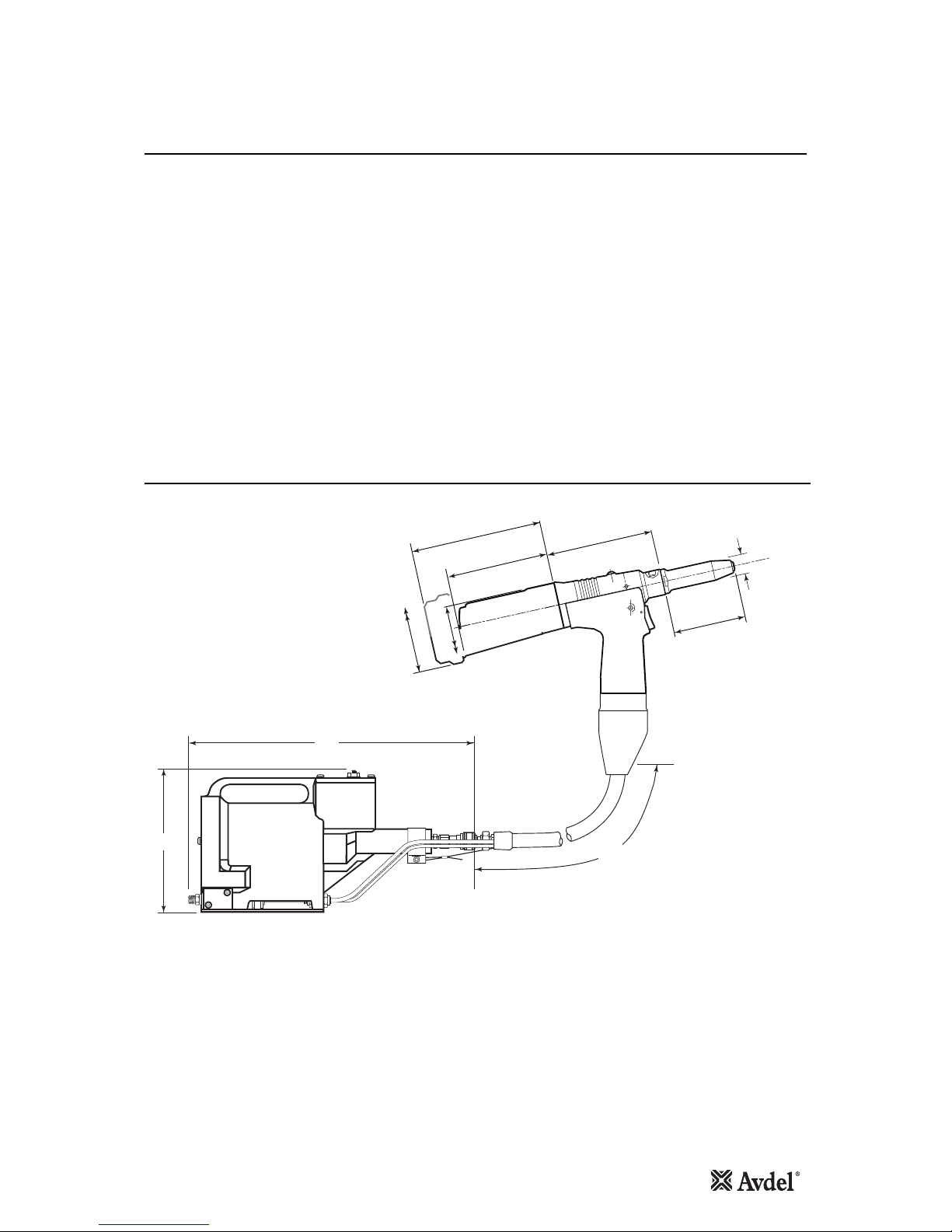
Dimensions in millimetres
71401 and 71404 Tool Dimensions
200
417
127.00 (71401 TOOL)
145.00 (71404 TOOL)
116.00
54.00 DIA
70.00 DIA
(71404 TOOL)
105.00
(71401 TOOL)
22.80
2150
82.30
Tool Specifications

6
Intent of Use
COMPLETE TOOL
71401-00 . . .
71404-00 . . . *
*
BASE TOOL
NOSE ASSEMBLY
NOSE TIP
71401-01000
71404-01000
71213-15000
see note 3 ++=
1
1 2 3
1
2
2
3
3
n
G2s is a hydro-pneumatic tool designed to place Avdel®
breakstem fasteners at high speed making it ideal for batch or
flow-line assembly in a wide variety of applications throughout
all industries. It can place all fasteners listed opposite.
The tool features a vacuum system for fastener retention and
trouble free collection of the spent stems regardless of tool
orientation.
See the ‘Operating Procedure’, page 8, for adjustment
instructions.
A complete tool, except the 71401-00039 or 71404-00039, is
made up of three separate elements which must be ordered
individually.
See diagram below.
If you wish to place most of the fasteners in the table
opposite, you can order the 71401-00039 or 71404-
00039 complete tool comprising:
• 71401-01000 or 71404-01000 base tool.
• 71213-15000 nose assembly.
• Nose tips 71210-05002, 71210-16070 and 07381-
04701.
Fit nose tips as indicated on pages 9 to 12.
The part number of the base tool remains the same whichever nose assembly, or nose tip is fitted. For details of the pistol, see
page 24. If a swivel head is fitted, the same base tool must be adapted. See details pages 14, 15 and 16.
This single nose assembly will allow placing of fasteners by simply selecting the appropriate nose tip from
the range of type 1 nose tips. Other nose assemblies are available for applications with restricted access and
for special fasteners. See tables on pages 10 and 12. A nose assembly can be substituted by a swivel
head (see pages 14 to 16). In this case the nose tip is part of the swivel head.
The nose tip part number relates to a specific fastener. If access to the application is
restricted, some extended nose tips are available. See page 12 for selection table.
* ADD 3 DIGITS FROM THE
LAST COLUMN OF A NOSE TIP
TABLE ON PAGE 10 OR 12.
FOR TOOLS WITH SWIVEL HEADS
USE TABLE ON PAGE 14.
You can order the above three nose tips and nose assembly as a nose assembly kit part number 71213-15100. For some
fasteners, the base tool, nose assembly and nose tip must be ordered separately. NOSE EQUIPMENT MUST BE FITTED AS
DESCRIBED ON PAGE 9.
Part Numbering
FASTENER
NAME
MM
IN
FASTENER SIZE ( )
AVEX®
STAVEX®
AVINOX®II
AVIBULB®
ETR
BULBEX®
T-LOK®
AVDEL®SR
MONOBOLT ®
INTERLOCK®
®
®
KLAMPTITE KTR
KLAMP-TITE
*AVSEAL
Q RIVET
®II
3 3.2 4.0 4.3 4.8 5 5.2 6 6.5 7
–1/85/32 –3/16 –––––
Range of Fasteners
*For Avseal®equipment refer to Data Sheet 07900-00840
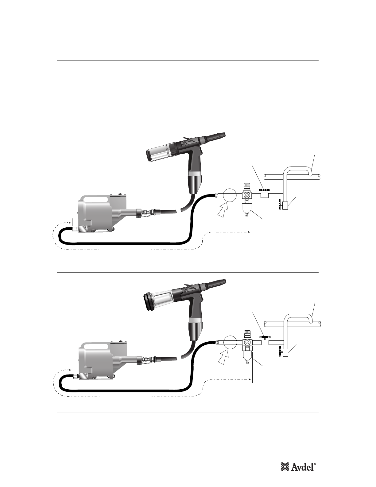
Air Supply
Putting into Service
All tools are operated with compressed air at an optimum pressure of 5.5 bar. We recommend the use of pressure regulators and
filtering systems on the main air supply. These should be fitted within 3 metres of the tool (see diagram below) to ensure maximum
tool life and minimum tool maintenance.
Air supply hoses should have a minimum effective working pressure rating of 150% of the maximum pressure produced in the system
or 10 bar, whichever is the highest. Air hoses should be oil resistant, have an abrasion resistant exterior and should be armoured
where operating conditions may result in hoses being damaged. All air hoses MUST have a minimum bore diameter of 6.4 millimetres
or 1/4inch.
8
6
4
2
0
10
12
14
16
TAKE OFF POINT
FROM MAIN SUPPLY
STOP COCK
(USED DURING MAINTENANCE
OF FILTER/REGULATOR
OR LUBRICATION UNITS)
MAIN SUPPLY
DRAIN POINT
PRESSURE REGULATOR
AND FILTER
(DRAIN DAILY)
3 METRES MAXIMUM
AIR LUBRICATION
PERMISSABLE
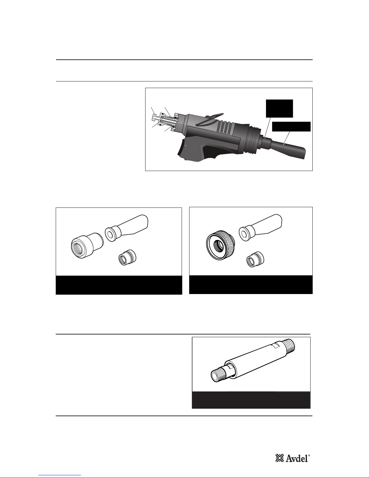
71401 Tool Removable Bottle
71404 Tool Fixed Bottle
7
8
6
4
2
0
10
12
14
16
TAKE OFF POINT
FROM MAIN SUPPLY
STOP COCK
(USED DURING MAINTENANCE
OF FILTER/REGULATOR
OR LUBRICATION UNITS)
MAIN SUPPLY
DRAIN POINT
PRESSURE REGULATOR
AND FILTER
(DRAIN DAILY)
3 METRES MAXIMUM
AIR LUBRICATION
PERMISSABLE
•Using a screwdriver, turn rotary valve 48 until the air flow at the rear of the tool ceases.
•With the nose of the tool pointing downwards, insert a fastener into the nose and hold it into position.
•Turn the rotary valve either way until there is sufficient suction to retain the fastener.
Adjusting the Vacuum Extraction

8
Operating Procedure
Putting into Service
•Ensure that the correct nose assembly suitable for the fastener
is fitted.
•Connect the tool to the air supply.
•Insert the fastener stem into the nose of the tool. If using a
standard nose assembly, the fastener should remain held in by
the vacuum system.
•Bring the tool with the fastener to the application so that the
protruding fastener enters squarely into the hole of the
application.
•Fully actuate the Trigger. The tool cycle will broach the fastener
and with standard nose assemblies the broken stem will be
projected to the rear of the tool into the collector bottle.
•A Quarter turn rotation removes or replaces the collector bottle.
Quarter turn to Assemble
or Remove
Removable Stem Collector Bottle 71213-05100
Do not use tool when Stem
Collector Bottle is removed

9
Fitting Instructions
IMPORTANT
The air supply must be disconnected when fitting or removing nose assemblies.
Item numbers in bold refer to the nose assembly components in all 2 Nose Tip tables on pages 10 and 12.
•Lightly coat Jaws 4with Moly Lithium grease*.
•Drop jaws 4into Jaw Housing 3.
•Insert Jaw Spreader 5into Jaw Housing 3.
•Locate Buffer 6on Jaw Spreader 5.
•Locate Spring 7onto Jaw Spreader 5.
•Insert Detent Sleeve 10 into Jaw Spreader Housing ‘T’ 9. Not applicable to Type 2 Nose Assembly.
•Fit Locking Ring 8onto the Jaw Spreader Housing ‘T’ 9.
•For tools converted to nose assembly Type 2, fit Locking Ring 8 onto the Jaw Spreader Housing ‘T’ 9attached to the tool.
•Tighten Jaw Housing 3and assembled components onto Jaw Spreader Housing ‘T’ 9.
•Utilising the ‘T’ section profiles assemble Nose Assembly onto the tool piston via the Male ‘T’ Adaptor (item 1pages 24-25).
Not applicable to Type 2 Nose Assembly.
•Screw the nose tip into Nose Casing 1and tighten with spanner*.
•Place Nose Casing 1over Jaw Housing 3and screw onto the tool, tightening with spanner*.
Nose assemblies should be serviced at weekly intervals. You should hold some stock of all internal components of the nose assembly
and nose tips as they will need regular replacement.
Use Spanner 07900-00849 (supplied with tool) to assist when servicing the nose assembly.
•Remove the nose equipment using the reverse procedure to the ‘Fitting Instructions’.
•Any worn or damaged part should be replaced.
•Clean and check wear on jaws.
•Ensure that the jaw spreader is not distorted.
•Check Spring 7is not distorted.
•Assemble according to fitting instructions above.
* Item included in the
n
G2s service kit. For complete list see page 20.
Item numbers in bold refer to the nose assembly components in all 2 Nose Tip tables on pages 10 and 12.
Servicing Instructions
Nose Assemblies
10
A tool (except part number 71401-00039 or 71404-00039) must always be fitted with the correct nose assembly and nose tip for
your fastener and must be ordered separately, refer to the ‘NOSE TIPS’ tables below and on page 12.
If your application presents no access restriction use a Type ‘1’ Nose Tip.
Dimensions ‘A’ and ‘B’ below will help you assess the suitability of a particular nose tip.
You should also check that the dimensions of the nose casing will not restrict access to your application. If access is restricted Type
‘2’ Nose Tips are available for some fasteners. Refer to the table on page 12.
It is essential that nose assembly and nose tip are compatible with the fastener prior to operating the tool. If you have ordered a
71401-00039 or 71404-00039 complete tool, it is important that you check that the nose tip already fitted to the nose assembly is
the correct one to place your fastener by sliding the fastener stem into the nose tip. No force should be required and play should be
minimal.
Swivel heads are available as an alternative to nose assemblies when further reach is required. See pages 14 to 16 in the
‘Accessories’ section.
IMPORTANT
Nose assemblies do NOT include nose tips. Nose tips must be ordered separately.
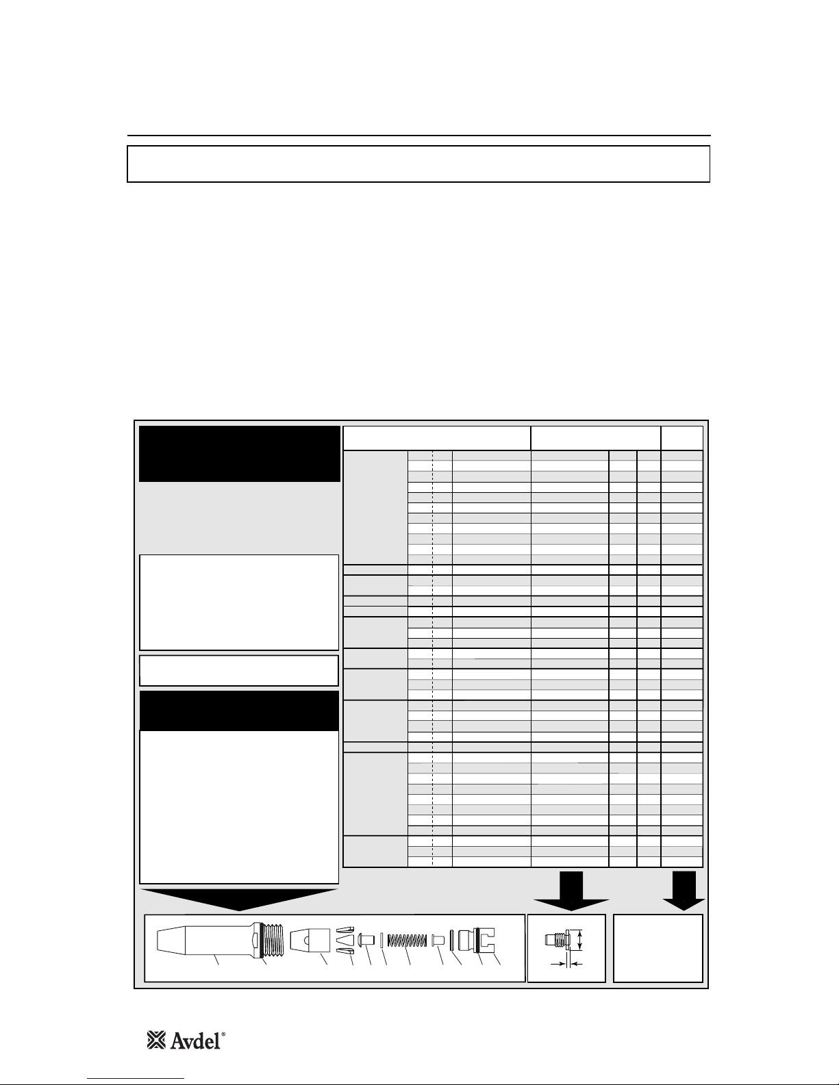
Nose Tips
1
In inches then in millimetres.
2
Head forming nose tips for use with countersunk heads
ONLY.
3
Long nose tip for deep placing.
4
Dome head.
5
Countersunk.
TYPE 1
NOSE TIPS
NOSE ASSEMBLY
part nº 71213-15000
(+ 3 nose tips above = 71213-15100)
FASTENER
MATERIAL
Ø1
NOSE TIP (mm) see
below
PART Nº 'A' 'B'NAME
Al Alloy
Steel
Al Alloy
Al Alloy
Al Alloy
Steel
Al Alloy
Al Alloy
Al Alloy
Steel
Al Alloy
Any
Al Alloy
Al Alloy
Al Alloy
Al Alloy
Stainless Steel
Stainless Steel
Stainless Steel
Steel
Steel
Steel
Steel
Steel
Any
Any
Any
Any
Any
Steel
Steel
Steel
Steel
Steel
Stainless Steel
Stainless Steel
Stainless Steel
Any
Any
Any
1/8
1/8
1/8
–
5/32
5/32
5/32
3/16
3/16
3/16
3/16
3/16
5/32
3/16
3/16
3/16
1/8
5/32
3/16
–
3/16
1/8
5/32
3/16
1/8
5/32
3/16
3/16
3/16
1/8
5/32
3/16
3/16
3/16
1/8
5/32
3/16
1/8
5/32
3/16
4.8
3.3
2.9
4.8
3.3
2.8
3.3
2.8
3.3
3.3
4.1
4.1
3.3
2.8
4.8
2.8
3.3
2.8
4.8
3.3
3.3
3.3
2.8
4.8
4.8
3.3
5.7
5.7
2.8
3.3
2.8
2.8
3.3
2.8
3.3
2.8
2.8
4.8
3.3
3.3
12.7
12.7
12.7
12.7
12.7
12.7
12.7
12.7
19.0
12.7
12.7
12.7
12.7
12.7
12.7
12.7
12.7
12.7
12.7
12.7
12.7
12.7
12.7
12.7
12.7
12.7
12.7
12.7
12.7
12.7
12.7
12.7
19.0
12.7
12.7
12.7
12.7
12.7
12.7
12.7
71210-05002
71210-16070
07340-064012
71210-05002
71210-16070
07381-04701
07340-065012
07381-04701
07340-04800
07490-04401
07340-066012
71210-16020
71210-16070
07381-04701
71220-16060
07381-04701
71210-16070
07381-04701
07498-01401
07340-06201
07340-06201
71210-16070
07381-04701
07498-01401
71210-05002
71210-16070
07348-070014
71210-160505
07381-04701
71210-16070
07381-04701
07381-04701
07340-04800
07381-04701
71210-16070
07381-04701
07381-04701
71210-05002
07340-06201
07340-06201
3.2
3.2
3.2
3.0
4.0
4.0
4.0
4.8
4.8
4.8
4.8
4.8
4.0
4.8
4.8
4.8
3.2
4.0
4.8
4.3
4.8
3.2
4.0
4.8
3.2
4.0
4.8
1.8
4.8
3.2
4.0
4.8
4.8
4.8
3.2
4.0
4.8
3.2
4.0
4.8
AVEX®
Large flange
MONOBOLT ®
BULBEX®
KLAMPTITE
KTR
®
KLAMP-TITE
®
AVINOX®II
T-LOK®
AVIBULB®
AVDEL®SR
INTERLOCK®
STAVEX®
Large flange
Countersunk
Q RIVET
…039*
…039*
…003
…039*
…039*
…039*
…009
…039*
…016
…017
…015
…200
…039*
…039*
…430
…039*
…039*
…039*
…082
…120
…120
…039*
…039*
…082
…039*
…039*
…062
…064
…039*
…039*
…039*
…039*
…016
…039*
…039*
…039*
…039*
…039*
…120
…120
A
B
ITEM DESCRIPTION PART Nº
1 TAPERED NOSE CASING 71213-00350
2 'O' RING 07003-00067
3 JAW HOUSING - TAPERED 71210-15902 *
4 JAW 71210-15001 *
5 JAW SPREADER 07498-04502 *
6 BUFFER 71210-05001 *
7 SPRING 07500-00418 *
8 LOCKING RING 07340-00327 *
9 JAW SPREADER HOUSING 'T' 71210-20321 *
10 DETENT SLEEVE 71210-20322 *
*11 'O' RING 07003-00277
COMPLETE TOOL
PART NUMBER :
precede with 71401-00
or 71404-00
123456710 11 98
* Items 3-11 availabl e as cartridg e assembl y
71213-20320
*Complete tool part number 71401-00039 or
71404-00039 does not only include the
71213-15000 nose assembly below but also the
following three nose tips:
71210-05002, 71210-16070 and 07381-04701
making up a nose assembly kit part number
71213-15100. Use the nose tip listed in the
table.
Nose Assemblies

11
Fitting Type 2 or Nose Extension
To fit Nose Tip Type 2 or Nose Extension, the ‘T’ Adaptor 1must be replaced with Jaw Spreader Housing 9*.
•Loosen Locknut 3 using 16mm AF Spanner.
•Unscrew and remove ‘T’ Adaptor 1together with ‘O’ Ring 2.
12
27
43
3
•Fit Jaw Spreader Housing 9* together with ‘O’ Ring 10* (supplied with Type 2 Nose Assembly).
•The Jaw Spreader Housing 9* must be tightened onto Head Piston 27 trapping Vacuum Sleeve 43 finally tighten
Locknut 3against Jaw Spreader Housing 9*.
9* 10*
27
43
Items 9* and 10* refer to nose assembly components in Nose Tip table on page 12.
For other items in bold refer to the General Assembly drawing and Parts List on pages 24 and 25.
Nose Assemblies
12
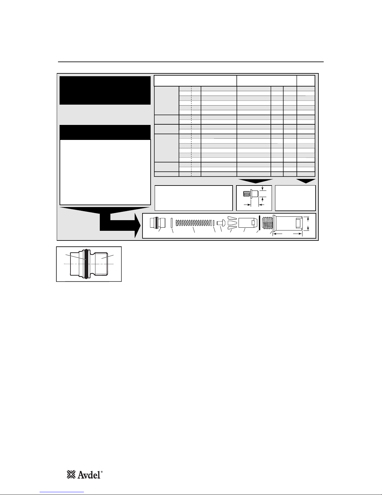
Nose Tips
1
In inches then in millimetres.
COMPLETE TOOL
PART NUMBER :
precede with
71401-00 or
71404-00
NOSE ASSEMBLY
part nº 71210-15200
A
B
TYPE 2 NOSE TIPS ARE EXTENDED
TO ALLOW ACCESS INTO
APPLICATIONS WHERE TYPE 1
NOSE TIPS WILL NOT REACH.
TYPE 2
NOSE TIPS
8 7 6 5 4239 & 10 158.3
22.9
FASTENER
MATERIAL
Ø1
NOSE TIP (mm) see
below
PART Nº 'A' 'B'NAME
Aluminium Alloy
Steel
Aluminium Alloy
Steel
Aluminium Alloy
Steel
Aluminium Alloy
Aluminium Alloy
Steel
Steel
Steel
Steel
Steel
Stainless Steel
Stainless Steel
Stainless Steel
Steel
Steel
Steel/Brass
1/8
1/8
5/32
5/32
3/16
3/16
5/32
3/16
–
3/16
1/8
5/32
3/16
1/8
5/32
3/16
1/8
5/32
–
12.95
11.4
11.4
10.0
10.0
11.8
11.4
10.0
10.0
10.0
11.4
10.0
10.0
11.4
10.0
10.0
11.4
10.0
10.0
9.5
9.5
9.5
12.7
12.7
12.7
9.5
12.7
12.7
12.7
9.5
12.7
12.7
9.5
12.7
12.7
9.5
12.7
12.7
07340-02805
07340-02806
07340-02806
07340-02807
07340-02807
07340-07301
07340-02806
07340-02807
07241-07101
07241-07101
07340-02806
07340-02807
07340-02807
07340-02806
07340-02807
07340-02807
07340-02806
07340-02807
07340-02807
3.2
3.2
4.0
4.0
4.8
4.8
4.0
4.8
4.3
4.8
3.2
4.0
4.8
3.2
4.0
4.8
3.2
4.0
5.2
AVEX®
BULBEX®
T-LOK®
STAVEX®
AVIBULB®
ETR
…002
…008
…008
…014
…014
…018
…008
…014
…121
…121
…008
…014
…014
…008
…014
…014
…008
…014
…014
ITEM DESCRIPTION PART Nº
1 NOSE CASING 07340-02804
2 'O' RING 07003-00067
3 JAW HOUSING 07340-00304
4 JAWS 71210-15001
5 JAW SPREADER 07498-04502
6 BUFFER 71210-05001
7 SPRING 07500-00418
8 LOCKING RING 07340-00327
9 JAW SPREADER HOUSING 71210-02101
10 'O' RING 07003-00277
10 9
Remove Male ‘T’ Adaptor 1from the Tool (see page 11) and replace with
Jaw Spreader Housing 9* (71210-02101) and ‘O’ Ring 10*.
9* and 10* refer to the illustrations on this page.
Nose Assemblies
1
3
27
43
07340-00342
STEM DEFLECTOR
71213-20103
or
71210-20101
ADAPTOR
13
Stem Deflector
Accessories
Item numbers in bold refer to the General Assembly drawing and Parts List on pages 24 and 25.
9* and 10* refers to the nose assembly components in Nose Tip tables on page 12.
Fitted between the tool and the nose assembly the extension
allows access into deep channels.
The tool must be fitted with Jaw Spreader Housing 9*and ‘O’ Ring
10* before the extension can be fitted. See page 11 for fitting
instructions.
•To fit the extension, remove any nose assembly components.
•Screw the inner extension to Jaw Spreader Housing 9*.
•Screw the outer onto Head Assembly 4.
•Fit the nose assembly onto the extension.
INNER OUTER
EXTENSION - 'T' ADAPTOR 71213-12000
EXTENSION - NON QUICK RELEASE 71210-20300
Extension
The airline must be disconnected before any
servicing or dismantling.
‘Sealed’ Nut 71213-02200 replaces Locknut
3(to cut-off air supply to vacuum system) as
follows:
•Loosen Locknut 3using 16mm AF spanner.
•Unscrew and remove Both ‘T’ Adaptor 1
and Locknut 3.
•Replace Locknut 3with ‘Sealed” Nut
71213-02200, screw the ‘Sealed” Nut
onto head Piston 27 to disable the
vacuum system.
•‘T’ Adaptor 1must be tightened onto
Head Piston 27 to trap Vacuum Sleeve
43 against the head piston, finally
tightening the ‘Sealed’ Nut against it.
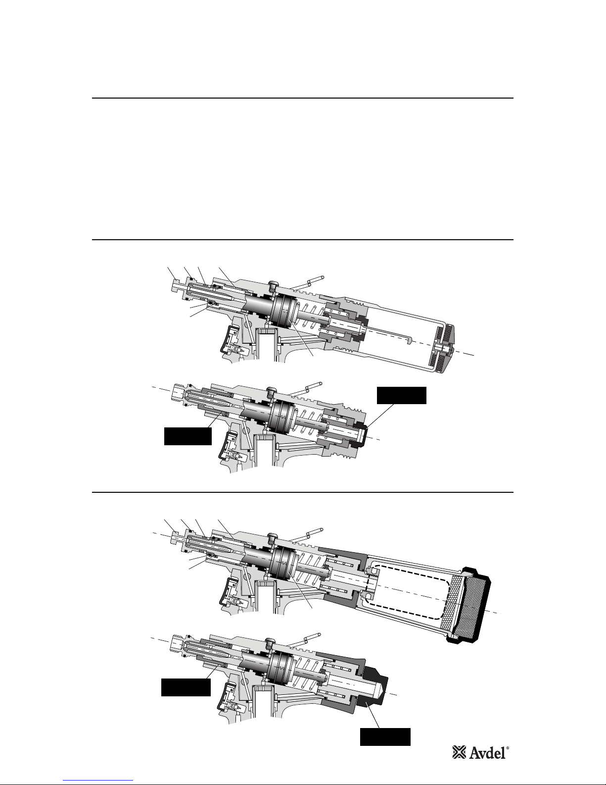
Preparing the Base Tool for use with Stem Deflector
The stem deflector is a very simple alternative to the standard stem collector and allows access in restricted areas. To replace the
stem collector with the stem deflector proceed as follows:
Swivel Heads
Instead of a nose assembly, a swivel head can be fitted to a base tool. It allows 360° rotation of the tool about the nose tip and
allows access into many applications otherwise too restrictive. There are two types of swivel heads: the straight swivel head with
the nose tip slightly offset from the centre line of the tool head and the right-angle swivel head with the nose tip on a perpendicular
axis to the head of the tool. See drawings below and page 14 for dimensions and page 15 for details.
ADAPTOR NUT
71210-20101
STEM DEFLECTOR
07340-00342
SEALED NUT
71213-02200
STEM DEFLECTOR
71404 Tool
ADAPTOR
71213-20103
STEM DEFLECTOR
07340-00342
SEALED NUT
71213-02200
STEM DEFLECTOR: 71213-20100
71401 Tool
•Fit Stem Deflector (07340-00342) into Adaptor (71213-20103).
•Screw Adaptor onto End Cap Assembly 71213-05103.
•Rotate the stem deflector until the aperture faces away from the
operator and any other person(s) in the vicinity.
•Fit Stem Deflector (07340-00342) into Adaptor (71210-
20101).
•Screw Adaptor onto End Cap Assembly 71403-02102.
•Rotate the stem deflector until the aperture faces away from
the operator and any other person(s) in the vicinity.

14
FASTENER
MATERIAL
Ø1
NOSE TIP (mm)SWIVEL HEAD
PART Nº
JAWS see
below
'A' 'B'NAME
Aluminium Alloy
Steel
Aluminium Alloy
Steel
Aluminium Alloy
Aluminium Alloy
Aluminium Alloy
Stainless Steel
Stainless Steel
Aluminium Alloy
Aluminium Alloy
Aluminium Alloy
Aluminium Alloy
Steel
Steel
Stainless Steel
Stainless Steel
1/8
1/8
5/32
5/32
3/16
5/32
3/16
1/8
5/32
–
–
–
–
1/8
5/32
1/8
5/32
3.81
3.81
3.81
3.81
3.81
3.81
3.81
3.81
3.81
1.95
4.11
2.00
4.11
3.81
3.81
3.81
3.81
7.87
7.87
7.87
7.87
7.87
7.87
7.87
7.87
7.87
6.35
6.35
7.62
7.62
7.87
7.87
7.87
7.87
07346-03000
07346-03100
07346-03100
07346-03200
07346-03200
07346-03100
07346-03200
07346-03100
07346-03200
71213-04000
71213-04700
71213-04100
71213-04800
PART Nº
07340-00213
07340-00213
07340-00213
07490-04602
07490-04602
07340-00213
07490-04602
07340-00213
07490-04602
07340-00213
07340-00213
07340-00213
07340-00213
07340-00213
07490-04602
07340-00213
07490-04602
PART Nº
07345-03600
07345-03700
07345-03700
07345-03800
07345-03800
07345-03700
07345-03800
07345-03700
07345-03800
71213-16401
71213-164022
71213-16403
71213-164042
07345-03700
07345-03800
07345-03700
07345-03800
3.2
3.2
4.0
4.0
4.8
4.0
4.8
3.2
4.0
3.2
4.0
3.2
4.0
AVEX®
BULBEX®
AVINOX® II
AVSEAL®II
STAVEX®
…001
…004
…004
…010
…010
…004
…010
…004
…010
…160
…180
…161
…181
…004
…010
…004
…010
RIGHT-ANGLE SWIVEL HEAD capability
1 In inches then in millimetres. 2 Long nose tip for deep placing.
COMPLETE TOOL PART NUMBER :
precede with 71401-40 or 71404-40
(the stop nut and safety cap are included)
IMPORTANT: in contrast to complete tools
with nose assemblies, those fitted with swivel
heads include the nose tip as a part of the head.
7.6
32
20
52
56
74
97
A
B
360
o
rotation
07346-03100
07346-03200
07346-03100
07346-03200
4.0
4.0
5.0
5.0
Swivel Heads
Accessories
1
In inches then in millimetres.
2
Long nose tip for deep placing.
FASTENER
MATERIAL
Ø1
NOSE TIP (mm)SWIVEL HEAD
PART Nº
JAWS see
below
'A' 'B'NAME
Al Alloy
Steel
Al Alloy
Steel
Al Alloy
Al Alloy
Al Alloy
Stainless Steel
Stainless Steel
Al Alloy
Al Alloy
Al Alloy
Al Alloy
Steel
Steel
Stainless Steel
Stainless Steel
1/8
1/8
5/32
5/32
3/16
5/32
3/16
1/8
5/32
–
–
–
–
1/8
5/32
1/8
5/32
3.81
3.81
3.81
3.81
3.81
3.81
3.81
3.81
3.81
1.95
4.11
2.00
4.11
3.81
3.81
3.81
3.81
7.87
7.87
7.87
7.87
7.87
7.87
7.87
7.87
7.87
6.35
6.35
7.62
7.62
7.87
7.87
7.87
7.87
07345-03000
07345-03100
07345-03100
07345-03200
07345-03200
07345-03100
07345-03200
07345-03100
07345-03200
71213-06000
71213-06600
71213-06100
71213-06700
07345-03100
07345-03200
07345-03100
07345-03200
PART Nº
07340-00213
07340-00213
07340-00213
07490-04602
07490-04602
07340-00213
07490-04602
07340-00213
07490-04602
07340-00213
07340-00213
07340-00213
07340-00213
07340-00213
07490-04602
07340-00213
07490-04602
PART Nº
07345-03600
07345-03700
07345-03700
07345-03800
07345-03800
07345-03700
07345-03800
07345-03700
07345-03800
71213-16401
71213-164022
71213-16403
71213-164042
07345-03700
07345-03800
07345-03700
07345-03800
3.2
3.2
4.0
4.0
4.8
4.0
4.8
3.2
4.0
4.0
4.0
5.0
5.0
3.2
3.2
3.2
4.0
AVEX®
BULBEX®
AVINOX® II
AVSEAL®II
STAVEX®
…001
…004
…004
…010
…010
…004
…010
…004
…010
…160
…180
…161
…181
…004
…010
…004
…010
COMPLETE TOOL PART NUMBER :
precede with 71401-30 or 71404-30
(the stop nut and safety cap are included)
IMPORTANT: in contrast to complete tools
with nose assemblies, those fitted with swivel heads
include the nose tip as a part of the head.
STRAIGHT SWIVEL HEAD capability
A
B
360orotation
56 92
6
20
IMPORTANT
PRIOR to fitting a swivel head, the base tool must be adapted. See Preparing the Base Tool page 14.
In contrast to nose assemblies part numbers of swivel heads do INCLUDE a nose tip as shown below.
Swivel heads can be ordered on their own or supplied with a base tool. See table below for part numbers. Jaws and nose tips vary
depending on the fastener to be placed but all other components remain the same within each type of swivel head. See the ‘capability’
tables below and page 14 and the ‘Constant Components ‘ table page 16.
'A’ and ‘B’ dimensions will help you assess the accessibility of your application.
Remove Male ‘T’ Adaptor 1from the Tool (see page 10) and replace with
Jaw Spreader Housing (71210-02101).
1 2 3 5
42
41
27
71213-20200
STOP NUT
71213-20102
SAFETY CAP
15
Preparing the Base Tool for Right-Angle and Straight Swivel Head Attachment
Accessories
•Disconnect the air supply.
•Remove any nose assembly items.
•Remove Stem Collector Bottle Assembly 20 (71213-03800).
•Replace assembly 20 with Safety Cap (71213-20201).
•Unscrew Male ‘T’ Adaptor 1and remove with ‘O’ Ring 2, Locknut 3, ‘O’ Rings 42 and 41, and Seal Housing 5. Do not refit these
items.
•Screw Stop Nut (71213-20200) onto the front of Head Piston 27 as far as it will go by hand.
•Fit Jaw Spreader Housing (71210-02101) and ‘O’ Ring 2, tighten onto Head Piston 27, finally tighten Stop Nut against Jaw
Spreader Housing.
The tool is now ready to be fitted with a swivel head. Instructions page 16.
Item numbers in bold refer to the general assembly drawing and parts list on pages 24-25.
Base tool to receive a nose assembly
Base tool to receive a swivel head
Base Tool 71401
Base Tool 71404
1 2 3 5
42
41
27
71213-20202
STOP NUT
71210-20201
SAFETY CAP
Base tool to receive a nose assembly
Base tool to receive a swivel head
16
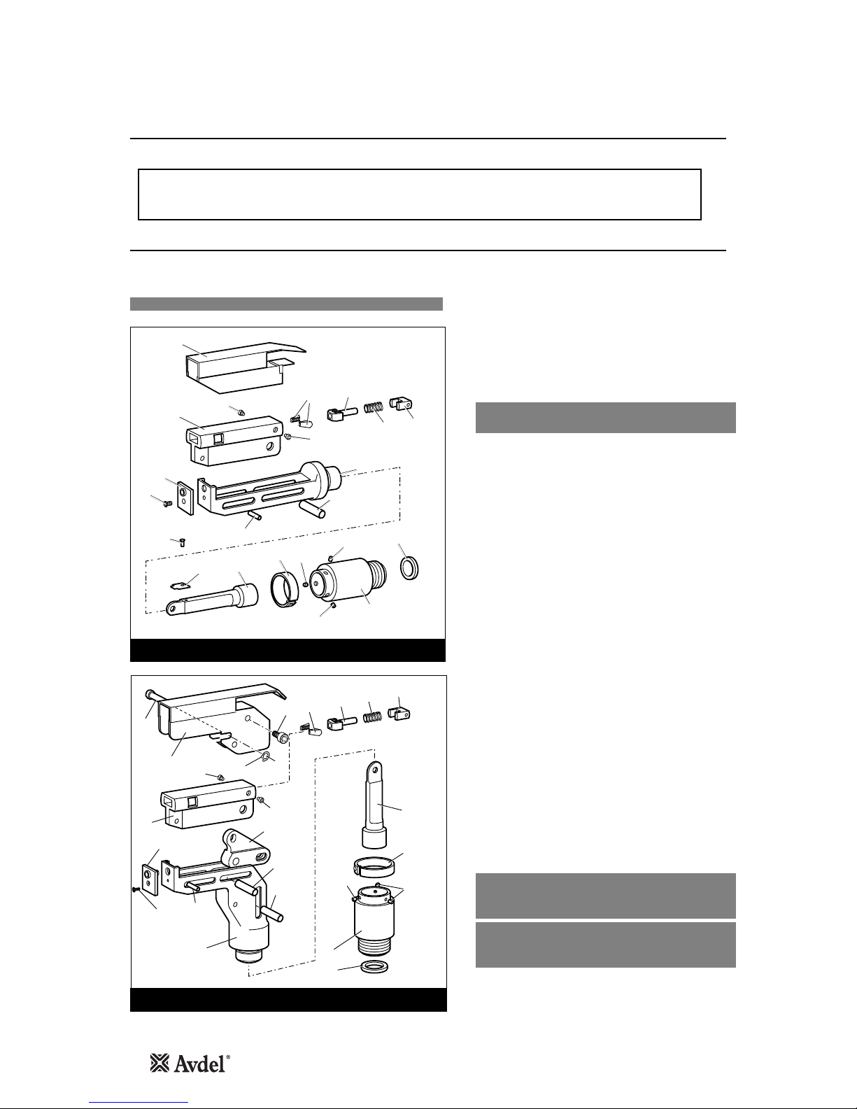
Straight and Right-Angle Heads
Fitting Instructions
Accessories
The following procedure will allow you to assemble and fit either of the swivel heads to the tool. If you order a complete swivel head
rather than individual components, you will only need to start at stage L.
All moving parts should be lubricated. Unless stated otherwise use MolyLithium grease (details page 18).
When on grey tint, instructions refer only to the right-angle swivel head. Item numbers in bold refer to illustrations below.
IMPORTANT
PRIOR to fitting a swivel head, the base tool must be adapted. See previous page.
The air supply must be disconnected when fitting or removing swivel heads.
The fitting and servicing procedures for both types of head are almost identical. Differences are clearly indicated.
2
1
15
9
8
8
10
7
11
17
23 18 19 20
316
16
4
12
14
13
6
6
5
RIGHT-ANGLE HEAD
16
1
3
12
14
13
16
6
5
21
22 11
7
9
8
8
8
10
17 18
19 20
STRAIGHT SWIVEL HEAD
Item numbers in bold refer to illustrations on this page.
9* refers to 71210-02101 Jaw Spreader Housing.
AFit Locking Ring 10 over Jaw Spreader Housing 9*.
BCoat Screw 13 with thread locking adhesive and use to
secure Nose Tip 14 onto Body 5.
CLightly lubricate items 17, 18, 19, 20 and insert into Jaw
Carrier 3 as shown. Secure with Screws 16.
DPosition Lever 4into Body 5and hold in place with Pin 15
through the hole of Body 5(not a slot).
ELubricate the sides of the jaw carrier assembly and insert
into Body 5.
FLubricate Rollers 8and ENSURE that they will freely rotate in
the holes of Adaptor 9. If necessary ream the holes.
GPosition Spring Clip 7over Adaptor 9past the holes for the
rollers and rotate until the locating peg is aligned with the
corresponding hole in Adaptor 9(smallest hole).
HFit Adaptor 9over the end of Body 5and drop Rollers 8into
place. Push Spring Clip 7over Rollers 8.
IInsert Spindle 11 through Adaptor 9into Jaw Carrier 3until
the hole lines up with slot in Body 5. Temporarily hold in
place with Pin 6.
JInsert Pin 12 through the front slot of Body 5into Jaw
Carrier 3.
KHold the assembly vertical to prevent all pins dropping and
slide the jaw carrier assembly back and forth a few times to
ensure free movement. Go to M.
LRemove Screws 23 (4 off) and Guard 1. On a straight swivel
head also remove Screw 21 and Platform 22.
MPush Pin(s) 6out and let Spindle 11 drop out. Screw Spindle
11 onto the jaw spreader housing of the tool, leaving the
small screw fixing hole uppermost for straight swivel.
Tighten gently with a tommy bar.
NScrew the assembly over Spindle 11 onto the tool handle.
Replace Pin(s) 6.
OOn straight swivel heads attach Platform 22 onto the top of
the spindle with Screw 21. Deburr the back end of Platform
22 so that it cannot catch on Guard 1.
PSnap Guard 1over the assembly, align screw holes in guard
with tapped holes in body assembly.
QInsert Pivot Pin 15 through slots in guard and hole in body.
Fit Circlip 2onto pivot pin so that the circlip seats in
groove provided.
RCoat the thread of Screws 23 (4 off) with thread locking
adhesive and screw into body assembly securing guard to
body assembly.
17
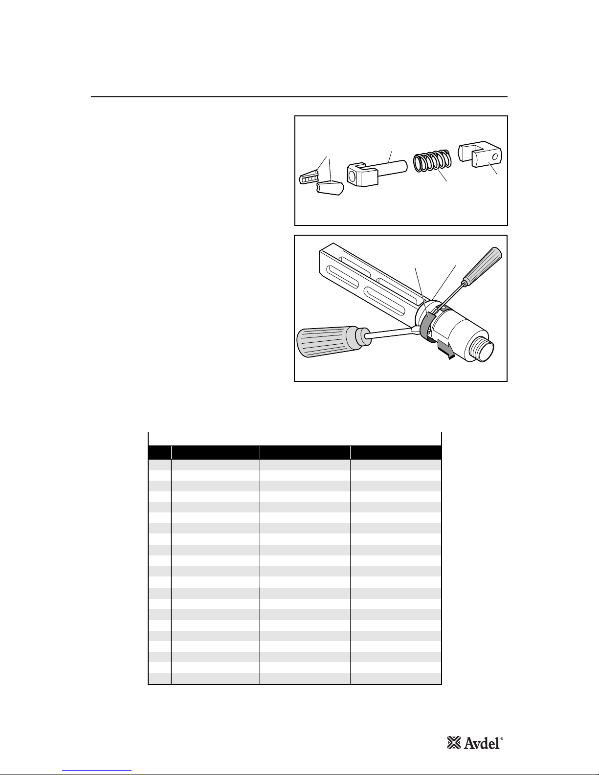
Servicing Instructions
Accessories
5
7
17 18
19 20
Swivel heads should be serviced at weekly intervals.
•Remove the complete head using the reverse procedure to
the ‘Fitting instructions’ omitting step ‘L’ on page 16.
•If Guard 1* is at all damaged it must be replaced by a new
one.
•Any worn or damaged parts should be replaced.
•Pay particular attention to jaw carrier items in the upper
illustration opposite as follows:
Check wear on Jaws 17.
Check that Jaw Spreader Tube 18 is not distorted.
Check that Spring 19 is neither broken or distorted.
Check that Spring Guide 20 is not damaged.
•Check that Spring Clip 7is not distorted. When removing
Spring Clip 7, use two screwdrivers as shown in the lower
illustration opposite.
•Check for excessive wear on slots of Body 5.
•Assemble according to fitting instructions on page 16.
1* refers to item on page 16.
While nose tips and jaws will vary for each swivel head, other components remain constant within each type of head.
See table below. For nose tips and jaws part numbers see pages 10 and 12.
Item numbers in bold refer to illustrations on this page and page 16.
STRAIGHT SWIVEL RIGHT-ANGLE SWIVELITEM DESCRIPTION
CONSTANT COMPONENTS
1GUARD
2CIRCLIP
3JAW CARRIER
4LEVER
5BODY
6 PIVOT PIN
7SPRING CLIP
8ROLLER
9ADAPTOR
10 LOCKING RING
11 SPINDLE
12 DOWEL PIN
07495-03003
07004-00105
07494-03026
07495-03004
07495-03002
07343-02207
07495-03900
07007-00039
07345-03001
07345-03003
07345-03002
07007-00038
07494-05000
-
07494-03026
-
07494-03015
07343-02207
07495-03900
07007-00039
07345-03001
07345-03003
07345-03002
07007-00038
13 SCREW
15 PIVOT PIN
16 SCREW
18 JAW SPREADER
19 SPRING
20 SPRING GUIDE
21 SCREW
22 PLATFORM
23 SECURING SCREW (4OFF)
07342-02207
07346-03102
07494-03028
07346-03101
07165-00305
07494-03027
-
-
07210-00804
07342-02207
-
07494-03028
07346-03101
07165-00305
07494-03027
07001-00368
07345-00401
-

18
Daily
Weekly
MolyLithium Grease EP 3753 Safety Data
Servicing the Tool
IMPORTANT
Read safety instructions on page 4.
The employer is responsible for ensuring that tool maintenance instructions are given to the appropriate personnel.
The operator should not be involved in maintenance or repair of the tool unless properly trained.
The tool shall be examined regularly for damage and malfunction.
•Daily, before use or when first putting the tool into service, pour a few drops of clean, light lubricating oil into the air inlet of the tool if no
lubricator is fitted on air supply.
•Check for air leaks. If damaged, hoses and couplings should be replaced.
•If there is no filter on the pressure regulator, bleed the air line to clear it of accumulated dirt or water before connecting the air hose to the
tool. If there is a filter, drain it.
•Check that the nose assembly or swivel head is correct for the fastener to be placed.
•Check the stroke of the tool meets the minimum specification (page 5). The last step of the Priming Procedure on page 31 explains how to
measure the stroke.
•Either a stem collector or a stem deflector must be fitted to the tool unless using a swivel head is fitted.
•Ensure that Rotary Valve 48 is correctly adjusted for fastener retention (see ‘Operating Procedure’ page 8).
•Stem Collector Bottle: ‘O’ Rings 17 and 23 to be checked for wear, cleaned and lubricated with Molykote®55m.
•Dismantle and clean the nose assembly with special attention to the jaws. Lubricate with MolyLithium grease before assembling.
•Check for oil leaks and air leaks in the air supply hose and fittings.
•Top up the reservoir of the intensifier with hydraulic oil.
Grease can be ordered as a single item, the part number is shown in the Service Kit page 20.
First Aid
SKIN:
As the grease is completely water resistant it is best removed with an approved emulsifying skin cleaner.
INGESTION:
Ensure the individual drinks 30ml Milk of Magnesia, preferably in a cup of milk.
EYES:
Irritant but not harmful. Irrigate with water and seek medical attention.
Fire
FLASH POINT: Above 220°C.
Not classified as flammable.
Suitable extinguishing media: CO2, Halon or water spray if applied by an experienced operator.
Environment
Scrape up for burning or disposal on approved site.
Handling
Use barrier cream or oil resistant gloves
Storage
Away from heat and oxidising agent.
Item numbers in bold refer to the General Assembly drawing and Parts List on pages 24 and 25.

19
Molykote®111 Grease Safety Data
Molykote®55m Grease Safety Data
Servicing the Tool
First Aid
SKIN:
Flush with water. Wipe off.
INGESTION:
No first aid should be needed.
EYES:
Flush with water.
Fire
FLASH POINT: Above 101.1°C. (closed cup)
Explosive Properties: No
Suitable Extinguishing Media: Carbon Dioxide, Foam, Dry Powder or fine water spray.
Water can be used to cool fire exposed containers.
Environment
Do not allow large quantities to enter drains or surface waters.
Methods for cleaning up: Scrape up and place in suitable container fitted with a lid. The spilled product produces an extremely
slippery surface.
Harmful to aquatic organisms and may cause long-term adverse effects in the aquatic environment. However, due to the physical
form and water - insolubility of the product the bioavailability is negligible.
Handling
General ventilation is recommended. Avoid skin and eye contact.
Storage
Do not store with oxidizing agents. Keep container closed and store away from water or moisture.
First Aid
SKIN:
No first aid should be needed.
INGESTION:
No first aid should be needed.
EYES:
No first aid should be needed.
INHALATION:
No first aid should be needed.
Fire
FLASH POINT: Above 101.1°C. (closed cup)
Explosive Properties: No
Suitable Extinguishing Media: Carbon Dioxide, Foam, Dry Powder or fine water spray.
Water can be used to cool fire exposed containers.
Environment
No adverse effects are predicted.
Handling
General ventilation is recommended. Avoid eye contact.
Storage
Do not store with oxidizing agents. Keep container closed and store away from water or moisture.

20
Service Kit
Servicing the Tool
IMPORTANT
Read Safety Instructions on page 4.
The employer is responsible for ensuring that tool maintenance instructions are given to the appropriate personnel.
The operator should not be involved in maintenance or repair of the tool unless properly trained.
The tool shall be examined regularly for damage and malfunction.
For an easy complete service, Avdel offers the complete Service Kit below.
The air line must be disconnected before any servicing or dismantling is attempted unless specifically instructed otherwise.
It is recommended that any dismantling operation be carried out in clean conditions.
Before proceeding with dismantling, empty the oil from the tool following the first three steps of the ‘Priming Procedure’ on page 31.
Prior to dismantling the tool it is necessary to remove the nose equipment. For instructions see the nose assemblies section, pages 9
to 12 or if a swivel head was fitted pages 14 to 16.
For a complete service of the tool, we advise that you proceed with dismantling of sub-assemblies in the order shown.
After any dismantling REMEMBER to prime the tool and to fit an appropriate nose assembly or swivel head.
(Annually or every 500,000 cycles whichever is the soonest)
Annually or every 500,000 cycles the tool should be completely dismantled and new components should be used where worn, damaged
or recommended. All ‘O’ rings and seals should be renewed and lubricated with Molykote®55m grease for pneumatic sealing or
Molykote® 111 for hydraulic sealing.
Maintenance
•Unscrew Nose Casing 1 and Nose Tip.
•Remove the Nose Equipment Cartridge by sliding in the same plane to the Piston.
•Unscrew Jaw Housing 3from the Jaw Spreader Housing ‘T’ 9and remove Jaws 4, Jaw Spreader 5, Spring 7, Buffer 6and Detent
Sleeve 10.
•Inspect all components. Renew all damaged or worn parts.
•Clean all parts and apply Moly Lithium grease EP 3753 (07992-00020) to taper bore of Jaw Housing.
•Reassemble in reverse order to above.
Item numbers in bold refer to Nose Tip Tables on pages 10 and 12.
Nose Equipment
PART Nº DESCRIPTIONPART Nº DESCRIPTION
SERVICE KIT : 07900-00716 Spanners are specified in inches and across flats unless otherwise stated
07900-00008 7/16" x 1/2" SPANNER
07900-00012 9/16" x 5/8" SPANNER
07900-00015 5/8" x 11/16" SPANNER
07900-00157 CIRCLIP PLIERS
07900-00469 2.5 MM ALLEN KEY
07900-00667 PISTON SLEEVE
07900-00670 PISTON BULLET
07900-00672 'T' SPANNER
07900-00677 SEAL EXTRACTOR
07900-00684 GUIDE TUBE
07900-00685 INSERTION ROD
07900-00692 TRIGGER VALVE EXTRACTOR
07900-00158 2 MM PIN PUNCH
07992-00020 GREASE - MOLY LITHIUM E.P.3753
07900-00013 1/8" ALLEN KEY
07900-00714 NON RETURN VALVE ASSEMBLY
07900-00717 SPANNER FOR INTENSIFIER
07900-00224 4 MM ALLEN KEY
07900-00225 5 MM ALLEN KEY
07900-00521 1/4" DIA ROD
This manual suits for next models
1
Table of contents
Other Avdel Power Tools manuals


Avdel
Avdel Genesis G2LB User manual

Avdel
Avdel 0727 User manual

Avdel
Avdel Avbolt 07220 User manual

Avdel
Avdel GenesisG2-s User manual

Avdel
Avdel Genesis G2LB User manual

Avdel
Avdel Genesis G3 HD User manual

Avdel
Avdel G3LB Tool User manual

Avdel
Avdel 7432 User manual

Avdel
Avdel Genesis G4 HD Heavy Duty User manual

Avdel
Avdel 74100 User manual


