Avdel 74405 User manual

Hydro-Pneumatic Power Tool
74405
Instruction Manual
Original Instruction


3
Contents
Safety Instructions 4
Specifications
Tool Specification for 74405 5
Tool Specification for Intensifier 5
Tool Dimensions 5
Intent of Use 6
Putting into Service
Air Supply 7
Operating Procedure 7
Stroke Adjustment 8
Nose Assemblies
Fitting Instructions 9
Servicing Instructions 10
Nose Assembly Components 10
Servicing the Tool
Servicing 11
Daily / Weekly 11
Service Kit 11
Moly Lithium Grease EP 3753 Safety Data 12
Maintenance 13
Head Assembly 13
Air Motor Assembly 14
Handle and Trigger Assembly 14
Intensifier 15
General Assemblies and Parts Lists
Head Assembly General Assembly 16
Head Assembly Parts List 17
Intensifier General Assembly 18
Intensifier Parts List 19
Hand Tool General Assembly and Parts List 20
Priming
Oil Details 21
Hyspin®VG 32 Oil Safety Data 21
Priming Procedure 22
Fault Diagnosis
Symptom, Possible Cause and Remedy 23-24
LIMITED WARRANTY
Avdel makes the limited warranty that it’s products will be free of defects in workmanship and materials
which occur under normal operating conditions. This Limited Warranty is contingent upon: (1) the product
being installed, maintained and operated in accordance with product literature and instructions, and (2)
confirmation by Avdel of such defect, upon inspection and testing. Avdel makes the foregoing limited
warranty for a period of twelve (12) months following Avdel’s delivery of the product to the direct purchaser
from Avdel. In the event of any breach of the foregoing warranty, the sole remedy shall be to return the
defective Goods for replacement or refund for the purchase price at Avdel’s option. THE FOREGOING
EXPRESS LIMITED WARRANTY AND REMEDY ARE EXCLUSIVE AND ARE IN LIEU OF ALL OTHER WARRANTIES
AND REMEDIES. ANY IMPLIED WARRANTY AS TO QUALITY, FITNESS FOR PURPOSE, OR MERCHANTABILITY
ARE HEREBY SPECIFICALLY DISCLAIMED AND EXCLUDED BY AVDEL.
Avdel UK Limited policy is one of continuous product development and improvement and we reserve the right to change the specification of any product without prior notice.

4
Safety Rules
1Do not use outside the design intent.
2Do not use equipment with this tool/machine other than that recommended and supplied by Avdel UK Limited.
3Any modification undertaken by the customer to the tool/machine, nose assemblies, accessories or any equipment supplied by Avdel
UK Limited or their representatives, shall be the customer’s entire responsibility. Avdel UK Limited will be pleased to advise upon any
proposed modification.
4The tool/machine must be maintained in a safe working condition at all times and examined at regular intervals for damage and
function by trained competent personnel. Any dismantling procedure shall be undertaken only by personnel trained in Avdel UK
Limited procedures. Do not dismantle this tool/machine without prior reference to the maintenance instructions. Please contact Avdel
UK Limited. with your training requirements.
5The tool/machine shall at all times be operated in accordance with relevant Health and Safety legislation. In the U.K. the “Health and
Safety at Work etc. Act 1974” applies. Any question regarding the correct operation of the tool/machine and operator safety should
be directed to Avdel UK Limited.
6The precautions to be observed when using this tool/machine must be explained by the customer to all operators.
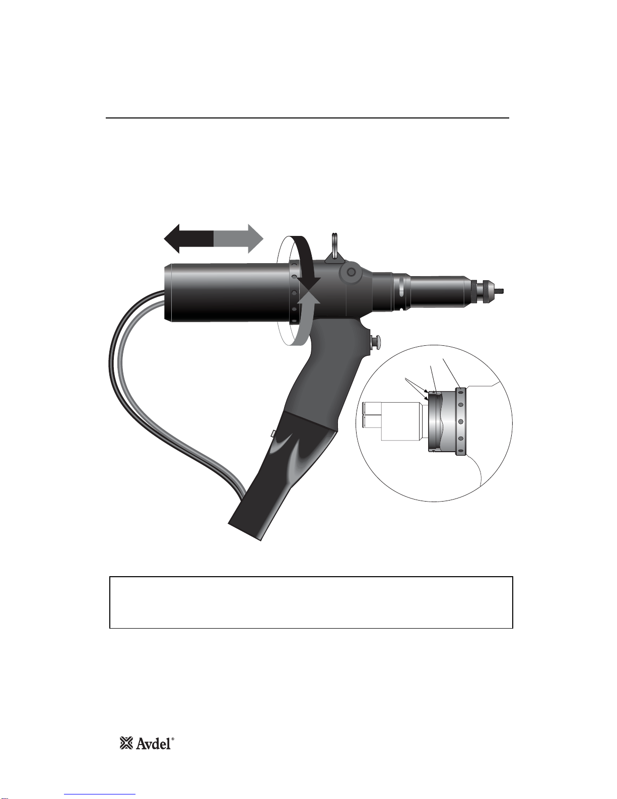
7Always disconnect the airline from the tool/machine inlet before attempting to adjust, fit or remove a nose assembly.
8Do not operate a tool/machine that is directed towards any person(s) or the operator.
9Always adopt a firm footing or a stable position before operating the tool/machine.
10 Ensure that vent holes do not become blocked or covered.
11 The operating pressure shall not exceed 7 bar.
12 Do not operate the tool if it is not fitted with a complete nose assembly or swivel head unless specifically instructed otherwise.
13 Care shall be taken to ensure that spent stems are not allowed to create a hazard.
14 If the tool is fitted with a stem collector, it must be emptied when half full.
15 If the tool is fitted with a stem deflector, it should be rotated until the aperture is facing away from the operator and other person(s)
working in the vicinity.
16 When using the tool, the wearing of safety glasses is required both by the operator and others in the vicinity to protect against
fastener ejection, should a fastener be placed ‘in air’. We recommend wearing gloves if there are sharp edges or corners on the
application.
17 Take care to avoid entanglement of loose clothes, ties, long hair, cleaning rags etc. in the moving parts of the tool which should be
kept dry and clean for best possible grip.
18 When carrying the tool from place to place keep hands away from the trigger/lever to avoid inadvertent start up.
19 Excessive contact with hydraulic fluid oil should be avoided. To minimize the possibility of rashes, care should be taken to wash
thoroughly.
20 C.O.S.H.H. data for all hydraulic oils and lubricants is available on request from your tool supplier.
This instruction manual must be read with particular attention to the following safety rules, by any person
installing, operating, or servicing this tool.

Tool Specification for 74405
Specifications
5
Air Pressure Minimum - Maximum 5-7 bar 60 - 100 lbf/in2
Free Air Volume Required @ 5.5 bar or 75 lbf/in215 litres .525 ft2
Stroke Maximum 16 mm .63 in
Motor Speed SPIN ON 2000 RPM
SPIN OFF 2000 RPM
Pull Force @ 5.5 bar or 75 lbf/in213.84 kN 3111 lbf
Cycle Time Approximately 3 seconds
Noise Level Less than 75 dB(A)
Weight Without equipment or hose 2 kg 4.4 lb
Vibration Less than 2.5 m/s2
Tool Specification for Intensifier
Air Pressure Minimum - Maximum 5-7 bar
Free Air Volume Required @ 5.5 bar or 75 lbf/in23.6 litres
Noise Level Less Than 75 dB(A)
300
445
326
250
35
200
120 102
300 66
Tool Dimensions
Dimensions in millimetres

6
Intent of Use
The hydro-pneumatic 74405 tool is designed to place Avdel® Threaded Inserts at high speed making it ideal for batch or flow-line
assembly in a wide variety of applications throughout all industries.
A complete tool is made up of two seperate elements which will be supplied individually:
•Base Tool - 74405-01000
•Nose Assembly - see datasheet 07900-00857

Air Supply
Putting into Service
7
All tools are operated with compressed air at an optimum pressure of 5.5 bar. We recommend the use of pressure regulators and
filtering systems on the main air supply. These should be fitted within 3 metres of the tool (see diagram below) to ensure
maximum tool life and minimum tool maintenance.
Air supply hoses should have a minimum effective working pressure rating of 150% of the maximum pressure produced in the system
or 10 bar, whichever is the highest. Air hoses should be oil resistant, have an abrasion resistant exterior and should be armoured where
operating conditions may result in hoses being damaged. All air hoses MUST have a minimum bore diameter of 6.4 millimetres or 1/4
inch.
Read servicing daily details page 11.
Follow the steps below when connecting the tool to the intensifier and main air supply:
•Push the end of the large hydraulic hose from the tool into the quick release connector on the end of the intensifier.
•On the front face of the intensifier (Refer to page 18):
•Push the black pneumatic (4mm OD) line into the reducer fitting which is located in the left hand bulkhead connector.
•Push the blue pneumatic (4mm OD) line into the plastic collet of the right hand bulkhead connector.
•On the top face of the control box (Refer to page 20):
•Push the blue pneumatic (6mm OD) line into the reducer labelled ‘Air Motor Spin On’ on the top face of the control box - LH side.
•Push the black pneumatic (6mm OD) line into the reducer labelled ‘Air Motor Spin Off’ on the top face of the control box - middle.
•Push the black pneumatic (4mm OD) line from the flexible hose assembly into the reducer labelled ‘Aux Spin Off’ on the top face
of the control box - RH side.
•Push the black pneumatic (4mm OD) line from the reducer fitting on the intensifier into the reducer labelled ‘Intensifier Timer’ on
the top face of the control box.
•Fit a pneumatic hose between the male connector at the rear of the intensifier and main air supply.
8
6
4
2
0
10
12
14
16
TAKE OFF POINT
FROM
MAIN SUPPLY
STOP COCK
(USED DURING MAINTENANCE
OF FILTER/REGULATOR OR LUBRICATION UNITS)
MAIN SUPPLY
DRAIN POINT
AIR LUBRICATION PRESSURE REGULATOR
AND FILTER (DRAIN DAILY)
3 METRES MAXIMUM
Operating Procedure
•Before you use the tool, remove the Screw 3* on top of the oil reservoir of the intensifier to allow venting. Replace screw when
transporting the intensifier.
•Ensure that a nose assembly suitable for the fastener is fitted (see separate nose assembly data sheet 07900-00857).
•Connect the tool to the intensifier and the intensifier to the air supply.
•Offer up insert, lip first to the drive screw. A light pressure will start the motor and automatically thread the insert up against the
nose and stop.
•Insert the fastener into the application squarely.
•Fully depress the trigger. This will both place the insert into the application and reverse it off the drive screw.
* Item number refers to Intensifier general assembly and parts list on pages 18 and 19.

Stroke Adjustment
Putting into Service
8
This adjustment is necessary to insure optimum insert deformation. It is suggested, therefore, that a test plate with the same thickness
and hole size as the workpiece is used.
If deformation is insufficient, the insert willl rotate inside the application.
If deformation is excessive, thread distortion will occur and possibly drive screw fracture.
The stroke is adjusted by the amount the Stroke Adjustment Lock Nut 12, (parts list page 17), is screwed in or out. To shorten the
stroke, screw in; to lengthen the stroke, unscrew the rear casing. Adjust until optimum deformation is obtained.
Item numbers in bold refer to the illustrations on pages 16 and 17.
IMPORTANT
At the correct stroke the rear faces of the Adjustment Ring 47 and the Stroke Adjustment Lock Nut 12 will be
flush.
The Adjustment Ring 47 must not be wound out beyond this point.
Note
47 12
Rear Casing (48)
Removed
Faces Flush
See
Note

Fitting Instructions
IMPORTANT
The Nose Assembly must be fitted before operating the tool.
It is essential that the correct nose assembly is fitted prior to operating the tool. By knowing your original complete tool part number
or the details of the fastener to be placed, you will be able to order a new complete nose assembly using the datasheet 07900-
00857 for nose assembly components.
* Item included in the 74405 Service Kit. For complete list see page 11.
9
IMPORTANT
The air supply must be disconnected when fitting or removing nose assemblies unless specifically instructed
otherwise.
•If still fitted remove the nose casing and adaptor nut.
•Insert Drive Shaft 4into spindle.
•Fit Drive Screw 3onto Drive Shaft 4.
•Insert Reducing Sleeve 5(if required) into the adaptor nut.
•Position Friction Ring 51* onto the spindle.
•Screw the adaptor nut onto the spindle.
•Hold the spindle with a spanner*, tighten the lock nut anti-clockwise, ensuring the friction ring is not caught between the faces of the
spindle and the adapter nut.
•Screw on the nose casing together with Nose Tip 1and nose tip Lock Nut 2.
•The reverse operation is carried out for equipment removal.
•With tool still disconnected from air supply, screw one insert onto the drive screw manually making sure the insert is flush with the end of
the drive screw.
•Set nose tip in exact position and lock nose tip nut clockwise with a spanner*.
•Remove the insert from the drive screw.
(Item numbers in bold refer to illustration below, 51* refers to illustration on page 16).
1
2
3
5
SPINDLE FRICTION RING
LOCK NUT
ADAPTOR NUT NOSE CASING
4
51*
*
Items in grey are included in the base tool.

Nose Assembly Components
10
•Remove the nose equipment using the reverse procedure to the ‘Fitting Instructions’ (see page 9).
•Any worn or damaged part should be replaced.
•Particularly check wear on Drive Screw 3and Drive Shaft 4.
•Assemble according to fitting instructions.
(Item numbers in bold refer to illustration on page 9)
Servicing Instructions
See separate data sheet 07900-00857 for nose assembly components.

Servicing
Daily
Weekly
Servicing the Tool
IMPORTANT
Read safety instructions on page 4.
The employer is responsible for ensuring that tool maintenance instructions are given to the appropriate personnel.
The operator should not be involved in maintenance or repair of the tool unless properly trained.
The tool shall be examined regularly for damage and malfunction.
•Daily, before use or when first putting the tool into service, pour a few drops of clean, light lubricating oil into the air inlet of the tool. If the
tool is in continuous use, the air hose should be disconnected from the main air supply and the tool lubricated every two to three hours.
•Check for air leaks. If damaged, hoses and couplings should be replaced by new items.
•If there is no filter on the pressure regulator, bleed the air line to clear it of accumulated dirt or water before connecting the air hose to the
tool.
•Check that the nose assembly is correct.
•Check the stroke of the tool is adequate to place selected insert (see Stroke Adjustment page 8).
•Inspect the drive screw in the nose assembly for wear or damage. Renew, if necessary.
•Check for oil leaks and air leaks on air supply hose and fittings.
For all servicing we recommend the use of the Service Kit, part number 74405-99990, detailed below.
Regular servicing should be carried out and a comprehensive inspection performed annually or every 500,000 cycles, whichever is
sooner.
Grease used during tool maintenance can be ordered as a single item, the part number is shown in the Service Kit above.
PART Nº DESCRIPTIONPART Nº DESCRIPTION Nº OFF Nº OFF
SERVICE KIT : 74405-99990
07900-00618 PUSHER 1
07900-00409 12mm/13mm SPANNER 1
07900-00632 17mm/19mm SPANNER 2
74200-12196 17mm THIN SPANNER 1
07900-00642 27mm/30mm SPANNER 1
07900-00859 42mm SPANNER 1
07900-00158 Ø2mm PIN PUNCH 1
07900-00624 Ø4mm PIN PUNCH 1
07900-00469 2.5mm ALLEN KEY 1
07900-00351 3mm ALLEN KEY 1
07900-00224 4mm ALLEN KEY 1
07900-00225 5mm ALLEN KEY 1
07900-00226 6mm ALLEN KEY 1
07900-00521 Ø1/4" ROD 1
07900-00639 NYLON BUSH 1
07900-00640 METAL BUSH 1
07900-00161 EXTERNAL CIRCLIP PLIERS 1
07900-00157 INTERNAL CIRCLIP PLIERS 1
07900-00625 SOFT MALLET 1
07900-00426 COMBINATION SPANNER 1
07900-00860 BULLET 1
07900-00717 SPANNER FOR INTENSIFIER 1
07900-00692 TRIGGER VALVE EXTRACTOR 1
07992-00020 GREASE - MOLY LITHIUM EP3753 1
07992-00075 GREASE - MOLYKOTE®55M 1
07900-00775 GREASE - MOLYKOTE®111 1
11

12
Servicing the Tool
Moly Lithium Grease EP 3753 Safety Data
Grease can be ordered as a single item, the part number is shown in the Service Kit page 11.
First Aid
SKIN:
As the grease is completely water resistant it is best removed with an approved emulsifying skin cleaner.
INGESTION:
Ensure the individual drinks 30ml Milk of Magnesia, preferably in a cup of milk.
EYES:
Irritant but not harmful. Irrigate with water and seek medical attention.
Fire
FLASH POINT: Above 220°C.
Not classified as flammable.
Suitable extinguishing media: CO2, Halon or water spray if applied by an experienced operator.
Environment
Scrape up for incineration or disposal on approved site.
Handling
Use barrier cream or oil resistant gloves
Storage
Away from heat and oxidising agent.
C.O.S.H.H. data for all hydraulic oils and lubricants is available on request from your local tool supplier.

13
Maintenance
IMPORTANT
Read Safety Instructions on page 4.
The employer is responsible for ensuring that tool maintenance instructions are given to the appropriate personnel.
The operator should not be involved in maintenance or repair of the tool unless properly trained.
The tool shall be examined regularly for damage and malfunction.
Every 500,000 cycles the tool should be completely dismantled and new components should be used where worn, damaged or
recommended. All ‘O’ rings and seals should be renewed and lubricated with Moly Lithium grease EP 3753 before assembling.
The air line must be disconnected before any servicing or dismantling is attempted unless specifically instructed otherwise.
It is recommended that any dismantling operation be carried out in clean conditions.
Prior to dismantling the tool it is necessary to remove the nose assembly. For simple removal instructions see the nose assemblies
section, page 9.
Remove Bleed Screw 32 and Washer 31 and drain oil from tool.
For total tool servicing we advise that you proceed with dismantling of sub-assemblies in the order shown below.
To disconnect the Oil Hose 46* and Air Delivery and Return Hose 45* from the tool, disengage Spiral Protection Sleeve 47* from
Sleeve 39 and lower Sleeve 39 to gain access to the hoses.
Disconnect Air Hoses by pushing and releasing the quick release connectors. Using two spanners, undo Oil Hose 46* at Air Connector
38 leaving the connector attached to the handle of the tool. Remove the tool.
Remove the nose equipment from the tool by loosening the nose tip lock nut and unscrewing the nose tip. Unscrew Nose Casing 33,
and with the aid of spanners* remove the components of the nose assembly. Remove the two Air Tubes 48* from the Centre
Connectors 1.
*refers to items included in the 74405 Service Kit. For a complete list see page 11.
Item numbers in bold refer to the Base Tool General Assembly drawings and Parts Lists pages 16-17.
Item numbers bold* refer to the Intensifier General Assembly drawings and Parts List pages 18-19.
Head Assembly
•Using the pins of the combination spanner*, unscrew Stroke Adjustment Lock Nut 12.
•Withdraw Stroke Adjustment Lock Nut 12, Air Motor Assembly 49, Spring 13, Movement Pivot 22, Shim Adjustment Ring 23,
Piston 24 and Lip Seal 25.
•Grip the flats on the Air Motor Casing 3in a vice fitted with soft jaws and with a spanner* separate the air motor assembly from the
Piston 24. Spring 13 and Stroke Adjustment Lock Nut 12 can now be removed from Air Motor Casing 3.
•Using circlip pliers* remove Circlip 26 and extract Lip Seal 42.
•From the Air Motor Casing 3remove Centre Connector 1using an Allen key* and extract Spring 2, Ball 4and Pushrod 5.
•Reassemble in reverse order of dismantling, observing the following:
•Use nylon bush* and pusher* to fit Lip Seal 42 into it’s housing.
•Use circlip pliers* to fit Circlip 26.
•Insert metal bush* into Handle 28.
•Fit Lip Seal 25 onto Piston 24.
•Screw bullet* onto Piston 24 to ease insertion of Lip Seal 25 into the handle.
•Insert Piston 24 into the handle through the metal bush*, then remove the bush* and bullet* from the piston.
Reassembly of Head Assembly
•Assemble in reverse order of dismantling
•When reassembling, clean threads of air motor and piston and assemble using Loctite®243.

14
Air Motor Assembly
Handle and Trigger Assembly
Maintenance
•Tap the Air Motor Casing 3gently on the bench to remove the air motor assembly from the casing.
•Using circlip pliers*, remove Circlip 14.
•Remove Bearing 15 and Planet Gear Spindle 11, together with three Planets 16 from Planet Gear 10.
•Remove Planet Gear 10 and Spacer 17.
•Using a soft mallet, tap on splined head of Rotor 19 and remove Bearing 9and Front End Plate 8.
•Tap out Rotor 19 and Rotor Blades 7, five off.
•Place Rear End Plate 20 in the vice and using a pin punch*, tap on centre of Rotor 19 to remove Bearing 21.
Take care not to lose Pin 6.
•Remove Bearing 21.
•Assemble in reverse order of dismantling, observing the following:
•Rear side of Rotor 19 must touch Rear End Plate 20 without any axial gap. Any existing gap will disappear when Bearing 21 is fully
located.
•When inserting the air motor assembly into Air Motor Casing 3, align components so that Pin 6locates the centre hole between the
spin-on and spin-off ports of the air motor casing.
•Using a spanner, undo Lock Nut 35 and remove Trigger 34, ‘O’ Ring 36 and Spring 2from Handle 28.
•Remove Screw 41 to release Emergency Spin-Off Button 40.
•Assemble in reverse order to dismantling.
*refers to items included in the 74405 Service Kit. For a complete list see page 11.
Item numbers in bold refer to the Base Tool General Assembly drawing and Parts List pages 16-17.

15
Intensifier
Maintenance
* Refers to items included in the 74405 Service Kit. For complete list see page 11.
Items in bold refer to the Intensifier General Assembly drawing and Parts List on pages 18-19.
•When dismantling the intensifier assembly, first disconnect the air supply hose to Inlet Connector 22.
•Using an Allen Key* undo four Screws 27 and remove Protection Plate 24.
•Disconnect the trigger hose from the Connector/Reducing Valve 48 by depressing the outlet collet and withdrawing the hose.
•Remove Cover Plate 4and Gasket 35 by removing Screws 37 and Washers 36 using Allen Key*.
•Ensure that gasket is not damaged to ensure a proper seal on assembly.
•Invert intensifier assembly and drain oil from reservoir into a suitable container.
•Remove Quick Release Connector 32 together with Connector 31 and Seals 33 with suitable spanner*.
•Remove Screw 19 using a suitable Allen Key* and remove Silencer Cover 16, Foam Silencer 15, Spacer 18 and Retaining Plate
20.
•Using a screwdriver, carefully remove internal Retaining Ring 14. Clean and inspect groove for sign of damage.
•Using Extractor*, insert male threaded end into End Cover 12 and withdraw it along with ‘O’ Ring 13.
•Insert Rod* through the connector orifice at the front of the Body Assembly 8and tap out Piston Rod 9together with Air Piston
Spacer 26, ‘O’ Ring 28, Air Piston 11, ‘O’ Ring 10 and Nut 17.
•Remove Seal Plug 7with spanner*.
•Insert Rod* through connector orifice at the front of the Body Assembly 8and push out Seal Housing 5and associated ‘O’ rings
and lip seals.
•Remove Valve Housing Assembly 34 from the main body with a suitable spanner*. Clean by blowing through with a low-pressure
air jet.
•Remove Piston Rod 9from Air Piston 11 by gripping the first 20 mm (3/4”) of the rod in a vice fitted with soft jaws, taking care not
to damage or mark the working surface.
•Unscrew locking Nut 17 with a suitable spanner*.
•Assemble in the reverse order of dismantling, observing the following:
•Clean all parts and renew all ‘O’ rings.
•Lubricate all seals using Moly Lithium grease.
•Valve Housing Assembly 34 must be refitted using a thread sealing adhesive.
•Assemble the Piston Assembly using a new Nut 17.
•End Cover 12 must be fitted correctly inside Retaining Ring 14. The tool must not be operated if the end cover has been omitted.
IMPORTANT
Priming is ALWAYS necessary after the tool has been dismantled and prior to operating.

16
Head Assembly 74405-12000
12
1
3
49 ASSEMBLY
48
5
52
4
6
7
8
9
10 11
37
13
14
15
16
17
18
19
20
21
22
53Flexible HoseAssembly
Reference Only
23
24 46 45
25 26 50
27
28
34
31
32
35
36
41
40
53Ref
38
39
33
2
42
30
43 51
44
29
12
47
54
General Assembly

Parts List
Head Assembly 74405-12000
17
01
02
03
04
05
06
07
08
09
10
11
12
13
14
15
16
17
18
19
20
21
22
23
24
25
26
27
07655-09220
07555-09219
74401-12046
07555-09218
74401-12047
07555-09216
07555-09213
07555-09210
07555-09206
74200-12065
74200-12063
74405-12003
74401-12025
74200-12061
74200-12062
07555-09208
74200-12066
07555-09211
74200-12070
07555-09214
07555-09215
74405-12021
74200-12055
74405-12020
07003-00341
07265-02005
07265-03021
CENTRE CONNECTOR
SPRING
AIR MOTOR CASING
BALL
PUSHROD
PIN
ROTOR BLADE
FRONT END PLATE
BEARING
PLANET GEAR
PLANET GEAR SPINDLE
STROKE ADJUSTMENT LOCK NUT
SPRING
CIRCLIP
BEARING
PLANET
SPACER
STATOR
ROTOR
REAR END PLATE
BEARING
MOVEMENT PIVOT
SHIM ADJUSTMENT RING
PISTON
LIP SEAL
CIRCLIP
SUSPENSION RING
2
2
1
1
1
1
5
1
1
1
1
1
1
1
1
3
1
1
1
1
1
1
1
1
1
1
1
----
1
-
5
------
1
--------
1
----
28
29
30
31
32
33
34
35
36
37
38
39
40
41
42
43
44
45
46
47
48
49
50
51
52
53
54
HANDLE - MACHINED
SPACER
LOCKNUT
OIL SEAL WASHER
BLEED SCREW
NOSE CASING
TRIGGER
LOCK NUT
'O' RING
'O' RING
AIR CONNECTOR 4mm
SLEEVE
AUXILIARY SPIN OFF BUTTON
SCREW
LIP SEAL
SPINDLE
ADAPTOR NUT
'O' RING
BEARING TAPE
ADJUSTMENT RING
PROTECTIVE COVER
AIR MOTOR ASSEMBLY
BEARING TAPE
FRICTION RING
AIR MOTOR GUIDE
FLEXIBLE HOSE ASSEMBLY (REFERENCE ONLY)
BUTTON LOCATOR
1
1
1
1
1
1
1
1
1
1
1
1
1
2
1
1
1
1
1
1
1
1
1
1
1
1
1
----
1
---------
1
------------
74405-12001
74405-12054
07655-00803
07265-02011
07265-02010
74405-12027
07265-03023
07265-03022
07555-00502
07003-00391
07005-01951
74401-12008
74405-12057
74401-12002
07003-00273
74200-12044
74200-12092
07003-00342
71213-02022
74405-12002
74405-12004
74405-12030
71213-02021
07003-00028
74405-12061
07008-00444
74405-12056
ITEM PART Nº DESCRIPTION QTY SPARES* ITEM PART Nº DESCRIPTION QTY SPARES*
74405-12000 PARTS LIST *These are minimum recommended levels of spares based on regular servicing

General Assembly
18
Intensifier 74404-02000
31
33
34
6
30
35
36
1234578911 12 1314 15 16
17
19
18
20
37
39
22
23
2427
32
29
10
38
2628
25
VIEW ON ARROW 'A'
VIEW ON ARROW 'B'
'B'
'A'
6
21
46
45
51 48 4541
42
43
47
49
50
44
40

Parts List
19
Intensifier 74404-02000
74404-02000 PARTS LIST
ITEM PART Nº DESCRIPTION QTY ITEM PART Nº DESCRIPTION QTY SPARES
1 07003-00037 1/4" BSP DOWTY SEAL 1 1
2 07240-00211 FILLER SCREW 1 -
3 07001-00418 M4 BLEED SCREW SOCKET HD 1 1
4 07240-00210 COVER PLATE 1 -
5 71420-02006 SEAL HOUSING 1 -
6 07003-00153 'O' RING 2 -
7 71420-02007 SEAL PLUG 1 -
8 71420-02300 BODY ASSEMBLY 1 -
9 71420-02008 PISTON ROD 1 -
10 07003-00182 'O' RING 1 1
11 07240-00206 AIR PISTON 1 -
12 07240-00207 END COVER 1 -
13 07003-00183 'O' RING 1 1
14 07004-00069 RETAINING RING 1 1
15 07240-00213 FOAM SILENCER 1 1
16 07240-00214 SILENCER COVER 1 -
17 07002-00017 NUT 1 1
18 07240-00215 SPACER 1 -
19 07001-00417 M6 SCREW BUTTON HEAD 1 1
20 07240-00216 RETAINING PLATE 1 -
21 07005-01524 VALVE 1 -
22 07005-00041 INLET CONNECTOR 1 -
23 07003-00065 SEALING WASHER 1 -
24 07240-00220 PROTECTION PLATE 1 -
25 07007-01503 BOOK MARK LABEL 1 -
26 74404-02001 AIR PISTON SPACER 1 -
27 07001-00396 M4 SCREW COUNTERSUNK 4 -
28 07008-00181 'O' RING 1 -
29 07003-00337 LIP SEAL 1 1
30 07003-00336 LIP SEAL 2 2
31 07005-00406 CONNECTOR 1 -
32 07005-00759 QUICK RELEASE CONNECTOR 1 -
33 07003-00142 BONDED SEAL 2 1
34 07240-00400 VALVE HOUSING ASSEMBLY 1 -
35 07240-00209 GASKET 1 1
36 07002-00073 WASHER 4 1
37 07001-00554 10-24 UNC SCREW BUTTON HD 4 1
38 07007-01504 CE LABEL 1 -
39 07240-00217 LABEL 1 -
40 74404-02010 LABEL 2 -
41 07005-01976 TIMING VALVE 1 -
42 07001-00248 M4 SCREW COUNTERSUNK 2 -
43 07002-00123 M4 NUT 2 1
44 07005-01431 BULKHEAD CONNECTOR 1 1
45 07005-00456 MALE HOSE CONNECTOR 2 -
46 07005-00591 3mm BLACK TUBE A/R - -
47 07005-01084 4mm BLACK TUBE (110mm) - -
48 07005-01977 CONNECTOR/REDUCING VALVE 1 -
49 07001-00176 M6 SCREW CAP HEAD 3 -
50 07007-00292 1/4" BSP REDCAP 1 -
51 07005-00855 BULKHEAD UNION 1
SPARES

20
Hand Tool 74405-01000
1
3
4
LANYARD*
2*
8
9
10
11 11
5
6
7
3
2
1
5
2
1
6MM BLUE PIPE TO SPIN ON FITTINGS
SPIN ON
SPIN OFF
1
6MM BLACK PIPE TO SPIN OFF FITTINGS
2
4MM BLACK PIPE TO AUXILIARY SPIN OFF FITTINGS
AUXILIARY SPIN OFF
3
4MM BLUE PIPE TO HAND TOOL TRIGGER
4
CONNECTIONS TO TIMER OUTLET ON INTENSIFIER
5
VIEW ON ARROW A
A
3
4TRIGGER LINK
SLEEVE and LANYARD TOOL
BRACKET REMOVED FOR CLARITY
NOTES
3 POSITIONS
5
4
ITEMS 10 & 11, UTILISED TO
LINK INTENSIFIER TIMER OUTLET
TO CONTROL CABINET INTENSIFIER
OUTLET
TO TOOL
TRIGGER
9
74405-01000 PARTS LIST
ITEM PART Nº DESCRIPTION QTYSPARESITEM PART Nº DESCRIPTION QTY SPARES
1 74405-12000 THREADED INSERT HAND TOOL 1 -
2 07008-00444 FLEXIBLE HOSE ASSEMBLY 1 -
3 74404-02000 INTENSIFIER 1 -
4 07007-02065 CONTROL SYSTEM 1 -
5 74405-12080 MODIFIED M8 NUTSERT®9-
6 07001-00469 M8x15 SOCKET CAP HD SCREW 3 -
7 07002-00105 M8 WASHER 3 -
8 07005-10072 8MM TUBING x 2.5M 2 -
9 07005-01573 MALE CONNECTOR 8MM TUBE 2 -
10 07005-01977 6MM TO 4MM REDUCER 1 -
11 07005-01084 BLACK PLASTIC PIPE 4MM 1 -
12 07007-01424 TIE WRAP 1 -
General Assembly and Parts List
Table of contents
Other Avdel Power Tools manuals

Avdel
Avdel 7551 User manual

Avdel
Avdel 753 MkII User manual

Avdel
Avdel Genesis G3 HD User manual

Avdel
Avdel 74201 User manual

Avdel
Avdel Genesis G2LB User manual

Avdel
Avdel 74101 User manual

Avdel
Avdel 0749 MkII type User manual

Avdel
Avdel 7557 User manual

Avdel
Avdel G3LB Tool User manual

Avdel
Avdel TX2000 User manual

Avdel
Avdel 73200 Tool User manual

Avdel
Avdel nG2S 71401 User manual

Avdel
Avdel Genesis G4 HD Heavy Duty User manual

Avdel
Avdel 74200 User manual

Avdel
Avdel Avbolt 07220 User manual

Avdel
Avdel Avbolt 07220 User manual

Avdel
Avdel Genesis G1 71204 User manual

Avdel
Avdel TX2000 User manual

Avdel
Avdel 73414-02000 User manual

Avdel
Avdel 74100 User manual