Avdel Genesis G2HD User manual
2
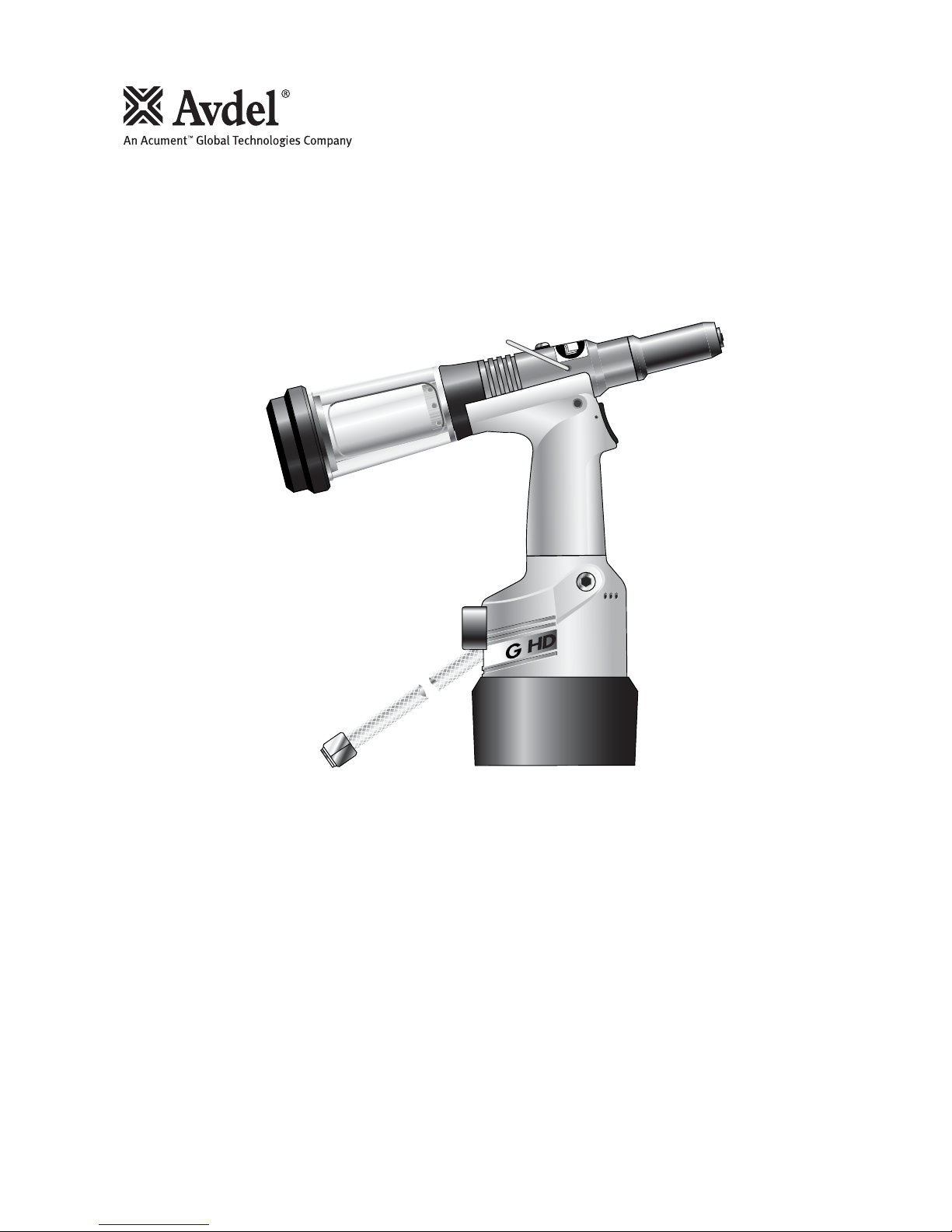
Hydro-Pneumatic Power Tool
Genesis®G2HD
Instruction Manual


3
Avdel UK Limited policy is one of continuous product development and improvement and we reserve the right to change the specification of any product without prior notice.
Warranty
Avdel installation tools carry a 12 month warranty against defects caused by faulty
materials or workmanship, the warranty period commencing from the date of delivery
confirmed by invoice or delivery note.
The warranty applies to the user/purchaser when sold through an authorised outlet, and
only when used for the intended purpose. The warranty is invalidated if the installation
tool is not serviced, maintained and operated according to the instructions contained in
the Instruction and Service Manuals.
In the event of a defect or failure, and at its sole discretion, Avdel undertakes only to
repair or replace faulty components.
Contents
Safety Rules 4
Specifications
Tool Specifications 5
Tool Dimensions 5
Intent of Use
Range of Fasteners 6
Part Numbering 6
Putting into Service
Air Supply 7
Operating Procedure 7
Adjusting the Vacuum Extraction 7
Nose Assemblies
Fitting and Servicing Instructions 8
Selection of Nose Tips 9&10
Accessories
Stem Deflector 11
Extension 11
Side Ejector 11
Swivel Heads 12
Preparing the Base Tool 13
Swivel Head Fitting Instructions 14
Swivel Head Servicing Instructions 15
Servicing the Tool
Daily / Weekly 16
Moly Lithium Grease EP 3753 Safety Data 16
MolyKote 55m & MolyKote 111 Safety Data 17
Service Kit 18
Annually 19
Head Assembly 19
Pneumatic Piston Assembly 20
Valve Spool Assembly 20
Trigger 20
General Assembly of Base Tool
General Assembly and Parts List 22-23
Priming
Oil Details 24
Hyspin VG 32 Oil Safety Data 24
Priming Kit 24
Priming Procedure 25
Fault Diagnosis
Symptom, Possible Cause & Remedy 26

4
Safety Rules
1Do not use outside the design intent.
2Do not use equipment with this tool/machine other than that recommended and supplied by Avdel UK Limited.
3Any modification undertaken by the customer to the tool/machine, nose assemblies, accessories or any equipment supplied by Avdel UK
Limited or their representatives, shall be the customer’s entire responsibility. Avdel UK Limited will be pleased to advise upon any
proposed modification.
4The tool/machine must be maintained in a safe working condition at all times and examined at regular intervals for damage and function
by trained competent personnel. Any dismantling procedure shall be undertaken only by personnel trained in Avdel UK Limited procedures.
Do not dismantle this tool/machine without prior reference to the maintenance instructions. Please contact Avdel UK Limited with your
training requirements.
5The tool/machine shall at all times be operated in accordance with relevant Health and Safety legislation. In the U.K. the “Health and
Safety at Work etc. Act 1974” applies. Any question regarding the correct operation of the tool/machine and operator safety should be
directed to Avdel UK Limited.
6The precautions to be observed when using this tool/machine must be explained by the customer to all operators.
7Always disconnect the airline from the tool/machine inlet before attempting to adjust, fit or remove a nose assembly.
8Do not operate a tool/machine that is directed towards any person(s) or the operator.
9Always adopt a firm footing or a stable position before operating the tool/machine.
10 Ensure that vent holes do not become blocked or covered.
11 The operating pressure shall not exceed 7 bar.
12 Do not operate the tool if it is not fitted with a complete nose assembly or swivel head unless specifically instructed otherwise.
13 Care shall be taken to ensure that spent stems are not allowed to create a hazard.
14 If the tool is fitted with a stem collector,it must be emptied when half full.
15 If the G2 tool is fitted with a stem deflector, it should be rotated until the aperture is facing way from the operator and other person(s)
working in the vicinity.
16 When using the tool, the wearing of safety glasses is required both by the operator and others in the vicinity to protect against fastener
ejection, should a fastener be placed ‘in air’. We recommend wearing gloves if there are sharp edges or corners on the application.
17 Take care to avoid entanglement of loose clothes, ties, long hair, cleaning rags etc. in the moving parts of the tool which should be kept
dry and clean for best possible grip.
18 When carrying the tool from place to place keep hands away from the trigger/lever to avoid inadvertent start up.
19 Excessive contact with hydraulic fluid oil should be avoided. To minimize the possibility of rashes, care should be taken to wash
thoroughly.
This instruction manual must be read with particular attention to the following safety rules, by any person
installing, operating, or servicing this tool.
Tool Specification
Specifications
5
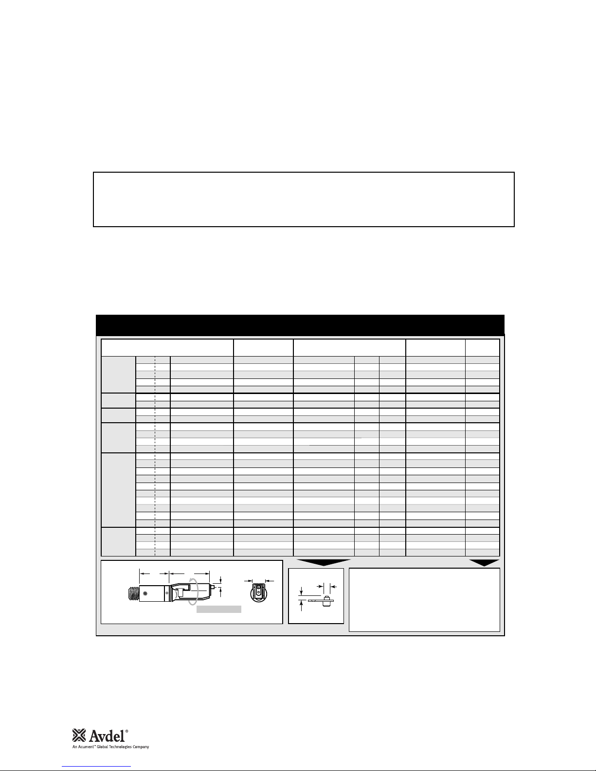
Air Pressure Minimum - Maximum 5-7 bar
Free Air Volume Required @ 5.5 bar 2.1 litres
Stroke Minimum 17 mm
Pull Force @ 5.5 bar 9.34 kN
Cycle Time Approximately 0.9 seconds
Noise Level 75 dB(A)
Weight Without nose equipment 1.35 kg
Vibration Less than 2.5 m/s2
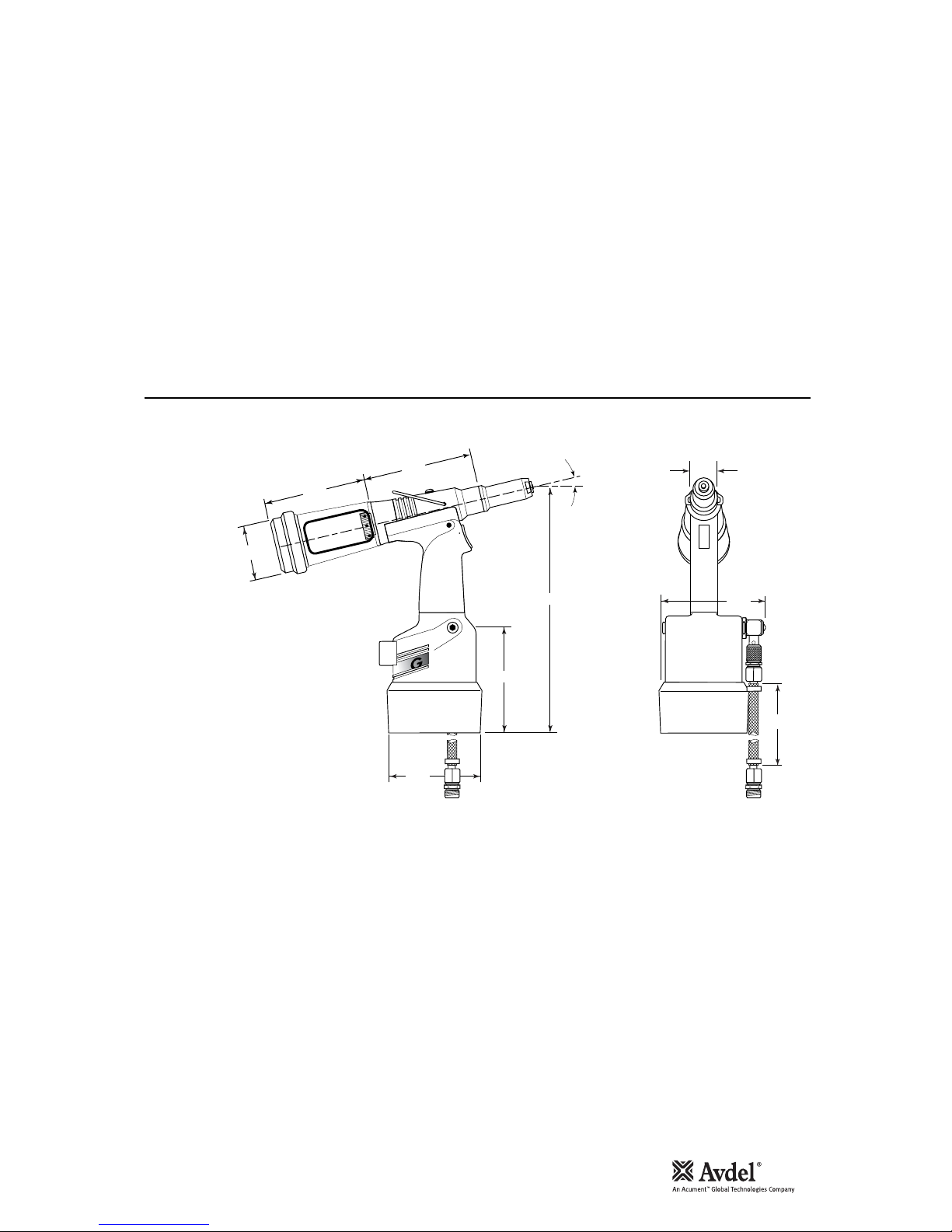
30
121
150
110
120
284
2
12∞30'
126
116
70
Dimensions in millimetres
Tool Dimensions
MODEL 71211
6
Intent of Use
G2HD is a hydro-pneumatic tool designed to place Avdel®
breakstem fasteners at high speed making it ideal for batch or
flow-line assembly in a wide variety of applications throughout all
industries. It can place all fasteners listed opposite.
The tool features an adjustable vacuum system for fastener
retention and trouble free collection of the spent stems
regardless of tool orientation. See the ‘Operating Procedure’ on
page 7 for adjustment instructions.
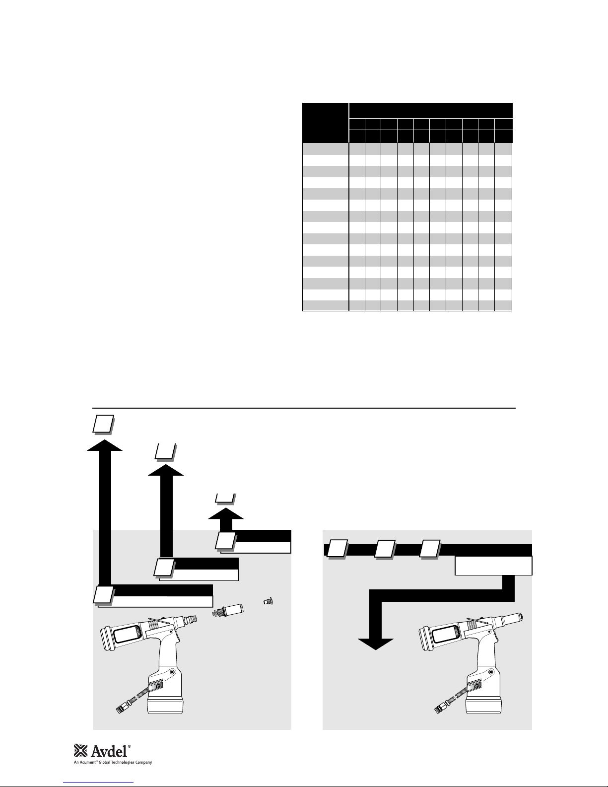
A complete tool, except the 71211-00039, is made up of three
separate elements which will be supplied individually. See
diagram below.
If you wish to place most of the fasteners in the table opposite,
you can order the 71211-00039 complete tool comprising of:
• 71211 base tool
• 71210-15000 nose assembly
• Nose tips 71210-05002, 71210-16070 and 07381-04701,
two screwed into the base cover. Fit nose tip as indicated
page 9 or 11.
You can order the above three nose tips and nose
assembly as a nose assembly kit part number 71210-
15100.
• For some fasteners the base tool and nose assembly
and nose tip must be ordered separately.
NOSE EQUIPMENT MUST BE FITTED AS DESCRIBED ON
PAGE 9.
FASTENER
NAME
MM
IN
FASTENER SIZE ( )
AVEX®
STAVEX®
AVINOX®
AVIBULB®
ETR
BULBEX®
T-LOK®
AVDEL®SR
MONOBOLT®
INTERLOCK®
TLR®
AVDEL®
MBC
MBC/LC
AVSEAL®
3 3.2 4.0 4.3 4.8 5 5.2 6 6.5 7
–1/85/32 –3/16 –––––
●●
●
●
●
●
●
●
●
●
●
●
●
●
●
●
●
●
●
●
●
●
●
●
●
●
●
●
●
●
●
●
●
●
●●●●
COMPLETE TOOL
71211-00 . . . *
BASE TOOL
1
1
2
3
1
NOSE ASSEMBLY
NOSE TIP
2
71211-02000
71210-15000
see note 3
2
3++=
3
2
2
The part number of the base tool remains the same whichever nose assembly, or nose tip is fitted. See the General
Assembly pages 22-23. If a swivel head is fitted, the same base tool must be adapted. See details page 13.
The nose tip part number relates to a specific fastener. If access to the application is
restricted, some extended nose tips are available. See page 10 for selection table.
This single nose assembly will allow placing of non-aerospace fasteners by simply selecting the
appropriate nose tip from the range of type 1 nose tips. Other nose assemblies are available for
applications with restricted access, for aerospace and special fasteners. See tables pages 8 & 10. A
nose assembly can be substituted by a swivel head (see pages 12-15). In this case the nose tip is part of
the swivel head.
* ADD 3 DIGITS FROM THE
LAST COLUMN OF A NOSE
TIP TABLE ON PAGE 8 OR 10.
FOR TOOLS WITH SWIVEL
HEADS USE TABLE PAGES 12-
13.
Range of Fasteners
Part Numbering
7
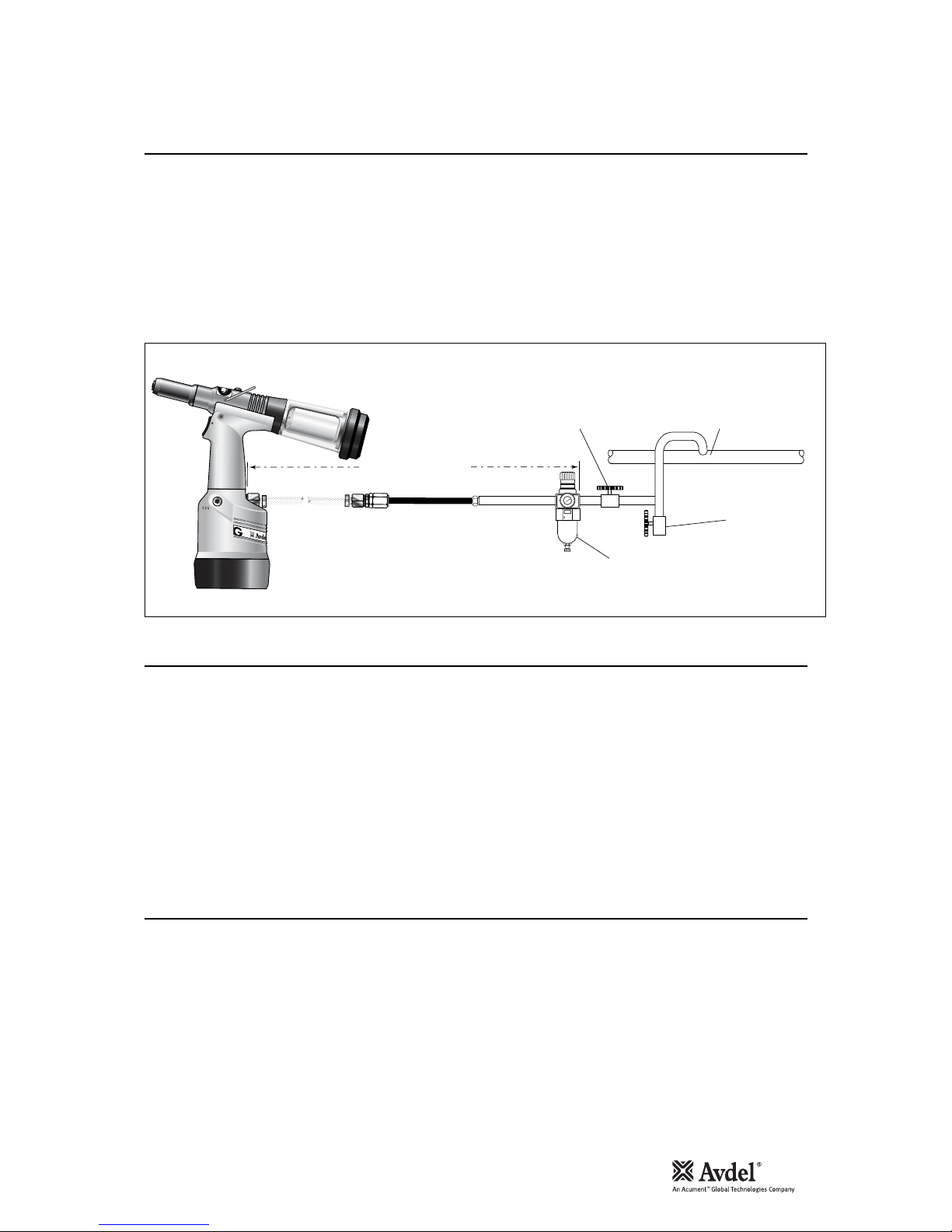
All tools are operated with compressed air at an optimum pressure of 5.5 bar. We recommend the use of pressure regulators and filtering
systems on the main air supply. These should be fitted within 3 metres of the tool (see diagram below) to ensure maximum tool life and
minimum tool maintenance.
Air supply hoses should have a minimum working effective pressure rating of 150% of the maximum pressure produced in the system or
10 bar, whichever is the highest. Air hoses should be oil resistant, have an abrasion resistant exterior and should be armoured where
operating conditions may result in hoses being damaged. All air hoses MUST have a minimum bore diameter of 6.4 millimetres or 1/4inch.
Read servicing daily details page 16.
8
6
4
2
0
10
12
14
16
TAKE OFF POINT
FROM
MAIN SUPPLY
STOP COCK
(USED DURING MAINTENANCE
OF FILTER/REGULATOR UNIT)
MAIN SUPPLY
DRAIN POINT
PRESSURE REGULATOR
AND FILTER (DRAIN DAILY)
3 METRES MAXIMUM
2
•Ensure that either the correct nose assembly or swivel head suitable for the fastener is fitted (see pages 8-10 and 12-15).
•Connect the tool to the air supply.
•Insert the fastener stem into the nose of the tool. If using a nose assembly, the fastener should remain held in by the vacuum system.
If not, adjust the vacuum extraction rotary valve 60.
•If using a swivel head, the vacuum extraction is disabled but the jaws themselves will grip the fastener.
•Bring the tool with the fastener to the application so that the protruding fastener enters squarely the hole of the application.
•Fully actuate the trigger. The tool cycle will broach the fastener and with standard nose assemblies the broken stem will be projected
to the rear of the tool .
•Using a screwdriver, turn rotary valve 60 until the air flow at the rear of the tool ceases.
•With the nose of the tool pointing downwards, insert a fastener into the nose and hold it into position.
•Turn the rotary valve either way until there is sufficient suction to retain the fastener.
Item numbers in bold refer to the general assembly drawing and parts list on pages 22-23.
Putting into Service
Air Supply
Operating Procedure
Adjusting Vacuum Extraction

8
Nose assemblies should be serviced at weekly intervals. You should hold some stock of all internal components of the nose
assembly and nose tips as they will need regular replacement.
•Remove the nose equipment using the reverse procedure to the ‘Fitting instructions’.
•Any worn or damaged part should be replaced.
•Clean and check wear on jaws.
•Ensure that the jaw spreader is not distorted.
•Check spring 7is not distorted.
•Assemble according to fitting instructions above.
* Item included in the G2 service kit. For complete list see page 18.
IMPORTANT
The air supply must be disconnected when fitting or removing nose assemblies.
Item numbers in bold refer to nose assembly components in all 3 nose tip tables.
•Lightly coat jaws 4with Moly lithium grease*.
•Drop jaws 4into jaw housing 3.
•Insert jaw spreader 5into jaw housing 3.
•Locate buffer 6on jaw spreader 5.
•Locate spring 7onto jaw spreader 5.
•Fit locking ring 8onto the jaw spreader housing of the tool.
•Holding tool pointing down, screw the assembled jaw housing onto the jaw spreader housing and tighten with spanner.
•Screw the nose tip into nose casing 1and tighten with spanner*.
•Place nose casing 1over jaw housing 3and screw onto the tool, tightening with spanner*.
Fitting Instructions
Servicing Instructions

Nose Tips
9
IMPORTANT
Nose assemblies do NOT include nose tips. Nose tips must be ordered separately.
A tool (except part number 71211-00039) must always be fitted with the correct nose assembly and nose tip for your fastener but if you wish to
order a nose assembly or a nose tip separately, refer to the ‘NOSE TIPS’ tables below and page 10.
If your application presents no access restriction use a type ‘1’ nose tip unless you are placing aerospace fasteners which requires a type ‘3’ nose
tip.
Dimensions ‘A’ and ‘B’ below will help you assess the suitability of a particular nose tip.
You should also check that the dimensions of the nose casing will not restrict access to your application. If access is restricted type ‘2’ nose tips are
available for some fasteners. Refer to the table page 10.
It is essential that nose assembly and nose tip are compatible with the fastener prior to operating the tool. If you have ordered a 71211-00039
complete tool, it is important that you check that the nose tip already fitted to the nose assembly is the correct one to place your fastener by sliding
the fastener stem into the nose tip. No force should be required and play should be minimal. The two alternative nose tips are screwed into the
base of the tool.
Swivel heads are available as an alternative to nose assemblies when further reach is required. See page 12-15 in the ‘Accessories’ section.
1
In inches then in millimetres.
2
Head forming nose tips for use with countersunk heads
ONLY.
3
Long nose tip for deep placing.
4
Dome head.
5
Countersunk.
TYPE 1
NOSE TIPS
NOSE ASSEMBLY
part nº 71210-15000
(+ 3 nose tips above = 71210-15100)
FASTENER
MATERIAL
Ø1
NOSE TIP (mm) see
below
PART Nº 'A' 'B'NAME
Al Alloy
Steel
Al Alloy
Al Alloy
Al Alloy
Steel
Al Alloy
Al Alloy
Al Alloy
Steel
Al Alloy
Any
Al Alloy
Al Alloy
Al Alloy
Al Alloy
Al Alloy
Al Alloy
Al Alloy
Al Alloy
Al Alloy
Al Alloy
Al Alloy
Al Alloy
Al Alloy
Stainless Steel
Stainless Steel
Stainless Steel
Steel
Steel
Steel
Steel
Steel
Any
Any
Any
Any
Any
Steel
Steel
Steel
Steel
Steel
Stainless Steel
Stainless Steel
Stainless Steel
Any
Any
Any
1/8
1/8
1/8
–
5/32
5/32
5/32
3/16
3/16
3/16
3/16
3/16
5/32
3/16
–
–
–
–
–
–
–
–
–
–
3/16
1/8
5/32
3/16
–
3/16
1/8
5/32
3/16
1/8
5/32
3/16
3/16
3/16
1/8
5/32
3/16
3/16
3/16
1/8
5/32
3/16
1/8
5/32
3/16
6.35
3.3
2.9
6.35
3.3
2.8
3.3
2.8
3.3
3.3
4.1
4.1
3.3
2.8
4.9
6.9
4.7
6.9
5.3
7.2
5.4
7.3
5.4
7.3
4.1
3.3
2.8
4.8
3.3
3.3
3.3
2.8
4.8
6.35
3.3
5.7
5.7
2.8
3.3
2.8
2.8
3.3
2.8
3.3
2.8
2.8
6.35
3.3
3.3
12.7
12.7
12.7
12.7
12.7
12.7
12.7
12.7
19.0
12.7
12.7
12.7
12.7
12.7
12.7
12.7
12.7
12.7
12.7
12.7
12.7
12.7
12.7
12.7
12.7
12.7
12.7
12.7
12.7
12.7
12.7
12.7
12.7
12.7
12.7
12.7
12.7
12.7
12.7
12.7
12.7
19.0
12.7
12.7
12.7
12.7
12.7
12.7
12.7
71210-05002
71210-16070
07340-064012
71210-05002
71210-16070
07381-04701
07340-065012
07381-04701
07340-04800
07490-04401
07340-066012
71210-16020
71210-16070
07381-04701
71210-16001
71210-160063
71210-16002
71210-160073
71210-16003
71210-160083
71210-16004
71210-160093
71210-16005
71210-160103
07605-00220
71210-16070
07381-04701
07498-01401
07340-06201
07340-06201
71210-16070
07381-04701
07498-01401
71210-05002
71210-16070
07348-070014
71210-160505
07381-04701
71210-16070
07381-04701
07381-04701
07340-04800
07381-04701
71210-16070
07381-04701
07381-04701
71210-05002
07340-06201
07340-06201
3.2
3.2
3.2
3
4.0
4.0
4.0
4.8
4.8
4.8
4.8
4.8
4.0
4.8
4
4
5
5
6
6
6.5
6.5
7
7
4.8
3.2
4.0
4.8
4.3
4.8
3.2
4.0
4.8
3.2
4.0
4.8
1.8
4.8
3.2
4.0
4.8
4.8
4.8
3.2
4.0
4.8
3.2
4.0
4.8
AVEX®
Large flange
MONOBOLT®
BULBEX®
AVSEAL®
TLR®
AVINOX®II
T-LOK®
AVIBULB®
AVDEL®SR
INTERLOCK®
STAVEX®
Large flange
Countersunk
Q™RIVET
…039*
…039*
…003
…039
…039*
…039*
…009
…039
…016
…017
…015
…200
…039*
…039*
…160
…180
…161
…181
…162
…182
…163
…183
…164
…184
…140
…039*
…039*
…082
…120
…120
…039*
…039*
…082
…039*
…039*
…062
…064
…039
…039
…039
…039
…016
…039
…039
…039
…039
…039
…120
…120
A
B
ITEM DESCRIPTION PART Nº
1 NOSE CASING 07340-00306
2 'O' RING 07003-00067
3 JAW HOUSING 07340-00304
4 JAWS 71210-15001
5 JAW SPREADER 07498-04502
6 BUFFER 71210-05001
7 SPRING 07500-00418
8 LOCKING RING 07340-00327
*
Complete tool part number 71211-00039 does
not only include the 71210-15000 nose assembly
below but also the following three nose tips:
71210-05002, 71210-16070 and 07381-04701
making up a nose assembly kit part number 71210-
15100.
Use the nose tip listed in the table.
COMPLETE TOOL
PART NUMBER :
precede with 71211-00
* See top left
8 7 6 5 4 23 1 61
22.9

10
1
In inches then in millimetres.
ITEM DESCRIPTION PART Nº
1 NOSE CASING 07340-02804
2 'O' RING 07003-00067
3 JAW HOUSING 07340-00304
4 JAWS 71210-15001
5 JAW SPREADER 07498-04502
6 BUFFER 71210-05001
7 SPRING 07500-00418
8 LOCKING RING 07340-00327
COMPLETE TOOL
PART NUMBER :
precede with
71211-00
NOSE ASSEMBLY
part nº 71210-15200
A
B
TYPE 2 NOSE TIPS ARE EXTENDED
TO ALLOW ACCESS INTO
APPLICATIONS WHERE TYPE 1
NOSE TIPS WILL NOT REACH.
TYPE 2
NOSE TIPS
8 7 6 5 423158.3
22.9
FASTENER
MATERIAL
Ø1
NOSE TIP (mm) see
below
PART Nº 'A' 'B'NAME
Aluminium Alloy
Steel
Aluminium Alloy
Steel
Aluminium Alloy
Steel
Aluminium Alloy
Aluminium Alloy
Steel
Steel
Steel
Steel
Steel
Stainless Steel
Stainless Steel
Stainless Steel
Steel
Steel
Steel/Brass
1/8
1/8
5/32
5/32
3/16
3/16
5/32
3/16
–
3/16
1/8
5/32
3/16
1/8
5/32
3/16
1/8
5/32
–
12.95
11.4
11.4
10.0
10.0
11.8
11.4
10.0
10.0
10.0
11.4
10.0
10.0
11.4
10.0
10.0
11.4
10.0
10.0
9.5
9.5
9.5
12.7
12.7
12.7
9.5
12.7
12.7
12.7
9.5
12.7
12.7
9.5
12.7
12.7
9.5
12.7
12.7
07340-02805
07340-02806
07340-02806
07340-02807
07340-02807
07340-07301
07340-02806
07340-02807
07241-07101
07241-07101
07340-02806
07340-02807
07340-02807
07340-02806
07340-02807
07340-02807
07340-02806
07340-02807
07340-02807
3.2
3.2
4.0
4.0
4.8
4.8
4.0
4.8
4.3
4.8
3.2
4.0
4.8
3.2
4.0
4.8
3.2
4.0
5.2
AVEX®
BULBEX®
T-LOK®
STAVEX®
AVIBULB®
E.T.R
…002
…008
…008
…014
…014
…018
…008
…014
…121
…121
…008
…014
…014
…008
…014
…014
…008
…014
…014
TYPE 3
NOSE TIPS
COMPLETE TOOL
PART NUMBER :
precede with
71211-00
156.3
22.9
1
In inches then in millimetres.
O
Oversize
NOSE ASSEMBLY
part nº 71210-15300
ITEM DESCRIPTION PART Nº
1 NOSE CASING 07344-02001
2 'O' RING 07003-00067
3 JAW HOUSING 07340-00304
4 JAWS 71210-15001
5 JAW SPREADER 07498-04502
6 BUFFER 71210-05001
7 SPRING 07500-00418
8 LOCKING RING 07340-00327
TYPE 3 NOSE TIPS ARE SPECIFICALLY FOR THE AEROSPACE
FASTENERS LISTED BELOW.
FASTENER
MATERIAL
Ø1
NOSE TIP (mm) see
below
PART Nº 'A' 'B'NAME
Al Alloy
Al Alloy
O
Stainless Steel
Al Alloy
Al Alloy
O
Stainless Steel
Al Alloy
Al Alloy
O
Any
Any
Al Alloy
Any
Any
Al Alloy
1/8
1/8
1/8
5/32
5/32
5/32
3/16
3/16
1/8
5/32
3/16
1/8
5/32
3/16
2.5
2.5
3.3
2.5
2.5
3.3
2.5
2.5
4.8
5.0
5.1
4.6
4.6
4.6
12.7
12.7
12.7
12.7
12.7
12.7
12.7
12.7
12.7
12.7
12.7
12.7
12.7
12.7
71210-16030
71210-16031
71210-16032
71210-16033
71210-16034
71210-16035
71210-16036
71210-16037
07340-06701
07340-06801
07340-06901
07344-04701
07344-04701
07344-04701
3.2
3.2
3.2
4.0
4.0
4.0
4.8
4.8
3.2
4.0
4.8
3.2
4.0
4.8
AVDEL®
MBC
MBC L/C
…283
…284
…285
…288
…289
…290
…293
…294
…300
…305
…310
…320
…320
…320
A
B
8 7 6 5 423
Nose Tips

11
ADAPTOR NUT
71210-20101
STEM DEFLECTOR
07340-00342
The stem deflector is a very simple alternative to the standard stem
collector and allows access in restricted areas. To replace the stem
collector with the stem deflector proceed as follows:
•Unscrew retaining nut 21 by inserting a 3 millimetre diameter rod
into one of the holes.
•Remove retaining nut 21 and the stem collector assembly, items
15, 16, 17, 18, 19, and 20.
•Screw the adaptor nut onto end cap 22.
•Push the boss end of the stem deflector into the internal groove
of the adaptor nut.
•Rotate the stem deflector until the aperture faces away from the
operator and other person(s) in the vicinity.
Item numbers in bold refer to the general assembly drawing and parts list on pages 22-23.
INNER
71210-20301
OUTER
71210-20302
STEM DEFLECTOR: 71210-20100
EXTENSION PART NUMBER: 71210-20300
INNER
EXTENSION
OUTER CASING
8-32 x 1/4" SOCKET
CAP HEAD SCREW
Part number: 07498-00900
for fasteners with a stem larger than 3.1 mm (1/8") Ø
Fitted between the tool and the nose assembly the extension allows
access into deep channels.
•To fit the extension, remove any nose assembly components.
•Screw the inner extension to jaw spreader housing 1.
•Screw the outer onto head assembly 4.
•Fit the nose assembly onto the extension.
Fitted between the tool and the nose assembly, the side ejector
forces fastener stems to eject at the front of the tool and reaches
into deep channels.
It cannot be used in conjunction to a swivel head. Select the correct
part number (below right) according to the stem diameter of the
fastener.
For greater ease of use, it is recommended that the stem collector
or deflector is replaced with safety cap part number 71210-20201
as used with swivel heads. See page 14 for fitting instructions, but
note that the stop nut is not fitted in this case.
•To fit the side ejector, remove any nose assembly components.
•Remove the socket cap screw from the side ejector.
•Screw the inner extension onto jaw spreader housing 1.
•Screw the outer casing onto head assembly 4.
•Replace the socket cap screw securing with Loctite Screwlock
222, part number 07900-00371.
•Screw the nose assembly onto the side ejector.
Stem Deflector
Accessories
Extension
Side Ejector
Swivel Heads
Accessories
12
Instead of a nose assembly, a swivel head can be fitted to a base tool. It allows 360° rotation of the tool about the nose tip and allows
access into many applications otherwise too restrictive. There are two types of swivel heads: the straight swivel head with the nose tip
slightly offset from the centre line of the tool head and the right-angle swivel head with the nose tip on a perpendicular axis to the head of
the tool. See drawings below for dimensions and pages 14-15 for detail.
IMPORTANT
PRIOR to fitting a swivel head, the base tool must be adapted. See Preparing the base tool opposite.
In contrast to nose assemblies part numbers of swivel heads do INCLUDE a nose tip as shown below.
Swivel heads are supplied separately for fitting to a base tool forming a complete tool. See table below for part numbers. Jaws and nose
tips vary depending on the fastener to be placed but all other components remain the same within each type of swivel head. See the
‘capability’ tables below and ‘constant component table’ page 15.
'A’ and ‘B’ dimensions will help you assess the accessibility of your application.
1
In inches then in millimetres.
2
Long nose tip for deep placing.
O
Oversize
FASTENER
MATERIAL
Ø1
NOSE TIP (mm)SWIVEL HEAD
PART Nº
JAWS see
below
'A' 'B'NAME
Al Alloy
Steel
Al Alloy
Steel
Al Alloy
Al Alloy
Al Alloy
Stainless Steel
Stainless Steel
Al Alloy
Al Alloy
Al Alloy
Al Alloy
Al Alloy
Al Alloy
O
Stainless Steel
Al Alloy
Al Alloy
O
Al Alloy
Al Alloy
O
Al Alloy
Al Alloy
Al Alloy
Al Alloy
Al Alloy
Al Alloy
O
Al Alloy
1/8
1/8
5/32
5/32
3/16
5/32
3/16
1/8
5/32
–
–
–
–
1/8
1/8
1/8
5/32
5/32
3/16
3/16
1/8
5/32
3/16
1/8
5/32
5/32
3/16
3.81
3.81
3.81
3.81
3.81
3.81
3.81
3.81
3.81
1.95
4.11
2.00
4.11
1.17
1.17
3.81
0.84
0.84
0.25
0.25
1.9
2.36
2.46
2.03
2.03
2.03
2.03
7.87
7.87
7.87
7.87
7.87
7.87
7.87
7.87
7.87
6.35
6.35
7.62
7.62
5.08
5.08
5.08
6.6
6.6
8.13
8.13
4.75
6.35
7.92
7.87
7.87
7.87
7.87
07345-03000
07345-03100
07345-03100
07345-03200
07345-03200
07345-03100
07345-03200
07345-03100
07345-03200
07494-06000
07494-06600
07494-06100
07494-06700
07345-03300
07494-03600
07494-03000
07345-03400
07494-03700
07345-03500
07494-03800
07345-04000
07345-04100
07345-04200
07345-04700
07345-04700
07345-04800
07345-04800
PART Nº
07340-00213
07340-00213
07340-00213
07490-04602
07490-04602
07340-00213
07490-04602
07340-00213
07490-04602
07340-00213
07340-00213
07340-00213
07340-00213
07340-00229
07340-00229
07340-00213
07340-00229
07340-00229
07498-04401
07498-04401
07340-00229
07340-00229
07498-04401
07340-00229
07340-00229
07498-04401
07498-04401
PART Nº
07345-03600
07345-03700
07345-03700
07345-03800
07345-03800
07345-03700
07345-03800
07345-03700
07345-03800
07494-06001
07494-066012
07494-06101
07494-067012
07345-03301
07494-03601
07494-03011
07345-03401
07494-03701
07345-03501
07494-03801
07165-00701
07165-00702
07165-00703
07345-04701
07345-04701
07345-04701
07345-04701
3.2
3.2
4.0
4.0
4.8
4.0
4.8
3.2
4.0
4
4
5
5
3.2
3.2
3.2
4.0
4.0
4.8
4.8
3.2
4.0
4.8
3.2
4.0
4.0
4.8
AVEX®
BULBEX®
AVINOX®
AVSEAL®
AVDEL®
MBC
MBC L/C
…001
…004
…004
…010
…010
…004
…010
…004
…010
…160
…180
…161
…181
…283
…284
…285
…288
…289
…293
…294
…300
…305
…310
…320
…320
…327
…327
COMPLETE TOOL PART NUMBER :
precede with 71211-30
(the stop nut and safety cap are included)
IMPORTANT: by opposition to complete tools
with nose assemblies, those fitted with swivel heads
include the nose tip as a part of the head.
STRAIGHT SWIVEL HEAD capability
A
B
360°rotation
56 92
6
20

1
In inches then in millimetres.
2
Long nose tip for deep placing.
O
Oversize
FASTENER
MATERIAL
Ø1
NOSE TIP (mm)SWIVEL HEAD
PART Nº
JAWS see
below
'A' 'B'NAME
Al Alloy
Steel
Al Alloy
Steel
Al Alloy
Al Alloy
Al Alloy
Stainless Steel
Stainless Steel
Al Alloy
Al Alloy
Al Alloy
Al Alloy
Al Alloy
Al Alloy
O
Stainless Steel
Al Alloy
Al Alloy
O
Al Alloy
Al Alloy
O
Al Alloy
Al Alloy
Al Alloy
Al Alloy
Al Alloy
Al Alloy
O
Al Alloy
1/8
1/8
5/32
5/32
3/16
5/32
3/16
1/8
5/32
–
–
–
–
1/8
1/8
1/8
5/32
5/32
3/16
3/16
1/8
5/32
3/16
1/8
5/32
5/32
3/16
3.81
3.81
3.81
3.81
3.81
3.81
3.81
3.81
3.81
1.95
4.11
2.00
4.11
1.17
1.17
3.81
0.84
0.84
0.25
0.25
1.9
2.36
2.46
2.03
2.03
2.03
2.03
7.87
7.87
7.87
7.87
7.87
7.87
7.87
7.87
7.87
6.35
6.35
7.62
7.62
5.08
5.08
5.08
6.6
6.6
8.13
8.13
4.75
6.35
7.92
7.87
7.87
7.87
7.87
07346-03000
07346-03100
07346-03100
07346-03200
07346-03200
07346-03100
07346-03200
07346-03100
07346-03200
07495-04000
07495-04700
07495-04100
07495-04800
07346-03300
07495-03600
07495-03000
07346-03400
07495-03700
07346-03500
07495-03800
07346-04000
07346-04100
07346-04200
07346-04500
07346-04500
07346-04600
07346-04600
PART Nº
07340-00213
07340-00213
07340-00213
07490-04602
07490-04602
07340-00213
07490-04602
07340-00213
07490-04602
07340-00213
07340-00213
07340-00213
07340-00213
07340-00229
07340-00229
07340-00213
07340-00229
07340-00229
07498-04401
07498-04401
07340-00229
07340-00229
07498-04401
07340-00229
07340-00229
07498-04401
07498-04401
PART Nº
07345-03600
07345-03700
07345-03700
07345-03800
07345-03800
07345-03700
07345-03800
07345-03700
07345-03800
07494-06001
07494-066012
07494-06101
07494-067012
07345-03301
07494-03601
07494-03011
07345-03401
07494-03701
07345-03501
07494-03801
07165-00701
07165-00702
07165-00703
07345-04701
07345-04701
07345-04701
07345-04701
3.2
3.2
4.0
4.0
4.8
4.0
4.8
3.2
4.0
4
4
5
5
3.2
3.2
3.2
4.0
4.0
4.8
4.8
3.2
4.0
4.8
3.2
4.0
4.0
4.8
AVEX®
BULBEX®
AVINOX®
AVSEAL®
AVDEL®
MBC
MBC L/C
…001
…004
…004
…010
…010
…004
…010
…004
…010
…160
…180
…161
…181
…283
…284
…285
…288
…289
…293
…294
…300
…305
…310
…320
…320
…327
…327
COMPLETE TOOL PART NUMBER :
precede with 71211-40
(the stop nut and safety cap are included)
IMPORTANT: by opposition to complete tools
with nose assemblies, those fitted with swivel heads
include the nose tip as a part of the head.
RIGHT-ANGLE SWIVEL HEAD capability
7.6
32
20
52
56
74
97
A
B
360°rotation
12
7
23
1745 18 19
64
21 20
63
22
6
3
5
67
68
71210-20202
STOP NUT
71210-20201
SAFETY CAP
•Disconnect the air supply.
•Remove any nose assembly items.
•Remove retaining nut 22 and all elements
of the stem collector (items 18, 19, 20,
21, 45, 63, 64). Note that ‘O’ ring 17
remains.
•Replace the above with a safety cap as
shown in drawing opposite.
•Unscrew jaw spreader housing 1and
remove with ‘O’ ring 2, locknut 3, ‘O’ rings
68 and 67, and seal housing 5.
•Screw stop nut 71210-20202 onto the
front of head piston 7as far as it will go by
hand.
•Re-fit jaw spreader housing 1and ‘O’ ring
2.
•Unscrew the stop nut until it locks against
jaw spreader housing 1and tighten with
spanner.
The tool is now ready to be fitted with a swivel
head. Instructions are on page 14.
Base tool to receive a nose assembly
Base tool to receive a swivel head
Preparing the Base Tool
Accessories
13
14
Accessories
The fitting and servicing procedures for both types of head are almost identical. Differences are clearly indicated.
IMPORTANT
PRIOR to fitting a swivel head, the base tool must be adapted. See Preparing the base tool opposite.
The air supply must be disconnected when fitting or removing swivel heads.
16
1
3
12
14
13
16
6
5
21
22 11
7
9
8
8
8
10
17 18
19 20
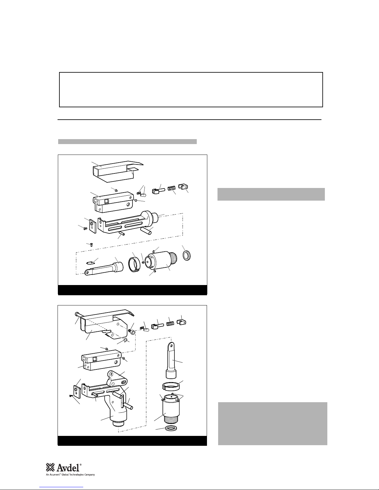
STRAIGHT SWIVEL HEAD
2
1
15
9
8
8
10
7
11
17
23 18 19 20
316
16
4
12
14
13
6
6
5
RIGHT-ANGLE HEAD
AFit locking ring 10 over jaw spreader housing 1.
BCoat screw 13 with thread locking adhesive and use to
secure nose tip 14 onto body 5.
CLightly lubricate items 17, 18, 19, 20 and insert into
jaw carrier 3 as shown. Secure with screws 16.
DPosition lever 4 into body 5 and hold in place with pin
15 through the hole of body 5 (not a slot).
ELubricate the sides of the jaw carrier assembly and
insert into body 5.
FLubricate rollers 8and ENSURE that they will freely
rotate in the holes of adaptor 9. If necessary ream the
holes.
GPosition spring clip 7over adaptor 9past the holes for
the rollers and rotate until the locating peg is aligned
with the corresponding hole in adaptor 9(smallest
hole).
HFit adaptor 9over the end of body 5and drop rollers 8
into place. Push spring clip 7over rollers 8.
IInsert spindle 11 through adaptor 9into jaw carrier 3
until the hole lines up with slot in body 5. Temporarily
hold in place with pin 6.
JInsert pin 12 through the front slot of body 5into jaw
carrier 3.
KHold the assembly vertical to prevent all pins dropping
and slide the jaw carrier assembly back and forth a few
times to ensure free movement. Go to M.
LRemove screws 23 (4 off) and guard 1. On a straight
swivel head also remove screw 21 and platform 22.
MPush pin(s) 6out and let spindle 11 drop out. Screw
spindle 11 onto the jaw spreader housing of the tool,
leaving the small screw fixing hole uppermost for
straight swivel. Tighten gently with a tommy bar.
NScrew the assembly over spindle 11 onto the tool
handle. Replace pin(s) 6.
OOn straight swivel heads attach platform 22 onto the
top of the spindle with screw 21. Deburr the back end
of platform 22 so that it cannot catch on guard 1.
PSnap guard 1over the assembly, align screw holes in
guard with tapped holes in body assembly.
QInsert pivot pin 15 through slots in guard and hole in
body. Fit circlip 2 onto pivot pin so that the circlip seats
in groove provided.
RCoat the thread of screws 23 (4 off) with thread locking
adhesive and screw into body assembly securing guard
to body assembly.
Swivel Head Fitting Instructions
The following procedure will allow you to assemble and fit either of the swivel heads to the tool. If you order a complete swivel head
rather than individual components, you will only need to start at stage L.
All moving parts should be lubricated. Unless stated otherwise use Moly lithium grease (details page 16).
When on grey tint, instructions refer only to the right-angle swivel head. Item numbers in bold refer to illustrations below.

Swivel Head Servicing Instructions
Accessories
15
5
7
17 18
19 20
Swivel heads should be serviced at weekly intervals.
•Remove the complete head using the reverse procedure to
the ‘Fitting instructions’ omitting step ‘L’.
•If guard 1is at all damaged it must be replaced by a new
one.
•Any worn or damaged parts should be replaced.
•Pay particular attention to jaw carrier items in the upper il-
lustration opposite as follows:
Check wear on jaws 17.
Check that jaw spreader tube 18 is not distorted.
Check that spring 19 is neither broken or distorted.
Check that spring guide 20 is not damaged.
•Check that spring clip 7is not distorted. When removing
spring clip 7, use two screwdrivers as shown in the lower
illustration opposite.
•Check for excessive wear on slots of body 5.
•Assemble according to fitting instructions.
While nose tips and jaws will vary for each swivel head, other components remain constant within each type of head. See table below.
For nose tips and jaws part numbers see pages 12-13.
CONSTANT COMPONENTS
ITEM STRAIGHT SWIVEL RIGHT-ANGLE SWIVEL
1
2
3
4
5
6
7
8
9
10
11
12
13
15
16
18
19
20
21
22
23
GUARD
CIRCLIP
JAW CARRIER
LEVER
BODY
PIVOT PIN
SPRING CLIP
ROLLER
ADAPTOR
LOCKING RING
SPINDLE
DOWEL PIN
SCREW
PIVOT PIN
SCREW
JAW SPREADER
SPRING
SPRING GUIDE
SCREW
PLATFORM
SCREW
07494-05000
-
07494-03026
-
07494-03015
07343-02207
07495-03900
07007-00039
07345-03001
07345-03003
07345-03002
07007-00038
07342-02207
-
07494-03028
07346-03101
07165-00305
07494-03027
07001-00368
07345-00401
-
07495-03003
07004-00105
07494-03026
07495-03004
07495-03002
07343-02207
07495-03900
07007-00039
07345-03001
07345-03003
07345-03002
07007-00038
07342-02207
07343-02207
07494-03028
07346-03101
07165-00305
07494-03027
–
–
07210-00804

16
Servicing the Tool
•Daily, before use or when first putting the tool into service, pour a few drops of clean, light lubricating oil into the air inlet of the tool
if no lubricator is fitted on air supply. If the tool is in continuous use, the air hose should be disconnected from the main air supply
and the tool lubricated every two to three hours.
•Check for air leaks. If damaged, hoses and couplings should be replaced.
•If there is no filter on the pressure regulator, bleed the air line to clear it of accumulated dirt or water before connecting the air hose
to the tool. If there is a filter, drain it.
•Check that the nose assembly or swivel head is correct for the fastener to be placed.
•Check the stroke of the tool meets the minimum specification (page 5). The last step of the Priming Procedure on page 25 explains
how to measure the stroke.
•Either a stem collector or a stem deflector must be fitted to the tool unless using a swivel head is fitted.
•Check that base cover 36 is fully tightened onto body 34.
•Ensure that rotary valve 60 is correctly adjusted for fastener retention (see ‘Operating Procedure’ page 7).
•Dismantle and clean the nose assembly with special attention to the jaws. Lubricate with Moly lithium grease before assembling.
•Check for oil leaks and air leaks in the air supply hose and fittings.
Grease can be ordered as a single item, the part number is shown in the service kit page 18.
First Aid
SKIN:
As the grease is completely water resistant it is best removed with an approved emulsifying skin cleaner.
INGESTION:
Ensure the individual drinks 30ml Milk of Magnesia, preferably in a cup of milk.
EYES:
Irritant but not harmful. Irrigate with water and seek medical attention.
Fire
FLASH POINT: Above 220°C.
Not classified as flammable.
Suitable extinguishing media: CO2, Halon or water spray if applied by an experienced operator.
Environment
Scrape up for burning or disposal on approved site.
Handling
Use barrier cream or oil resistant gloves
Storage
Away from heat and oxidising agent.
Item numbers in bold refer to the general assembly drawing and parts list on pages 22-23.
IMPORTANT
Read Safety Instructions on page 4.
The employer is responsible for ensuring that tool maintenance instructions are given to the appropriate personnel.
The operator should not be involved in maintenance or repair of the tool unless properly trained.
The tool shall be examined regularly for damage and malfunction.
Daily
Weekly
Moly Lithium Grease EP 3753 Safety Data

Molykote 55m Grease Safety Data
17
First Aid
SKIN:
Flush with water. Wipe off.
INGESTION:
No first aid should be needed.
EYES:
Flush with water.
Fire
FLASH POINT: Above 101.1°C. (closed cup)
Explosive Properties: No
Suitable Extinguishing Media: Carbon Dioxide Foam, Dry Powder or fine water spray.
Water can be used to cool fire exposed containers.
Environment
Do not allow large quantities to enter drains or surface waters.
Methods for cleaning up: Scrape up and place in suitable container fitted with a lid. The spilled product produces an extremely
slippery surface.
Harmful to aquatic organisms and may cause long-term adverse effects in the aquatic environment. However, due to the physical
form and water - insolubility of the product the bioavailability is negligible.
Handling
General ventilation is recommended. Avoid skin and eye contact.
Storage
Do not store with oxidizing agents. Keep container closed and store away from water or moisture.
First Aid
SKIN:
No first aid should be needed.
INGESTION:
No first aid should be needed.
EYES:
No first aid should be needed.
INHALATION:
No first aid should be needed.
Fire
FLASH POINT: Above 101.1°C. (closed cup)
Explosive Properties: No
Suitable Extinguishing Media: Carbon Dioxide Foam, Dry Powder or fine water spray.
Water can be used to cool fire exposed containers.
Environment
No adverse effects are predicted.
Handling
General ventilation is recommended. Avoid eye contact.
Storage
Do not store with oxidizing agents. Keep container closed and store away from water or moisture.
Molykote 111 Grease Safety Data
Servicing the Tool

Service kit
18
For an easy complete service, Avdel offers the complete service kit below.
PART Nº DESCRIPTIONPART Nº DESCRIPTION
SERVICE KIT : 71210-99990 Spanners are specified in inches and across flats unless otherwise stated
07900-00667 PISTON SLEEVE
07900-00692 TRIGGER VALVE EXTRACTOR
07900-00670 BULLET
07900-00672 'T' SPANNER
07900-00706 'T' SPANNER SPIGOT
07900-00684 GUIDE TUBE
07900-00685 INSERTION ROD
07900-00351 3 MM ALLEN KEY
07900-00469 2.5 MM ALLEN KEY
07900-00158 2 MM PIN PUNCH
07900-00164 CIRCLIP PLIERS
07900-00008 7/16 x 1/2SPANNER
07900-00012 9/16 x 5/8SPANNER
07900-00015 5/8x 11/16 SPANNER
07900-00686 PEG SPANNER
07900-00677 SEAL EXTRACTOR
07900-00698 STOP NUT
07900-00700 PRIMING PUMP
07992-00020 GREASE - MOLY LITHIUM E.P.3753
07992-00075 GREASE - MOLYKOTE 55M
07900-00775 GREASE - MOLYKOTE 111
Servicing the Tool

19
Annually
Servicing the Tool
The airline must be disconnected before any servicing or dismantling is attempted unless specifically instructed otherwise.
It is recommended that any dismantling operation be carried out in clean conditions.
Before proceeding with dismantling, empty the oil from the tool following the first three steps of the ‘Priming Procedure’ on page 25.
Prior to dismantling the tool it is necessary to remove the nose equipment. For instructions see the nose assemblies section, pages 8-10 or if
a swivel head was fitted pages 12-15.
For a complete service of the tool, we advise that you proceed with dismantling of sub-assemblies in the order shown.
After any dismantling REMEMBER to prime the tool and to fit an appropriate nose assembly or swivel head.
(or every 500,000 cycles whichever is the soonest)
Annually or every 500,000 cycles the tool should be completely dismantled and new components should be used where worn, damaged
or recommended. All ‘O’ rings and seals should be renewed and lubricated with Molykote 55m grease for pneumatic sealing or Molykote
111 for hydraulic sealing.
IMPORTANT
Read Safety Instructions on page 4.
The employer is responsible for ensuring that tool maintenance instructions are given to the appropriate personnel.
The operator should not be involved in maintenance or repair of the tool unless properly trained.
The tool shall be examined regularly for damage and malfunction.
•Unscrew retaining nut 22 and pull off stem collector assembly, items 18, 19, 20, 21, 45, 63, 64 and ‘O’ ring 17.
•Pull off stem collector adaptor 13.
•Using the ‘T’ spanner* remove end cap 23 together with seal 15 ‘O’ ring 14 and lip seal 24.
•Remove buffer 25.
•Loosen locknut 3with a spanner* then unscrew jaw spreader housing 1and ‘O’ ring 2.
•Remove locknut 3together with ‘O’ rings 66 and 67.
•Push head piston 7to the rear and out of head assembly 4taking care not to damage the cylinder bore.
•Using circlip pliers* remove seal retainer 26. Push lip seal 8to the rear and out of head assembly 4taking care again not to damage the
cylinder bore.
•Remove seal housing 5and lip seal 6.
Assemble in reverse order to dismantling noting the following points:
•Place lip seal 8onto the insertion rod* ensuring correct orientation. Push the guide tube* into the head of the tool and push the insertion
rod* with the seal into place through the guide tube*. Pull the insertion rod* out then the guide tube.
•The chamfered edge of retainer 26 must face forward with the gap at the bottom.
•After fitting seals 65, 11 and 12 onto the piston ensuring correct orientation, lubricate the cylinder bore and place the piston sleeve* into
the back of head assembly 4. Slide the bullet* onto the threaded part of piston 7and push the piston with the seals through the piston
sleeve* as far as it will go. Slide the bullet* off the piston and remove the piston sleeve.
•Jaw spreader housing 1must be fully tightened onto head piston 7before tightening locknut 3against it.
•Use Loctite 932 when reassembling Retaining Nut 22.
* Item included in the G2 service kit. For complete list see page 18.
Item numbers in bold refer to the general assembly drawing and parts list on pages 22-23.
Head Assembly

20
•Remove ‘ON/OFF’ valve assembly 55.
•Clamp the body of the inverted tool across the air inlet bosses in a vice fitted with soft jaws.
•Remove Rubber Boot 70.
•Using the peg spanner* unscrew base cover 36. Remove 2 off Locknuts 77, Base Plate 74.
•Pull out Cylinder Liner 41, remove sealing washers 75 and ‘O’ rings 76.
•Remove pneumatic piston assembly 38 from body 34 together with ‘O’ ring 35, lip seal 24 and guide ring 31.
•Screw the seal extractor* into seal assembly 30 and pull it out of the intensifier tube of head assembly 4.
Assemble in reverse order to dismantling.
•Remove pneumatic piston assembly 38 and seal assembly 30 as described immediately above.
•Using the ‘T’ spanner* and ‘T’ spanner spigot* undo clamp nut 32 and remove it together with top plate 72, transfer tube assembly 40
and tie Rods 73.
•Release the tool from the vice and separate body 34 with ‘O’ ring 27 from handle assembly 28.
•Remove ‘O’ ring 29 from the intensifier tube and pull off head assembly 4from handle assembly 28.
•Push out valve seat 59 with both ‘O’ rings 66.
•Pull out all the components of valve spool assembly 49.
•Finally remove ‘O’ ring 54 out of the handle counterbore.
Assemble in reverse order noting the following points -
•Ensure that the central port in valve seat 59 faces upwards.
•Use Loctite 243 when reassembling Clamp Nut 32, torque to 11ft lb (14.91 Nm).
•Using the 2 millimetre diameter pin punch*, drive trigger pin 44 out and lift off trigger 43.
•Unscrew trigger valve 42 using the trigger valve extractor*.
Assemble in reverse order to dismantling.
IMPORTANT
Check the tool against daily and weekly servicing.
Priming is ALWAYS necessary after the tool has been dismantled and prior to operating.
* Item included in the G2 service kit. For complete list see page 18.
Item numbers in bold refer to the general assembly drawing and parts list on pages 22-23.
Pneumatic Piston Assembly
Servicing the Tool
Valve Spool Assembly
Trigger
Table of contents
Other Avdel Power Tools manuals

Avdel
Avdel 0749 MkII type User manual

Avdel
Avdel 73200 Tool User manual

Avdel
Avdel TX2000 User manual

Avdel
Avdel Genesis G2LB User manual

Avdel
Avdel G3LB Tool User manual

Avdel
Avdel 7271 User manual

Avdel
Avdel Genesis G2LB User manual

Avdel
Avdel 74200 User manual

Avdel
Avdel Genesis G2LB User manual

Avdel
Avdel Genesis G1 User manual

Avdel
Avdel Genesis G2LB User manual

Avdel
Avdel 74110 User manual

Avdel
Avdel 7391 User manual

Avdel
Avdel 73414-02000 User manual

Avdel
Avdel Genesis G2LB User manual

Avdel
Avdel Genesis 71210-20310 User manual

Avdel
Avdel 7287 User manual

Avdel
Avdel Genesis G3 HD User manual

Avdel
Avdel 73432-02000 User manual

Avdel
Avdel Genesis G2LB User manual


