AVer AVerVision VP-1HD User manual

AVerVision VP-1HD
User Manual


FCC NOTICE (Class A)
This device complies with Part 15 of the FCC Rules. Operation is subject to the following two conditions: (1) this device may not
cause harmful interference, and (2) this device must accept any interference received, including interference that may cause
undesired operation.
Federal Communications Commission Statement
NOTE- This equipment has been tested and found to comply with the limits for a Class A digital device, pursuant to Part 15 of the FCC Rules.
These limits are designed to provide reasonable protection against harmful interference in a residential installation. This equipment generates
uses and can radiate radio frequency energy and, if not installed and used in accordance with the instructions, may cause harmful interference to
radio communications. However, there is no guarantee that interference will not occur in a particular installation. If this equipment does cause
harmful interference to radio or television reception, which can be determined by tuning the equipment off and on, the user is encouraged to try to
correct the interference by one or more of the following measures:
Reorient or relocate the receiving antenna.
Increase the separation between the equipment and receiver.
Connect the equipment into an outlet on a circuit different from that to which the receiver is connected.
Consult the dealer or an experienced radio/television technician for help.
Class A ITE:
Class A ITE is a category of all other ITE which satisfies the class A ITE limits but not the class B ITE limits. Such equipment should not be
restricted in its sale but the following warning shall be included in the instructions for use:
Warning - This is a class A product. In a domestic environment this product may cause radio interference in which case the user may be required
to take adequate measures.
CE Class A (EMC)
This product is herewith confirmed to comply with the requirements set out in the Council Directives on the Approximation of the
laws of the Member States relating to Electromagnetic Compatibility Directive 2004/108/EC.
Warning - This is a Class A product. In a domestic environment this product may cause radio interference in which case the user
may be required to take adequate measures to correct this interference.

DISCLAIMER
No warranty or representation, either expressed or implied, is made with respect to the contents of this documentation, its quality, performance,
merchantability, or fitness for a particular purpose. Information presented in this documentation has been carefully checked for reliability; however,
no responsibility is assumed for inaccuracies. The information contained in this documentation is subject to change without notice.
In no event will AVer be liable for direct, indirect, special, incidental, or consequential damages arising out of the use or inability to use this
product or documentation, even if advised of the possibility of such damages.
TRADEMARKS
“AVer” is a trademark owned by AVer Information Inc. Other trademarks used herein for description purpose only belong to each of their
companies.
COPYRIGHT
©2014 AVer Information Inc. All rights reserved.
All rights of this object belong to AVer Information Inc. Reproduced or transmitted in any form or by any means without the prior written permission
of AVer Information Inc. is prohibited. All information or specifications are subject to change without prior notice.
THE MARK OF CROSSED-OUT WHEELED BIN INDICATES THAT THIS PRODUCT MUST NOT BE DISPOSED OF WITH YOUR
OTHER HOUSEHOLD WASTE. INSTEAD, YOU NEED TO DISPOSE OF THE WASTE EQUIPMENT BY HANDING IT OVER TO A
DESIGNATED COLLECTION POINT FOR THE RECYCLING OF WASTE ELECTRICAL AND ELECTRONIC EQUIPMENT. FOR
MORE INFORMATION ABOUT WHERE TO DROP OFF YOUR WASTE EQUIPMENT FOR RECYCLING, PLEASE CONTACT
YOUR HOUSEHOLD WASTE DISPOSAL SERVICE OR THE SHOP WHERE YOU PURCHASED THE PRODUCT.

T
Ta
ab
bl
le
e
o
of
f
C
Co
on
nt
te
en
nt
ts
s
Introduction ........................................................................................................................................................................................ 1
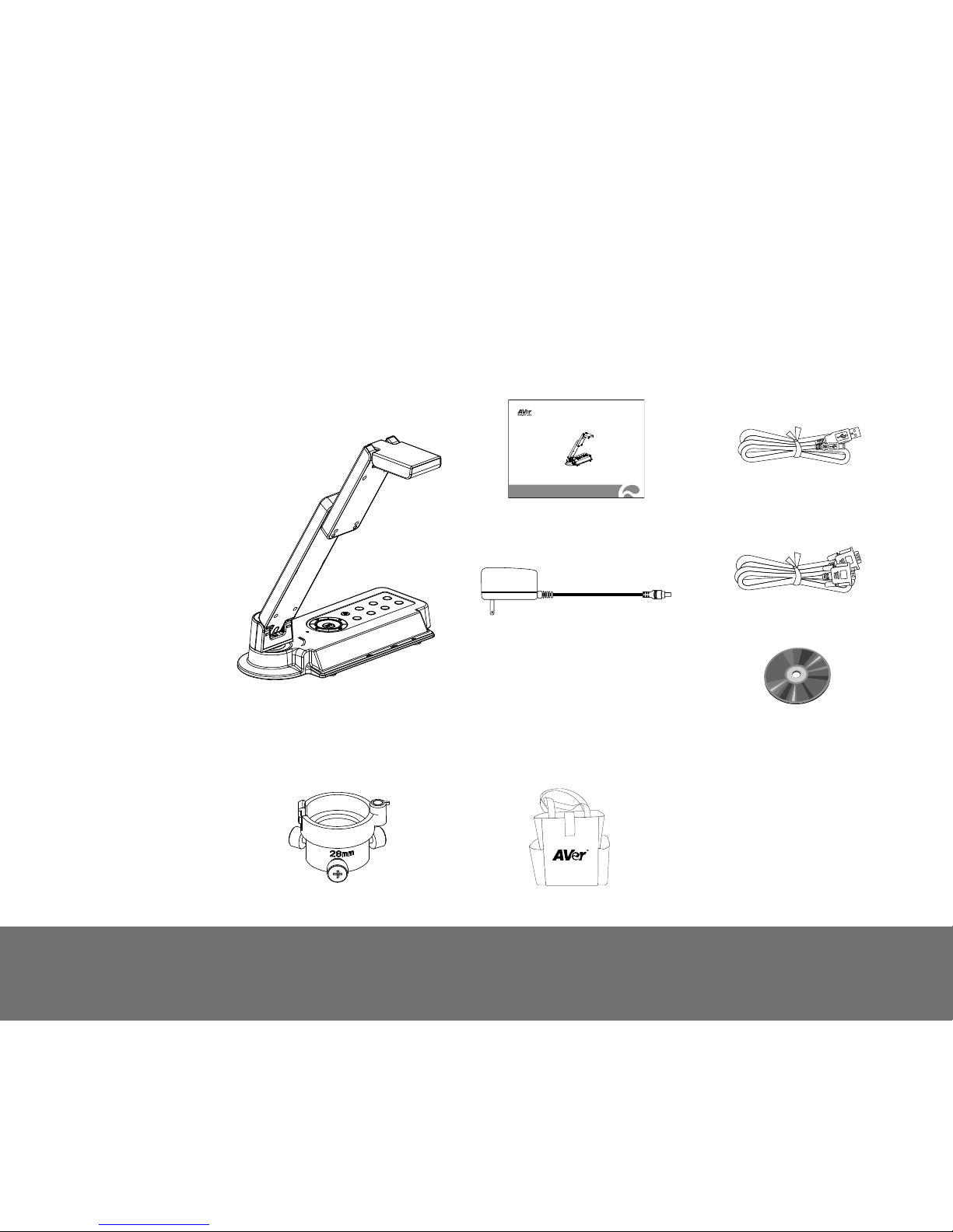
Package Contents .............................................................................................................................................................................. 1
Optional Accessories ........................................................................................................................................................................ 1
AVerVision VP-1HD Parts .................................................................................................................................................................. 2
Technical Specifications ................................................................................................................................................................... 3
Making the Connections.................................................................................................................................................................... 4
Connecting the Power Adapter.................................................................................................................................................... 5
Connect to a Monitor with HDMI Interface................................................................................................................................... 5
Connecting a RGB, Mac Display Monitor or LCD/DLP Projector................................................................................................. 6
Connecting a PC or Macintosh Computer ................................................................................................................................... 6
Connect to a Computer via USB.................................................................................................................................................. 7
Connecting to a Microscope ........................................................................................................................................................ 8
Setting Up AVerVision VP-1HD ....................................................................................................................................................... 10
Unfolding the Unit ...................................................................................................................................................................... 10
Operating Height & Angle ...........................................................................................................................................................11
Paper Guide ...............................................................................................................................................................................11
External Memory Storage .......................................................................................................................................................... 12
Touch Button Control Panel............................................................................................................................................................ 13
Control Panel Light Color................................................................................................................................................................ 14

OSD Menu......................................................................................................................................................................................... 15
Navigate the Menu and Submenu ............................................................................................................................................. 16
Image ........................................................................................................................................................................................ 17
Presentation .............................................................................................................................................................................. 19
Setting ....................................................................................................................................................................................... 22
System ...................................................................................................................................................................................... 26
Transfer Captured Images/Videos to a computer.......................................................................................................................... 29
Troubleshooting............................................................................................................................................................................... 30
Limited Warranty.............................................................................................................................................................................. 31

1
I
In
nt
tr
ro
od
du
uc
ct
ti
io
on
n
Thank you for purchasing
the AVerVision VP-1HD.
This document camera
displays documents,
transparencies and 3D
objects onto a TV, LCD or
DLP projector making
presentations a snap.
AVerVision VP-1HD is an
ideal presentation tool for
business, academic,
medical and the scientific
community.
P
Pa
ac
ck
ka
ag
ge
e
C
Co
on
nt
te
en
nt
ts
s
AVerVision VP-1HD
AVerVision VP-1HD
User Manual
User Manual
USB Cable
Power Adapter
* The power adapter will vary
depending on the country where it is
sold
RGB Cable (VGA Cable)
Software CD
O
Op
pt
ti
io
on
na
al
l
A
Ac
cc
ce
es
ss
so
or
ri
ie
es
s
28mm Microscope Adapter
Bag

2
A
AV
Ve
er
rV
Vi
is
si
io
on
n
V
VP
P-
-1
1H
HD
D
P
Pa
ar
rt
ts
s
The illustrations below identify the parts of AVerVision VP-1HD.
(1) Camera head
(2) Camera lens
(3) Rear panel
(4) Control panel
(5) Right panel
(6) Paper guide
(7) Bulit-in MIC
(8) Arm
(9) HDMI port
(10) DC 12V port
(11) RGB output port
(12) RGB input port
(13) USB OTG port
(14) OTG-USB switch
(15) Mini USB port
(16) Antitheft slot
(8)
(4)
(1)
(2)
(6)
(3)
(5)
(7)
Right Panel
(15)
(13)
(16)
(14)
Rear Panel
(9)
(10) (11)
(12)

3
T
Te
ec
ch
hn
ni
ic
ca
al
l
S
Sp
pe
ec
ci
if
fi
ic
ca
at
ti
io
on
ns
s
Image
Sensor 1/4" CMOS color image sensor
Total Pixels 5 Mega Pixels
Frame Rate
30 fps (max.)
15fps (1080p)
30fps (720p)
Analog RGB output
1920x1080,
1366x768
(VESA)(Panasonic_Japan),
1280x720,
1280x1024,
1280x800,
1600x1200,
1024x768
Optics
Lens F 2.8; fl=3.38mm
Focusing Auto
Zooming Digital Zoom: 16X
Shooting Area 340mm x 255mm
Input/Output
RGB Input 15-Pins D-sub (VGA)
RGB Output 15-Pins D-sub (VGA)
OTG port USB Type A
Mini USB 1394 interface
HDMI port HDMI
DC 12V Input Power Jack
Dimension
Operating 275mm(L) x 114mm(W) x 335mm(H)
Folded 275mm(L) x 114mm(W) x 70mm(H)
Weight 1.2 kg (about 2.64 lb)
Power
Power Source 100-240V, 50-60Hz
Consumption 7.8 Watts

4
M
Ma
ak
ki
in
ng
g
t
th
he
e
C
Co
on
nn
ne
ec
ct
ti
io
on
ns
s
The ports on the rear and right panel of VP-1HD enable you to connect the unit to a computer; graphics display monitor or LCD/DLP projector, TV or
other device. Illustrated below are the ports and switches that are located at the rear, and right panel of VP-1HD with their corresponding labels.
(2) (3)
(1)
(5)(6)(7)
(4)
(8)
Port Description
(1) DC 12V Connect the power adapter into this port.
(2) HDMI Port Output the video signal from the camera on an LCD
monitor with HDMI interface using HDMI cable.
(3) RGB OUT Output the signal from the camera, or RGB IN port on a
VGA/Mac monitor or LCD/DLP projector.
(4) RGB IN Input the signal from a computer or other sources and pass
it through to the RGB OUT port only.
Connect this port to the VGA output port of the computer.
(5) OTG Port To connect external USB flash drive for data storage (ex:
record video, capture image…etc.)(Also see External
Memory Storage section).
(6) OTG-USB Switch Switch function from OTG port to mini USB port.
(7) Mini USB Port Connect to a mini USB port of a computer with a USB
cable and use AVerVision VP-1HD as a USB Camera or
transfer the captured images/videos either from the
memory source to computer.
(8) Antitheft Slot Attach a Kensington compatible security lock or antitheft
device.

5
C
Co
on
nn
ne
ec
ct
ti
in
ng
g
t
th
he
e
P
Po
ow
we
er
r
A
Ad
da
ap
pt
te
er
r
Connect the power adapter to a standard 100V~240V AC power source.
Power adapter
Wall outlet
C
Co
on
nn
ne
ec
ct
t
t
to
o
a
a
M
Mo
on
ni
it
to
or
r
w
wi
it
th
h
H
HD
DM
MI
I
I
In
nt
te
er
rf
fa
ac
ce
e
Locate the HDMI input port of the display device and connect it to HDMI port of AVerVision VP-1HD.
HDMI monitor
HDMI cable

6
C
Co
on
nn
ne
ec
ct
ti
in
ng
g
a
a
R
RG
GB
B,
,
M
Ma
ac
c
D
Di
is
sp
pl
la
ay
y
M
Mo
on
ni
it
to
or
r
o
or
r
L
LC
CD
D/
/D
DL
LP
P
P
Pr
ro
oj
je
ec
ct
to
or
r
Locate the RGB input port of the display device and connect it to RGB OUT port of VP-1HD. If you are not sure, please refer to the user manual of the
device. Make sure the TV/RGB switch is set to RGB.
RGB cable LCD/DLP projector
LCD / MAC monitor
C
Co
on
nn
ne
ec
ct
ti
in
ng
g
a
a
P
PC
C
o
or
r
M
Ma
ac
ci
in
nt
to
os
sh
h
C
Co
om
mp
pu
ut
te
er
r
Locate the VGA output port of the computer or laptop to display your PC presentation on screen and connect it to RGB INPUT port of VP-1HD. The video
signal from the RGB IN port is streamed to RGB OUT port and displayed on the screen.
RGB cable
Computer
Laptop
MAC

7
C
Co
on
nn
ne
ec
ct
t
t
to
o
a
a
C
Co
om
mp
pu
ut
te
er
r
v
vi
ia
a
U
US
SB
B
Locate the USB port of the computer or laptop and connect it to USB port of AVerVision VP-1HD. This enables you to use AVerVision VP-1HD as a USB
Camera or to transfer the captured pictures/videos from the memory and to computer. Also see “Transfer Capture Images/Videos to a Computer”.
Make sure the OTG-USB switch is set to the left.
USB cable
Desktop
Laptop

8
C
Co
on
nn
ne
ec
ct
ti
in
ng
g
t
to
o
a
a
M
Mi
ic
cr
ro
os
sc
co
op
pe
e
Connecting the VP-1HD to a microscope enables you to examine microscopic objects on a big screen without straining your eyes.
1. Change the image display mode to Microscope. Press MENU >
select IMAGE tab > select MODE > select (microscope)
and
press .
2. Adjust the focus of the microscope.
3. Select the appropriate rubber coupler size for the microscope
eyepiece and insert it in the microscope adapter.
4. Remove the microscope eyepiece from the microscope and connect
it to the microscope adapter with the rubber coupler inserted. Fasten
the 3 bolts until the adapter secures the eyepiece.
For the eyepiece, we suggest using 15.5mm eye relief or higher.

9
5. Attach the microscope adapter to the AVerVision camera head.
Then connect it to the AVerVision and microscope.
5. Microscope
Adapter
Microscope
4. Microscope
eyepiece

10
S
Se
et
tt
ti
in
ng
g
U
Up
p
A
AV
Ve
er
rV
Vi
is
si
io
on
n
V
VP
P-
-1
1H
HD
D
This section provides useful tips on how to setup the VP-1HD to meet your needs.
U
Un
nf
fo
ol
ld
di
in
ng
g
t
th
he
e
U
Un
ni
it
t
Follow the step by step procedure below to setup the unit.
(1) Unfold the arm. (2) Turn 90° to the left. (3) Swivel up to the left. (4) Fold the camera down.

11
O
Op
pe
er
ra
at
ti
in
ng
g
H
He
ei
ig
gh
ht
t
&
&
A
An
ng
gl
le
e
The approximate height of the arm should be 335mm and angled at 53° to display an A4 size
landscape document.
P
Pa
ap
pe
er
r
G
Gu
ui
id
de
e
The A4 paper marks serve as a guide for placing the A4 document under the camera. The approximate shooting area of VP-1HD is 340mm x 255mm.
255 mm
340 mm
255 mm 340 mm

12
E
Ex
xt
te
er
rn
na
al
l
M
Me
em
mo
or
ry
y
S
St
to
or
ra
ag
ge
e
AVerVision VP-1HD supports USB flash drive for more image capture and audio & video recordings. AVerVision VP-1HD can detect when there is an
external storage media and automatically switch to the last detected storage. If no external storage is connected, all captured still images will be saved in
the built-in memory.
I
In
ns
se
er
rt
t
a
a
U
US
SB
B
F
Fl
la
as
sh
h
D
Dr
ri
iv
ve
e
Make sure to set the USB Flash Drive switch o the right before inserting a USB flash drive. AVerVision VP-1HD can support USB flash drive from 2GB to
32GB (FAT).
USB Flash Drive
OGT-USB switch
1
2

13
T
To
ou
uc
ch
h
B
Bu
ut
tt
to
on
n
C
Co
on
nt
tr
ro
ol
l
P
Pa
an
ne
el
l
The touch button control panel located on the top side of the VP-1HD provides quick access to commonly used functions.
AUTO
(1) (2) (3) (4)
(8)(11) (7) (6) (5)
(10)
(9)
Function Description
(1) POWER Turn the unit on/standby. To turn off, press hold POWER button for 5 sec.
(2) PC/CAM Switch between Camera and PC mode.
- Camera mode displays the video signal from the built-in camera.
- PC mode displays the video signal from the RGB IN port of VP-1HD.
(3) ROTATE Flip the image vertically, horizontally, rotate by 180°, and then return to normal view in camera mode only.
(4) FREEZE/STOP - Pause or resume image display in Camera mode.
- Stop audio & video playback in Playback mode.
(5) RECORDING Start/Stop audio & video recording.
(6) CAP/DEL - Capture picture in Camera mode. In continuous capture mode, press this button again to stop.
- Delete the selected picture/video in Playback mode.

14
Function Description
(7) PLAYBACK View & playback captured still images and audio video files. Press PLAYBACK button, the screen will switch to
playback mode. Press ►, ◄, ▼, and▲to choose a selection in the playback list. To Exit playback mode, press
PC/CAM button.
(8) MENU Open and exit the OSD menu.
(9) AUTO Automatically adjust the focus and set the white balance.
(10) Zoom( /) Digitally zoom in and zoom out the picture up to 1600%.
(11) Gain( /) Make image brighter or darker.
C
Co
on
nt
tr
ro
ol
l
P
Pa
an
ne
el
l
L
Li
ig
gh
ht
t
C
Co
ol
lo
or
r
The LED on the control panel of VP-1HD indicates the status of the unit.
Status
Output Power Up Power On Freeze Standby PC Mode
RGB Red (Flash) Green Green (Flash) Red Red
Other manuals for AVerVision VP-1HD
1
Table of contents
Other AVer Document Camera manuals

AVer
AVer AVerVision F70W User manual

AVer
AVer AVerVision F50HD User manual

AVer
AVer M5 User manual

AVer
AVer Vision F50 User manual

AVer
AVer AVerVision M70 User manual

AVer
AVer AVerVision SPB350+ User manual

AVer
AVer M15W User manual

AVer
AVer U70 Quick start guide

AVer
AVer M90UHD User manual

AVer
AVer M70W User manual

AVer
AVer AVerVision A30 User manual

AVer
AVer M90UHD User manual

AVer
AVer M70W User manual

AVer
AVer AVerVision300AF+ User manual

AVer
AVer AVerVision U70+ User manual

AVer
AVer AVerVision F17-8M User manual

AVer
AVer TabCam User manual

AVer
AVer M15W User manual

AVer
AVer AVerVision F series User manual

AVer
AVer M90UHD User manual