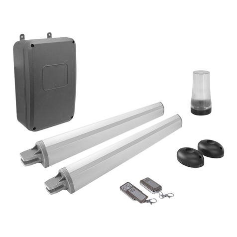
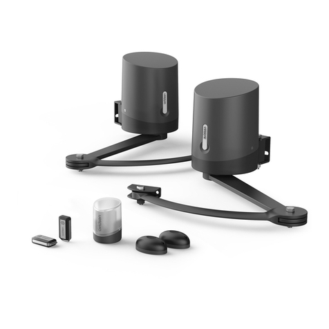
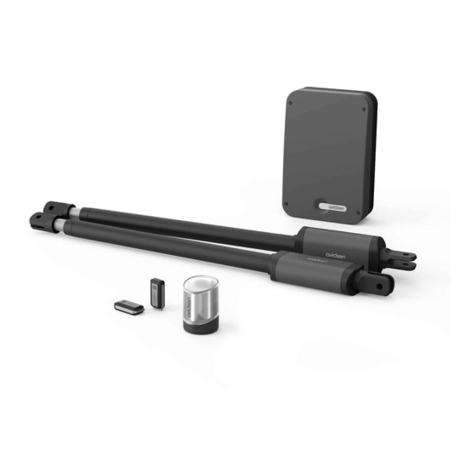
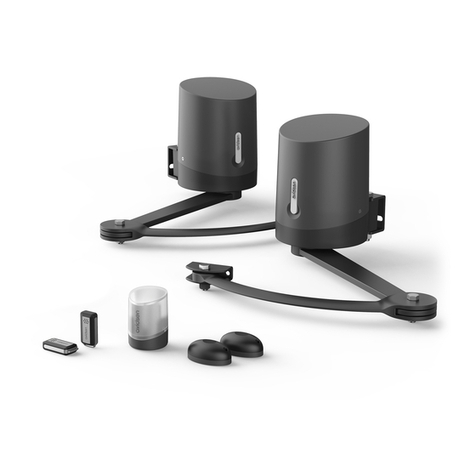
Avidsen Styrka 310 User manual

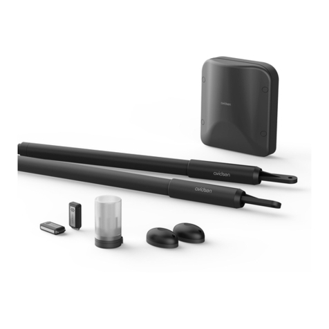
TELESCOPIC MOTOR DRIVE KIT
FOR 2-PANEL SWING GATES
Styrka 310
EN Ref.114170
www.avidsen.com
V4
24V OPENING
PANEL
2.50M
PER PANEL
2.20M
MAXIMUM
150KG
PER PANEL
COMPATIBLE WITH
WITH ALL TYPES
OF OPENWORK GATES
SOLAR
OPTION
SMARTPHONE
COMPATIBLE
OPTION
PHOTOCELL
OPTION
KG
L
H
TECHNICAL
SUPPORT
WARRANTY
3
YEARS

CONTENTS
A - SAFETY
INSTRUCTIONS
1 - OPERATING PRECAUTIONS 04
2 - INSTALLATION PRECAUTIONS 04
3 - MAINTENANCE AND CLEANING 05
4 - RECYCLING 05
B - PRODUCT
DESCRIPTION
1 - CONTENTS OF THE KIT 06
2 - EQUIPMENT REQUIRED (NOT INCLUDED)
06
C - INSTALLATION
1- HAZARD ANALYSIS 07
1.1- Regulations 07
1.2- Specifications of the gate to motorise 07
1.3- Safety check on the gate 07
1.4- Safety rules 08
2 - ELIMINATING HAZARDS 08
3 - INSTALLING THE MOTORS 09
4 - INSTALLING THE SWITCHGEAR 15
5 - INSTALLING THE FLASHING LIGHT 15
6 - INSTALLING THE SET OF PHOTOCELLS
(OPTIONAL) 16
7 - CONNECTIONS 18
7.1 - The mains electricity 19
7.2 - Telescopic motors 20
7.3 - Flashing light 20
7.4 - Photocells (optional) 21
7.5 - Control parts (optional) 21
7.6 - Backup battery (optional) 22
7.7 - Solar power kit (optional) 22
D - BEGINNING
OPERATION
1 - SETTINGS INTERFACE 23
2 - BASIC SETTINGS (MENU 1) 23
2.1 - Menu structure 23
2.1.1 - Basic settings menu (MENU 1) 24
2.2 - Photocell alignment procedure
(optional) 25
2.3 - Operating mode 25
2.4 - Time delay 25
2.5 - Motor force 26
2.6 - Speed 26
2.7 - Self-learning 26
2.8 - Programming remote controls 28
2.8.1 - Programming with the card 28
2.8.2 - Copy programming 28
2.8.3 - Deleting all remote controls 29
3 - ADVANCED SETTINGS 29
3.1 - Accessing the advanced settings
(menus 2 and 3) 29
3.2 - Advanced settings menu (menu 2) 30
3.2.1 - Acceleration 30
3.2.2 - Photocell mode 30

3.2.3 - Type of gate 31
3.2.4 - Stop tolerance 31
3.3 - Advanced settings menu (menu 3) 32
3.3.1 - Panel movement time interval 32
3.3.2 - Pre-flashing time 32
E - USE
1 - WARNINGS 34
2 - OPENING/CLOSING 34
3 - TYPE OF COMMAND 34
4 - OPERATING MODES 34
4.1 - “Semi-automatic closing” mode 35
4.2 - “Automatic closing” mode 35
4.3 - “Collective” mode 35
5 - PHOTOCELLS 35
5.1 - Obstacle detection 36
6 - MANUAL MOVEMENT 36
7 - OPTIONAL ACCESSORIES 37
F - MAINTENANCE
AND UPKEEP
1 - MAINTENANCE WORK 38
2 - OPERATING INDICATORS 39
2.1 - History of events and error codes 39
2.2 - Manual control 41
2.3 - Total reset 41
2.4 - Replacing the remote control battery 41
2.5 - Replacing the power fuse 42
G - TECHNICAL
AND LEGAL
INFORMATION
1 - TECHNICAL CHARACTERISTICS 43
2 - WARRANTY 45
3 - HELP AND ADVICE 45
4 - PRODUCT RETURNS/AFTER SALES
SERVICE 45
5 - DECLARATION OF CONFORMITY 45

EN5EN 4
A - SAFETY INSTRUCTIONS
In our efforts to continually improve our products,
we reserve the right to make any changes to the
technical, functional, or aesthetic characteristics
related to their development.
This automatic gate opening mechanism, and
its manual, were designed to enable a gate to be
motorised in compliance with current European
standards.
WARNING
Important safety instructions. A automatic gate
opening mechanism is a product that can cause
injury to people and animals and damage to
property. It is important for people’s safety to follow
these instructions.
Keep these instructions.
1 - OPERATING PRECAUTIONS
• This apparatus may be used by children over
the age of 8 and by persons with reduced
physical, sensory or mental abilities or lack of
experience or familiarity, if they are correctly
supervised or if the instructions relating to the
safe use of the apparatus have been given to
them and the possible hazards are understood.
Children must not play with the device.
Cleaning and user maintenance must not be
conducted by children without supervision.
• This apparatus should only be used for its
intended purpose, that is, to motorise a one-
or two-panel gate for vehicle access. Any other
use will be considered dangerous.
• The opening or closing manoeuvre control
must be used with perfect visibility of the gate.
Should the gate be outside the user’s field of
vision, the installation must be protected by a
photocell type safety device, and its operation
must be checked every six months.
• All potential users must be instructed in the use
of the motorised gate by reading this manual. It
must be ensured that no persons who have not
been instructed in the use of the device may
set the gate into motion.
• Before setting the gate into motion, ensure that
there is no person in the area in which the gate
moves.
• Do not let children play with the gate control
devices. Keep the remote controls out of the
reach of children.
• Avoid any natural obstacles (branch, stone, high
grass, etc.) impeding the gate’s movement.
• Do not manually activate the gate when the
motor drive is not disengaged from the gate.
Avidsen cannot be held liable for any use that does
not comply with the instructions in this manual and
causes damage.
2 - INSTALLATION PRECAUTIONS
• Read this entire manual before starting the
installation.
• The electrical installation of the motorised
gate must meet current standards (NF C 15-
100) and should be undertaken by a qualified
person.
• The 230VAC mains supply must be protected
with a suitable circuit breaker which meets
current standards.
• All electrical connections must be performed
with the power switched off (safety switch in
the OFF position) and battery disconnected.
• Ensure that crushing and shearing between
the mobile parts of the motorised gate and
the surrounding fixed parts due to the gate’s
opening/closing movement are avoided or
signalled on the installation.
• The motorised part must be installed on a gate
according to the specifications provided in this
manual.
• The motorised gate must not be installed in
an explosive atmosphere (presence of gas,
flammable smoke, etc.).
• The installer must check that the temperature
range shown on the motor drive is suitable for
the location.
• The wire that acts as an antenna must remain
inside the electronic panel.
• It is strictly forbidden to modify any of the
components provided in this kit, or to use an
additional component not provided for in this
manual.
• During installation, but above all during
adjustment of the motorised gate, you must
ensure that no person, including the installer, is
in the area in which the gate moves at the start
and throughout the duration of adjustment.
• The flashing light is an essential safety
component.
• If installation does not correspond to one of the
cases shown in this manual, you must contact
us so that we can provide all the components

EN5EN 4
A - SAFETY INSTRUCTIONS
necessary for smooth installation with no risk of
damage.
• After installation, ensure that the mechanism
is correctly adjusted and that the protection
systems work correctly.
• Do not let children play with the fixed control
devices. Keep the remote controls out of the
reach of children.
The Avidsen company shall not be responsible in
case of damage if installation is not conducted as
indicated in these instructions.
3 - MAINTENANCE AND CLEANING
• Read all the instructions given in this manual
before carrying out maintenance on the
motorised gate.
• Disconnect the power supply during cleaning
or other maintenance operations if the device
is automatically controlled.
• Any technical, electronic or mechanical change
to the motorised gate must be made with our
technical department’s approval; otherwise,
the guarantee will be immediately cancelled.
• In the event of breakdown, the damaged part
should be replaced by an original part and
nothing else.
• Check the installation frequently to reveal any
fault on the gate or the motor drive (see the
chapter on maintenance).
• Never use abrasive or corrosive substances to
clean the products.
• Use a soft, slightly damp cloth.
• Never use an aerosol to spray the product as
this may damage the internal workings.
• Do not clean with a pressure washer.
4 - RECYCLING
Disposing of used batteries in household
waste is strictly forbidden. Batteries/
accumulators containing harmful
substances are marked with symbols
(shown opposite) which indicate that it is
forbidden to discard them in the household waste.
The corresponding heavy metals are referred to as
follows: Cd= cadmium, Hg= mercury, Pb= lead.
You can dispose of these batteries/accumulators at
local waste treatment centres (centres for sorting
recyclable materials) who are under an obligation
to recover them. Keep batteries/button cells/
accumulators out of reach of children and store
them in a safe place not accessible to them. They
could be swallowed by children or pets. Risk of
death! If they
should be swallowed in spite of all the precautions,
consult a doctor or go to A&E immediately. Never
short-circuit the batteries, and do not burn or
recharge them as they may explode!
Pour en savoir plus :
www.quefairedemesdechets.fr
This logo denotes that devices no longer in
use should not be disposed of as
household waste. They are likely to contain
hazardous substances which are
dangerous to both health and the
environment. Return the equipment to your local
distributor or use the recycling collection service
provided by your local council.

EN7EN 6
B - PRODUCT DESCRIPTION
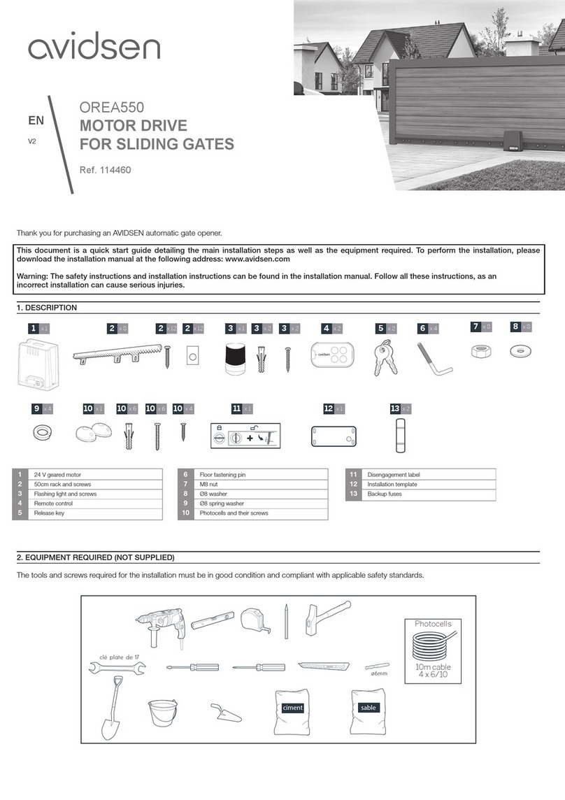
1 - CONTENTS OF THE KIT
2 - EQUIPMENT REQUIRED (NOT INCLUDED)
The tools and screws required for the installation must be in good condition and compliant with applicable
safety standards.
¡
¡
¡
[ [
¡
¡ ¡[
¡
[ [
¡[
IL[DWLRQGHVSDWWHV
VXUOHSRUWDLO
&KRLVLUXQV\VWqPH
YLVpFURXVDGDSWpj
O¶pSDLVVHXUGXSRUWDLO
,O\DSRLQWVGHIL[DWLRQ
¡
drilling the
post
flashing light motor attachment to the
post:
- electronic panel
- flashing light
attachment of the
brackets
onto the posts:
3m cable
2 x 0.5mm2 10m cable
2 x 1.5mm2
drilling into
the gate
9x 1
8x 2
1x 1 3x 4 4x 2
2x 1
5x 1
5x 1 6x 4 7x 4
1Telescopic motors 24V
2Switchgear
3Post mounting bracket
4Gate mounting bracket
5Clevis pins
6Spacer
7Elastic pin
8Remote control
9Flashing light

EN7EN 6
C - INSTALLATION
1 - HAZARD ANALYSIS
1.1 - Regulations
Installation of a motorised gate or a motor drive on
an existing gate within the framework of “Residential”
type use must be compliant with Regulation (EU)
305/2011 concerning building products.
The reference standard used to check this
compliance is EN 13241-1 which refers to a
framework of several standards including EN 12445
and EN 12453 which specify the motorised gate
safety methods and components to reduce or
completely eliminate hazards to people.
The installer must train the end user on the correct
operation of the motorised gate, and the trained
user must train the other people likely to use the
motorised gate, using this guide.
It is specified in standard EN 12453 that the
minimum protection of the gate’s primary edge
depends on the type of use and the type of control
used to set the gate in motion. The gate motor drive
is a press control system, i.e. simply pressing one of
the control parts (remote control, key selector, etc.)
sets the gate in motion.
This gate motor drive is equipped with a force
limiter which complies with appendix A of EN 12453
standard, within the framework of use with a gate
that is compliant with the specifications given in this
chapter. The specifications of EN12453 standard
therefore enable the 3 following use cases, as well
as the minimum levels of protection:
• Press activation with non-visible
gate
Minimum level of protection: Force limiter only.
• Press activation with non-visible
gate
Minimum level of protection: Force limiter and 2
pairs of photocells to protect the gate’s opening
and closing.
• Automatic control (automatic
closure)
Minimum level of protection: Force limiter and 1 pair
of photocells to protect the gate’s automatic closing.
The flashing light is an essential safety component.
The proper operation of the safety devices must be
checked every six months.
1.2 - Specications of the gate to motorise
This motor drive can automate swing gates up to
2.50m wide and 2.20m high and weighing 150kg.
These maximum dimensions and weights are for an
openwork-type gate and for use in an area that is
not very windy. For use in an area with significant
wind speed, it is necessary to reduce the maximum
values indicated above for the gate to be motorised.
1.3 - Safety checks on the gate
The motorised gate is strictly for residential use.
The gate must not be installed in an explosive or
corrosive atmosphere (presence of gas, flammable
smoke, vapour or dust).
The gate must not have locking systems (latch, lock,
bolt, etc.).
The hinges of the gate must be on the same axis and
the axis must be vertical. The posts supporting the
gate must be strong and stable enough so that they
do not bend (or break) under the weight of the gate.
Without the motor drive, the gate must be in good
mechanical conditions, correctly balanced and open
and close without friction or resistance. Greasing the
hinges is recommended. Check that the fastening
points of the different components are in locations
that are sheltered from shock and that the surfaces
are solid enough. Check that the gate does not have
any part protruding from its structure. The central
stop and side stops must be appropriately fastened
so as not to give way under the force exerted by the
motorised gate.
If installation does not correspond to one of the
cases shown in the guide, contact us so that we can
provide all the components necessary for proper
installation with no risk of damage.
The motor drive cannot be used with a driven part
that has a door.

EN9EN 8
C - INSTALLATION
1.4 - Safety rules
The actual opening of a gate may create dangerous situations for people, goods and vehicles in the vicinity
that by nature, cannot always be avoided by design.
The possible hazards depend on the state of the gate, the manner in which it is used and the installation site.
After having checked that the gate to be motorised complies with the requirements given in this chapter and
before beginning the installation, a hazard analysis of the installation must be conducted in order to eliminate
all dangerous situations or to indicate them if they cannot be eliminated.
2 - ELIMINATING HAZARDS
The hazards posed by a two-panel motorised gate, as well as the adapted solutions to eliminate those
hazards, are as follows:
Subpanels
Following installation, there may be a shear zone between the panel and the corner of the post.
In this case, it is recommended to remove this zone leaving a minimum working distance of 25 mm either
by positioning the side stops accordingly or by notching the corner of the posts without weakening them, or
both if necessary.
If this is not possible, the hazard must be clearly reported.
hazard
view from above
solution
post
shear
zone
stop
view
stop
view
stop
view
25 mm
minimum
25 mm
minimum
post post
Bottom edges
Following installation, there may be a dangerous zone for toes between the bottom edge of the gate and the
ground, as indicated in the following figure.
In this case, this area must be removed leaving a working distance of minimum 50mm or maximum 5mm.

EN9EN 8
C - INSTALLATION
hazard
view in profile
solution
opening opening opening
hazardous zone
50mm
minimum
5mm
minimum
Between the panels and the fixed parts close to each other
Depending on the configuration of the site where the motorised gate is installed, there may be confinement
areas between the panels in open position and the fixed parts close to them. To remove these areas, it is
mandatory to leave a safe distance of 500mm between the fixed part and the moving parts of the motorised
gate.
hazard
view from above
solution
post
confinement
area
500mm
minimum
post
PREVENTING OTHER HAZARDS
The body of a switch with no lock must be located in direct view of the driven part but away from moving
parts. Unless it operates with a key, it must be installed at a minimum height of 1.5 m and must not be
accessible to the public.
After installation, ensure that the components of the gate do not hang above a footpath or public access road.
3 - INSTALLING THE MOTORS
The motor drive must be installed by qualified personnel, in compliance with all the indications provided in the
“General warnings.”
Before starting installation, ensure that:
• Hazards can be minimised by following the recommendations under the Chapter “Hazard analysis.”
• The desired use has been correctly defined.
• The gate complies with the specifications provided in the Chapter “Specifications of the gate to motorise.”
The different stages of installation must be followed in order and in compliance with the indications given.

EN11EN 10
C - INSTALLATION
• The use of stops is mandatory (not provided)
This gate motor drive is a self-locking motorisation system. Your 2-panel gate must be equipped with a central
stop and side stops (not included).
The (central and side) stops must stop the gate without locking it. In other words, any mechanical lock (or
latch) and any tilting shoe base or stopper must be removed.
The installation of the side stops depends on the desired opening angle which depends on distance D (the
distance between the axis of the hinge and the inner side of the post).
D
D
positive distance D
negative distance D
view from above
view from above
post
post
If the positive distance Dis greater than 190 mm or if distance Dis negative, the configuration of the posts
must be adjusted.
Special cases
• If D>190mm and if the structure of the posts allows, the posts must be cut so that D’is equal to
190mm.
D’
post
• If D<0mm, place a shim thick enough so that D’ is equal to 0mm.
D’
post

EN11EN 10
C - INSTALLATION
Determine the opening angle of each panel based on the data in the following table.
The opening angle may be different for each panel but must never be less than 40°.
For
opening up to
Distance D
(in mm)
90° from 0 to 190 max
95° from 0 to 160 max
100° from 0 to 140 max
105° from 0 to 120 max
110° from 0 to 90 max
120° from 0 to 30 max
DD
central stop
Inner side of the property
view from above
opening
angle
opening
angle
stop
view
Overview
telescopic motors
Mandatory central stop
(not included)
Mandatory side stops
(not included)
Inner side of the property
Flashing light
Switchgear
control unit

EN13EN 12
C - INSTALLATION
Attaching the post mounting bracket
Mount the motors to a rigid and reinforced part of the gate (e.g. the frame or the crossbar). Mount them as
low as possible for aesthetic and technical reasons.
CORRECT IDEAL
The instructions below describe installation of the left motor; to install the right motor, repeat the process while
respecting the symmetry.
• Measure distance D, then refer to the table for distance B, which allows you to determine the post mounting
bracket position. The table also indicates the hole in which the motor will be mounted.
• The height of the centre of the mounting bracket must be the same as the centre of the gate frame on which
the motor is mounted.
70
mm
D
B
post
B
D(mm) B(mm) max angle (°)
0220 120°
30 220 120°
60 210 110°
90 190 110°
120 190 105°
140 180 100°
160 170 95°
180 160 90°
190 160 90°
Mark the location of the holes in the post, ensuring that the post mounting bracket is mounted horizontally at
the end. Use 10-inch lag screws or any other fastening system suitable for the post material.

EN13EN 12
C - INSTALLATION
Please note: there will be significant force on the mounting bracket when the motor drive is running. We
recommend sealing threaded rods at least 15 cm in length. If the post is made of metal, we recommend
welding or passing the threaded rods through to secure them with self-locking nuts.
Consult a professional if in doubt.
Attaching the gate bracket to the motor
Assembling the motor to the post bracket
Please note: the motor must be turned so that the wire is at the bottom
Remember to add the spacers on both sides of each mounting bracket.

EN15EN 14
C - INSTALLATION
Positioning of the bracket on the gate
To position the motor on the gate, the motor rod must be retracted 20mm from its fully extended position. If
this distance is not strictly observed, the motors may experience operating problems that are not
covered by the product warranty.
• Unscrew the motor rod by hand to get it all the way out.
• Make a mark on the inner tube 20 mm from the outer tube as shown in the drawing below:
20mm
tube intérieur
20mm
• Screw the 20 mm inner tube back on using the previously made mark; push the tube in until the mark
disappears, but no further.
20mm
tube intérieur
20mm
• Close the gate and place the mounting bracket on the crossbar of the gate, making sure that the motor is
horizontal, then mark the location of the two holes to be drilled in the gate.
Once the holes are drilled, remove the gate mounting bracket from the motor by removing the pin. Attach the
bracket to the gate, preferably using through-bolts.
• Reassemble the motor and the gate mounting bracket.

EN15EN 14
C - INSTALLATION
4 - INSTALLING THE SWITCHGEAR
The switchgear must be mounted to the post where the 230Vac power comes from.
• To ensure proper operation of the motorisation, the length of the motor cables must not exceed 8 m per
motor. The cables must have sections of at least 1.5mm. Therefore, the switchgear must be mounted less
than 6m from each motor.
•Use four screws and dowels to install and mount the switchgear in the defined location.
5 - INSTALLING THE FLASHING LIGHT
The flashing light must be fastened at the top of the post on which the switchgear is attached and must be
visible both inside and outside. Only use the light provided in the kit (24 V - 2 W).
The flashing light may be fastened on the wall with or without support.
• With a screwdriver, remove the transparent part of the flashing light by unscrewing the 2 screws that hold
the upper part of the flashing light.
• Still with a screwdriver, remove the flashing light bracket by unscrewing the 2 screws inside the light.
• Fasten the flashing light bracket to the wall (ignore this step if you are fastening the light directly to the wall).
• Run the wires into the flashing light and connect them to the LED lightbulb (maintaining the “+” and “-”
polarity).
• Screw the flashing light to its bracket and screw in the transparent part

EN17EN 16
C - INSTALLATION
6 - INSTALLING THE SET OF PHOTOCELLS (OPTIONAL)
1 set of photocells
• Install the reception photocell (RX indicated at the back) of the same side of the gate as the switchgear. The
surface of the posts must be perfectly flat in order to properly align the infrared beam of the photocells.
• Place the photocells at exactly the same height from the ground; they must be perfectly aligned and parallel
to each other.
The distance between the outer side of the gate and the photocells must be between 10cm and 15cm.
• Mount the photocells on the posts.

EN17EN 16
Outer side of the property
30cm min
60cm max
view from above
Inner side of the property
perfect alignment
10cm min
15cm max
Outer side of the property Outer side of the property Outer side of the property
45mm
20mm
C - INSTALLATION

EN19EN 18
C - INSTALLATION
7 - CONNECTIONS
• The cable run between must comply with applicable standards (NFC 15-100).
• Either the cable is 80cm deep with red warning mesh, or the cable is run through a sheath.
vers
230V
Safety instructions
• All electrical connections must be performed with the power switched off (safety switch in OFF position).
• These connections must be made by a qualified electrician.
• Remove the protective cover from the transformer.

EN19EN 18
7.1 - THE MAINS ELECTRICITY
Important notes:
• The electrical line may only be used to power the gate motor drive. It must be protected by a fuse or circuit
breaker (6A min., 16A max.) and a differential device (30mA). It must be
compliant with the applicable electrical safety standards.
• The 230V power cable must be HO5RN-F type.
• Connect the wires from the power supply and make sure they are properly secured in the terminal block.
Once the 230V cable has been run through the cable duct, replace the protective cover.
Phase
Neutral
C - INSTALLATION

EN21EN 20
C - INSTALLATION
7.2 - TELESCOPIC MOTORS
For motor wiring on the electronic card, use a 2x1.5mm² cable. Run the cable through the cable clamp and
tighten
• For opening towards the inside
Black
Red
L0
PROG OK
+
-
L1 L2 L3 L4 +-
BATTRANS
GND
GND
PHO
+24V
M1-
M2-
M1+
M2+
warn-
warn+
2B
M2M1
The motor that opens first must be
connected to the M1 output of the
electronic card.
Black Red
7.3 - FLASHING LIGHT
• Connect the flashing light wires to the terminal block as shown in the diagram below.
• Use a 2x0.5mm² section cable, at least.
• Maintain the connection polarity
L0
PROG OK
+
-
L1 L2 L3 L4 +-
BATTRANS
GND
GND
PHO
+24V
M1-
M2-
M1+
M2+
warn-
warn+
2B
This manual suits for next models
1
Table of contents
Other Avidsen Gate Opener manuals

Avidsen
Avidsen OREA550 User manual

Avidsen
Avidsen ORANGE510 User manual

Avidsen
Avidsen ZENIA250 User manual

Avidsen
Avidsen 114359 User manual

Avidsen
Avidsen ORANE410 User manual

Avidsen
Avidsen STYRKA310 User manual

Avidsen
Avidsen STYRKA400 User manual

Avidsen
Avidsen 114461 User manual

Avidsen
Avidsen V300 User manual

Avidsen
Avidsen ORANE510 User manual