AVL Looms A Series User manual

A-Series Dobby Loom
Assembly Manual
AVL Looms
2360 Park Avenue
Chico, CA 95928-6785
U.S.A.
530 893-4915
530 893-1372 (fax#)
[email protected](e-mail)
www.avlusa.com
v. 1.1
Copyright ©2019
All Rights Reserved Worldwide


A-Series Dobby Loom Assembly Manual Introductory Information
Introductory Information Page | i
Introductory Information ................................................................................................................ 1
Safety .......................................................................................................................................... 2
Introduction ................................................................................................................................. 4
Loom Features ............................................................................................................................ 4
Basics of Assembly ..................................................................................................................... 7
the Loom ..................................................................................................................................... 8
Frame Assembly ........................................................................................................................... 11
Loom Orientation ...................................................................................................................... 12
Tools Needed For Assembly ..................................................................................................... 12
Unpacking ................................................................................................................................. 13
Hardware Identification ............................................................................................................ 14
Side Frame Assembly ............................................................................................................... 16
Joining Side Frames .................................................................................................................. 21
Installing Treadles ..................................................................................................................... 23
Treadle Pulley Support (#12) .................................................................................................... 24
Installation of the E-Lift............................................................................................................ 26
Spring Lever / Spring Perch Assembly (#11) ........................................................................... 29
Squaring and Leveling the Frame ............................................................................................. 31
Install the Inner Workings ............................................................................................................ 33
Harness Pulley Support (#10) ................................................................................................... 34
Dobby Head Installation ........................................................................................................... 35
Treadle Tie-Up .......................................................................................................................... 40
Setting up the E-Lift Cables ...................................................................................................... 45
Attaching the Harness Cables ................................................................................................... 49
Heddles ..................................................................................................................................... 52
Installing Beams And Rollers ....................................................................................................... 59
Warp Beams .............................................................................................................................. 60
Install the Lower Warp Beam ................................................................................................... 61
Install the Upper Warp Beam ................................................................................................... 62
Installing the Separation Roller (#39) ....................................................................................... 63
Tension Arm Installation .......................................................................................................... 63
Installing the Cloth Beam ......................................................................................................... 71
Cloth Storage System ................................................................................................................ 72
Temple System (To Prevent Draw-In) ...................................................................................... 80

Introductory Information A-Series Dobby Loom Assembly Manual
Page | ii Introductory Information
Bottom Swing Beater .................................................................................................................... 83
Install Beater Bumpers .............................................................................................................. 84
Bottom Swing Beater Supports ................................................................................................. 85
Bottom Swing Beater ................................................................................................................ 86
Single-Box Flyshuttle Tie-Up (optional) .................................................................................. 90
Overhead Beater (Optional) .......................................................................................................... 93
Overhead Beater (optional equipment) ..................................................................................... 94
Overhead Single-Box Flyshuttle Beater Tie-Up (optional equipment) .................................. 105
Overhead Multi-Box Flyshuttle Beater (optional equipment) ................................................ 107
Vertical Pull Flystring Tie-Up ................................................................................................ 109
Two-Box Flyshuttle – Dropbox Movement ............................................................................ 112
Four-Box Flyshuttle Dropbox Movement .............................................................................. 114
Finish Setting Up Your Loom..................................................................................................... 119
Compu-Dobby Box ................................................................................................................. 120
Mechanical Dobby Setup ........................................................................................................ 123
E-Lift Operation ...................................................................................................................... 124
Assembling the Bench ............................................................................................................ 126
Appendix I: Optional Equipment ................................................................................................ 129
Raddle ..................................................................................................................................... 130
Tension Box ............................................................................................................................ 130
Auto Advance System ............................................................................................................. 133
Locking Brake ......................................................................................................................... 136
Bustle ...................................................................................................................................... 141
Appendix II: Air Assist Options ................................................................................................. 143
Air Component Information ................................................................................................... 144
Air Compressor Requirements ................................................................................................ 145
Installing the FRL ................................................................................................................... 146
Installing An A-Lift ................................................................................................................ 147
Installing an Air Shuttle .......................................................................................................... 152
Air Shuttle Operation .............................................................................................................. 160
Air Beater ................................................................................................................................ 161
Connecting the components to compressed air ....................................................................... 162
Maintaining Your System ....................................................................................................... 163
The Fine Print ............................................................................................................................. 165

A-Series Dobby Loom Assembly Manual Introductory Information
Introductory Information Page | iii
AVL Customer Service ........................................................................................................... 166
AVL Warranties ...................................................................................................................... 166
Notice to Users in the European Union .................................................................................. 167
List of Figures
Figure 1 - Full Loom - Left Side ..................................................................................................... 9
Figure 2 - Full Loom - Right Side ................................................................................................ 10
Figure 3 - Tools Needed for Assembly ......................................................................................... 13
Figure 4 - Hex Bolt ....................................................................................................................... 14
Figure 5 - Carriage Bolt ................................................................................................................ 14
Figure 6 - Flat Head Machine Screw ............................................................................................ 14
Figure 7 - Flat Washer .................................................................................................................. 14
Figure 8 - Hex Nut ........................................................................................................................ 14
Figure 9 - Square Nut .................................................................................................................... 14
Figure 10 - Wing Nut .................................................................................................................... 14
Figure 11 - Allen Wrench ............................................................................................................. 15
Figure 12 - Black Knob................................................................................................................. 15
Figure 13 - Measuring Bolts ......................................................................................................... 15
Figure 14 - Stop Collar ................................................................................................................. 15
Figure 15 - Inserting Nuts ............................................................................................................. 16
Figure 16 - Side Frame ................................................................................................................. 17
Figure 17 – Partially completed side frame .................................................................................. 18
Figure 18 - Top of side frame ....................................................................................................... 19
Figure 19 - Dobby Cam Assembly for E-lift ................................................................................ 20
Figure 20 - Dobby Cam and Pulley for treadles ........................................................................... 20
Figure 21 - A-Lift Pulleys ............................................................................................................. 20
Figure 22 - Lower Back Crossmember ......................................................................................... 21
Figure 23 - Upper Back Crossmember ......................................................................................... 22
Figure 24 - Loom on its back ........................................................................................................ 22
Figure 25 - Attaching front crossmember ..................................................................................... 23
Figure 26 - Treadles ...................................................................................................................... 24
Figure 27 - Treadle Pulleys ........................................................................................................... 25
Figure 28 - Lift Support ................................................................................................................ 26
Figure 29 - E-lift ........................................................................................................................... 27
Figure 30 - E-lift attached to supports .......................................................................................... 28
Figure 31 – Lock Washer .............................................................................................................. 29
Figure 32 - E-lift installed ............................................................................................................. 29
Figure 33 - Spring Lever Assembly .............................................................................................. 30
Figure 34 - 32/40 Harness Spring System .................................................................................... 30
Figure 35 - Measuring for square.................................................................................................. 31
Figure 36 - Leveling the loom ...................................................................................................... 32
Figure 37 - Harness Pulley Support .............................................................................................. 34
Figure 38 - Back of the Dobby ..................................................................................................... 35
Figure 39 - Mounting the Dobby .................................................................................................. 36

Introductory Information A-Series Dobby Loom Assembly Manual
Page | iv Introductory Information
Figure 40 - Dobby on the Loom ................................................................................................... 37
Figure 41 - Left side of the Mechanical Dobby with springs ....................................................... 39
Figure 42 - Dobby Cam and Pulley .............................................................................................. 40
Figure 43 - Treadle Pulleys ........................................................................................................... 41
Figure 44 - Bolt for the Treadle Cable .......................................................................................... 41
Figure 45 - Right Treadle Cables .................................................................................................. 42
Figure 46 - Dobby Cam with Turnbuckle ..................................................................................... 43
Figure 47 - Cam Cables ................................................................................................................ 45
Figure 48 - Slide Plate Eyebolt ..................................................................................................... 45
Figure 49 - Dobby Slide Plate to Spring Lever Cable .................................................................. 46
Figure 50 - Return Pulley Cable ................................................................................................... 46
Figure 51 - E-lift Spring Lever ..................................................................................................... 47
Figure 52 - Cable in Nautilus cam ................................................................................................ 48
Figure 53 - Secured Cable ............................................................................................................. 48
Figure 54 - Clip opened with pliers .............................................................................................. 49
Figure 55 - Berkeley Clips ............................................................................................................ 50
Figure 56 - Harness Cable Retainers ............................................................................................ 50
Figure 57 - Harness cables hanging on loom ................................................................................ 51
Figure 58 - Polyester Heddle Bundle ............................................................................................ 52
Figure 59 - Parallel Harness Sticks ............................................................................................... 54
Figure 60 - Harness Sticks with Heddles ...................................................................................... 54
Figure 61 - Harness wire ............................................................................................................... 55
Figure 62 - Metal Heddle Frame ................................................................................................... 56
Figure 63 - Beam Retainer ............................................................................................................ 61
Figure 64 - Warp Beam Handle .................................................................................................... 62
Figure 65 - Lower Warp Beam Tension ....................................................................................... 64
Figure 66 - Tension Arm Bolt ....................................................................................................... 65
Figure 67 - Lower Beam Tension Cord ........................................................................................ 66
Figure 68 - Upper Position Tension .............................................................................................. 67
Figure 69 - Tension Cable around Brake Drum ............................................................................ 68
Figure 70 - Upper Tension Tie-up ................................................................................................ 69
Figure 71 - Weight with wooden bracket removed ...................................................................... 70
Figure 72 - Tension Arm with Weight .......................................................................................... 70
Figure 73 - Cloth Beam Assembly................................................................................................ 71
Figure 74 - Right Side Cloth Beam Support ................................................................................. 72
Figure 75 - Pressure Roller Bracket .............................................................................................. 73
Figure 76 - Pressure Roller and Cloth Beam on Loom ................................................................. 74
Figure 77 - Cloth Storage System Rollers .................................................................................... 75
Figure 78 - Cloth Take-up Drum .................................................................................................. 75
Figure 79 - Cloth Storage Drum ................................................................................................... 76
Figure 80 - Routing the Cloth Take-up Cord ................................................................................ 77
Figure 81 - Knot on Cloth Take-up Drum .................................................................................... 78
Figure 82 - Cloth Storage Apron .................................................................................................. 79
Figure 83 - Pre-installed Hex Nuts ............................................................................................... 80
Figure 84 - Button Head Cap Screws ........................................................................................... 81
Figure 85 - Loosen Nut ................................................................................................................. 81
A-Series Dobby Loom Assembly Manual Introductory Information
Introductory Information Page | v
Figure 86 - Ring Temple from Front ............................................................................................ 82
Figure 87 - Beater Bumper Block ................................................................................................. 84
Figure 88 - Beater Support ............................................................................................................ 85
Figure 89 - Bottom Swing Beater Support ................................................................................... 86
Figure 90 - Beater Leg .................................................................................................................. 87
Figure 91 - Single-box Flyshuttle Beater ...................................................................................... 89
Figure 92 - Beater Reed Support .................................................................................................. 90
Figure 93 - String tie-up and handle ............................................................................................. 91
Figure 94 - Axle Block on loom ................................................................................................... 94
Figure 95 - Beater Retainer ........................................................................................................... 95
Figure 96 - Beater Retainer ........................................................................................................... 95
Figure 97 - Beater Pivot Base ....................................................................................................... 96
Figure 98 - Overhead Beater ......................................................................................................... 96
Figure 99 - Overhead Beater Uprights .......................................................................................... 97
Figure 100 - Mount hanging arms ................................................................................................ 98
Figure 101 - Place Hanging Arms on Loom ................................................................................. 99
Figure 102 - Beater Axle............................................................................................................. 100
Figure 103 - Push Arms and Tilt Arms ....................................................................................... 101
Figure 104 - Racking the Overhead Beater ................................................................................. 102
Figure 105 - Beater Return Spring Assembly ............................................................................. 104
Figure 106 - Beater Reed Support .............................................................................................. 105
Figure 107 - String tie-up and handle ......................................................................................... 106
Figure 108 - Vertical Pull Upper Pulley Assembly .................................................................... 107
Figure 109 - Drop Box Assembly from Rear .............................................................................. 108
Figure 110 - Flyshuttle Box from back ....................................................................................... 109
Figure 111 - Flyshuttle on cord ................................................................................................... 110
Figure 112 - knot on flyshuttle cord ........................................................................................... 110
Figure 113 - Routing Flyshuttle Cord ......................................................................................... 111
Figure 114 - Spring and washer on Flyshuttle cord .................................................................... 112
Figure 115 - Flyshuttle adjustment screw ................................................................................... 113
Figure 116 - Flyshuttle Turnbuckle ............................................................................................ 114
Figure 117 - 4-box Shift Handle Cable to Drop Box .................................................................. 115
Figure 118 - 4-box Flyshuttle Beater Shift Handle ..................................................................... 116
Figure 119 - Solenoid Concave Tips .......................................................................................... 120
Figure 120 - Compu-Dobby Installation ..................................................................................... 120
Figure 121 – Bench ..................................................................................................................... 127
Figure 122 - Raddle Position ...................................................................................................... 130
Figure 123 - Tension Box Mounting Assembly ......................................................................... 131
Figure 124 - Attach Track & Mount Arms ................................................................................. 131
Figure 125 - Inserting Track & Mount ....................................................................................... 132
Figure 126 - Track & Mount on Loom ....................................................................................... 132
Figure 127 - Tension Box on loom ............................................................................................. 133
Figure 128 - Automatic Advance Gears in Place ........................................................................ 135
Figure 129 - Auto Advance on loom .......................................................................................... 136
Figure 130 - Locking Brake ........................................................................................................ 137
Figure 131 - Locking Brake with tieup ....................................................................................... 138

Introductory Information A-Series Dobby Loom Assembly Manual
Page | vi Introductory Information
Figure 132 - Locking brake tieup................................................................................................ 140
Figure 133 - Bustle Assembly on loom ...................................................................................... 141
Figure 134 - Bustle with tie-up ................................................................................................... 142
Figure 135 - FRL Placement ....................................................................................................... 146
Figure 136 - Air Flow Control Valves ........................................................................................ 148
Figure 137 - A-Lift Foot Pedal ................................................................................................... 148
Figure 138 - A-Lift Return Cable ............................................................................................... 149
Figure 139 – Position the Pulley ................................................................................................. 149
Figure 140 - Spring lever ............................................................................................................ 150
Figure 141 - Slide Plate Eyebolt and cable ................................................................................. 151
Figure 142 - Picker Stick Assembly ........................................................................................... 152
Figure 143 - Picker Cylinder ....................................................................................................... 153
Figure 144 - Air Tubing Diagram ............................................................................................... 154
Figure 145 - Piloted Valve (right) ............................................................................................... 155
Figure 146 - Foot Pedal.................................................................. Error! Bookmark not defined.
Figure 147 - Shift Handle Switch ............................................................................................... 156
Figure 148 - Safety Valve ........................................................................................................... 157
Figure 149 - Binder Clips ........................................................................................................... 159
Figure 150 – Air Cylinder ........................................................................................................... 161
Figure 151 – Beater Foot Pedal .................................................................................................. 162
Figure 152 - FRL Detail (may vary) ........................................................................................... 163

A-Series Dobby Loom Assembly Manual Introductory Information
Introductory Information Page | 1
INTRODUCTORY
INFORMATION
INTRODUCTORY INFORMATION

Introductory Information A-Series Dobby Loom Assembly Manual
Page | 2 Safety
SAFETY
Before Getting Started:
Please read the entire manual before using the loom.
Warnings:
WARNING:
EQUIPMENT SHOULD ONLY BE USED FOR TEXTILE MANUFACTURING. IF
THE EQUIPMENT IS USED IN A MANNER NOT SPECIFIED BY THE
MANUFACTURER, THE PROTECTION PROVIDED BY THE EQUIPMENT MAY
BE IMPAIRED.
WARNING:
ELECTRICAL SHOCK HAZARD. DO NOT TAMPER WITH ELECTRICAL WIRES
OR OPERATE THE LOOM WITH SAFETY PANELS OPENED OR REMOVED.
WARNING:
PINCH, CRUSH, AND FINGER CUT-OFF HAZARDS. DO NOT OPERATE THE
LOOM WITH SAFETY PANELS OPENED OR REMOVED. DO NOT PLACE
HANDS IN MOVING MECHANISMS OR SCISSORS.

A-Series Dobby Loom Assembly Manual Introductory Information
Safety Page | 3
WARNING:
EQUIPMENT PANELS ARE AWKWARD AND HEAVY. TO AVOID MUSCLE
STRAIN OR INJURY, USE PROPER LIFTING TECHNIQUES AND A HELPER.
WARNING:
DO NOT POSITION EQUIPMENT IN A WAY TO BLOCK OR IMPEDE ACCESS
TO DISCONNECTING DEVICES, EMERGENCY STOPS, OR ON/OFF BREAKER
SWITCHES
WARNING:
USE OF CONDUCTIVE FIBER OR YARN ON OR AROUND THIS EQUIPMENT
WILL VOID WARRANTY AND MAY DAMAGE EQUIPMENT.
WARNING:
THIS EQUIPMENT IS CLASSIFIED FOR LIGHT INDUSTRIAL ENVIRONMENT
ONLY. OPERATION OF HIGH-CURRENT DRAW EQUIPMENT (EX. MIG
WELDER) ON THE SAME ELECTRICAL CIRCUITS MAY CAUSE EQUIPMENT
FAILURE.
Safety Features:
Covers and shielding separate weaver from moving components where pinch
hazards exist. Do not reach under a covers and shielding while the loom is
operating.

Introductory Information A-Series Dobby Loom Assembly Manual
Page | 4 Introduction
INTRODUCTION
Congratulations on the purchase of your new loom! The A-series loom will
give you years of dependable service. If you do run into any problems or
just have questions, purchasing your loom from AVL entitles you to
customer support as long as you own your loom. Contact us at
[email protected] or 1-530-893-4915.
We know you want to start weaving on your new loom as soon as possible,
but please consider reading the manual a vital first step. Following the
instructions in this manual will allow you to put together your loom so that it
works properly. We have designed the loom to be assembled easily even if
you have no experience. Assembling the loom will also give you the
knowledge and confidence to maintain your loom and quickly troubleshoot
any minor problems that arise over the years.
Note:
For best results, build the loom as shown in this manual. Important
information is pulled out into notes like this one. Please review the notes
when working on each section.
We have included many detailed drawings and photographs in this manual to
help clarify our instructions. Since not all of our parts are numbered, you can
use these drawings to help identify certain parts.
This manual includes assembly instructions for A-Series looms. The A-series
loom is extremely customizable and we have included instructions for
common options. Ignore the instructions that don’t apply to your loom. If
your loom includes options not covered in this manual, you will receive
separate instructions. It may be helpful to review the table of contents and
highlight the instructions you will need, so you can quickly skip to the
correct page.
LOOM FEATURES
The A-Series loom is highly configurable, so not all of the features discussed
here will be present on your loom.
Tension Device
The tension device allows you to advance the warp without a brake pedal.
This is the standard setup for the A-series loom. You will find that you can
weave with less warp tension with a weight control than with the

A-Series Dobby Loom Assembly Manual Introductory Information
Loom Features Page | 5
conventional ratchet system. Once the correct tension adjustment is made,
it will be maintained automatically as the weaving is advanced. For light,
fragile warps, it may be necessary to use a lighter weight than the one that
comes with the loom and for dense, heavy warps, you may have to add
some weight to the arm. You can order half size weights from AVL Looms.
This can be used by itself for very light tension or can be used with the
existing weight if more tension is needed.
Brake System
A locking brake system is available for the A-series loom. This means that
the Warp Beam will not release warp until you depress the Brake Pedal. If
you have ordered the locking brake system, you will find instructions on
installation and use in the appendix on page 136.
Cloth Storage System
The Cloth Storage System consists of the Cloth Storage Beam, the Cloth
Storage Apron, and the Cloth Advance Handle and pawl. This system allows
your woven cloth to be maintained under a separate tension from your warp.
Separation Roller
You will have one of these rollers for each warp beam. They serve to
establish the warp in its horizontal plain.
Bottom Swing Beater
The Bottom Swing Beater is a standard feature of the A-Series Loom. You
can choose to have the bottom swing beater replaced by an overhead
swinging beater when you buy your loom. You can have a one-box flyshuttle
system with the bottom swing beater.
Overhead Swinging Beater (Optional equipment)
The Overhead Swinging Beater can be purchased in place of the bottom
swing beater for your loom. This beater allows for a one-box, two-box, or
four-box flyshuttle system.
Beams
The A-series loom allows you to use two warp beams. You can customize the
loom to use three beams. If you have done so, the setup of the beams and
the tension system will be slightly different from the two-beam setup.

Introductory Information A-Series Dobby Loom Assembly Manual
Page | 6 Loom Features
Sectional Beam
If you have purchased a Sectional Beam, you will find it to be extremely
adaptable to your needs. Because each hoop is removable, you may create
sections of any width of one-inch or more you like.
An AVL Sectional Beam with metal hoops has holes for the hoops at 1”
sections. The beam comes with enough metal hoops to setup 2” sections.
More hoops can be ordered from AVL if narrower sections are desired. For
wider sections, remove as many metal hoops as needed.
You can purchase either a ½-yard sectional warp beam for the A-series, or a
one-yard sectional warp beam. The one-yard sectional warp beam can only
be used in the upper position.
Plain Beam
The Plain Beam is provided with an apron, which will allow you to maximize
the length of your warp.
Dobby Head and Compu-Dobby
The Dobby Head works in tandem with the Compu-Dobby and together they
provide the interface between your computer and loom.
You can purchase the A-Series loom with a mechanical dobby instead of the
Compu-Dobby. In that case, the assembly will be different. Make sure you
follow the instructions in the correct section on page 37.
Treadles, E-Lift, or A-Lift
The A-series loom can come with traditional treadles, an E-Lift, or an A-Lift.
The E-Lift is an electrical motor, which replaces treadles on your loom and
allows the shafts to be lifted easily and smoothly by pressing a pedal.
The A-Lift is a motorized lift powered by an air compressor, which replaces
treadles on your loom. It allows the shafts to be lifted easily and smoothly
by pressing a pedal.
Both the E-lift and the A-Lift work independently of the Compu-Dobby.
Harnesses
You can order the A-Series loom with up to 40 harnesses. You will have
either polyester or metal heddles on your A-series loom. The supporting
harnesses (or shafts) are different for the two heddle types: metal heddles,

A-Series Dobby Loom Assembly Manual Introductory Information
Basics of Assembly Page | 7
whether twisted wire or flat steel, are suspended from steel heddle bars
mounted in rigid frames; polyester heddles are carried on Harness Sticks,
top and bottom. In all cases, the harnesses are stabilized at the bottom by a
series of springs. These hold the harnesses down and prevent your heddles
from floating.
Some weavers like metal heddles because they feel these are easier to
thread; others prefer the lighter and quieter polyester heddles.
Harness Springs
The harness springs provide tension for the harnesses and prevent harness
float. If you have less than 32 harnesses, you will have a spring-lever
system that connects to the harnesses with chains. For the 32 or 40 harness
loom, you will have 2 long springs per harness that attach directly to the
harness. For these looms, you can have either standard or heavy-duty
springs.
BASICS OF ASSEMBLY
For best results in assembling your loom, please follow the detailed
instructions in each section. The following steps give an overview of the
assembly process.
1) Assemble each Side Frame. The instructions start on page 16.
2) Join the Side Frames starting on page 21.
3) Install the lift system components. If you have treadles, you will
start on page 23. If you have an E-lift, you will start on page 25.
4) Install the Harness Pulley Support Assembly on page 34.
5) Attach the Dobby Back on page 35.
6) Connect the lift system to the Dobby starting on page 40 for
treadles, or 45 for the E-lift.
7) Install the harnesses on page 49.
8) Add the beams on page 60.
9) Install the Cloth Storage System starting on page 72.
10) Install the beater. If you have a bottom swing beater, start on page
86. If you have an overhead beater, start on page 94.

Introductory Information A-Series Dobby Loom Assembly Manual
Page | 8 the Loom
11) Attach the Compu-Dobby and power your loom on. The final steps
for attaching all your peripheries start on page 120.
12) Put together the bench on page 126.
Note:
If your loom includes options that were not covered in the main manual,
check the appendix of optional equipment for instructions.
You will find instructions on using your new loom in the A-series Weaving
Manual. Some of the features on AVL looms may differ from other looms you
have used. Please review the Weaving Manual before beginning to use your
loom.
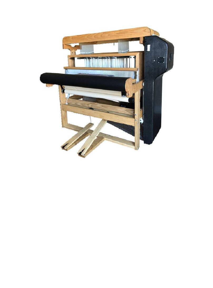
THE LOOM
On the next two pages are pictures of the full loom. Depending on the
options you have chosen, your loom may differ from the one shown here.

A-Series Dobby Loom Assembly Manual Introductory Information
the Loom Page | 9
Figure 1 - Full Loom - Left Side

Introductory Information A-Series Dobby Loom Assembly Manual
Page | 10 the Loom
Figure 2 - Full Loom - Right Side

A-Series Dobby Loom Assembly Manual Frame Assembly
Frame Assembly Page | 11
FRAME ASSEMBLY
FRAME ASSEMBLY

Frame Assembly A-Series Dobby Loom Assembly Manual
Page | 12 Loom Orientation
LOOM ORIENTATION
Before you get started, please take a minute to familiarize yourself with how
we describe the loom in this manual.
The front of the loom is where you will sit; the back of the loom is where the
warp beam is.
Everything is referenced as if you were sitting in the weaving position. The
right side of the loom is the side to your right as you are sitting at the loom
and the left side is to your left. A piece marked “bottom” would go toward
the floor.
On some drawings, we have included a “weaver symbol” to help clarify the
view of the drawing. This symbol shows a weaver seated at the weaving
bench. The symbol is included only to help clarify the orientation of the
drawing.
In this example, the weaver is sitting looking toward the right of the page.
That would indicate that the front of the loom is to the left of the page and
the rear of the loom to the right. If the arrow were pointing left, then the
rear of the loom is to the left.
The right and left of the dobby head is referenced as if you were standing
right in front of it.
TOOLS NEEDED FOR ASSEMBLY
There are a few tools you’ll need before we can get started. These are:
Philips head screwdriver
Light hammer
Pair of pliers
4" or 6" crescent wrench
Measuring Tape (for squaring the loom)
Small Level (for leveling the loom)
Scissors or Box cutter (for removing packing materials)
Ratchet/Socket set (optional)
Table of contents
Other AVL Looms Other manuals

AVL Looms
AVL Looms Compu-Dobby V User manual

AVL Looms
AVL Looms TECHNICAL EDUCATION LOOM User manual

AVL Looms
AVL Looms Jacq3G User manual

AVL Looms
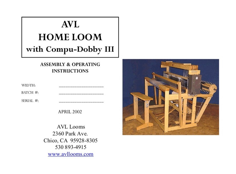
AVL Looms HOME LOOM with Compu-Dobby III Quick reference guide

AVL Looms
AVL Looms K Series User manual

AVL Looms
AVL Looms Rug Loom User manual

AVL Looms
AVL Looms Dobby User manual