CDVI DGLP60WLC User manual

The installer’s choice
cdvigroup.com
ENGLISH
EN
FRANCAIS
FR
DGLP60WLC
Hands-Free Proximity Card Reader - Wiegand
Lecteur Proximité Main Libre - Wiegand

2cdvigroup.com
EN
DGLP60WLC
Hands-Free Proximity Card Reader - Wiegand
INSTALLATION MANUAL
1] PRODUCT PRESENTATION
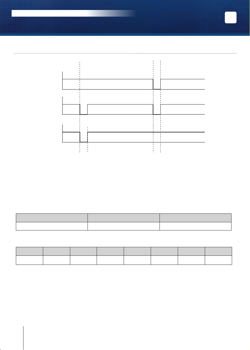
26, 30 or 44 bits Wiegand outputs.
Connection to the controller via
the Wiegand bus interface (INTBUSW).
Polycarbonate reader.
Surface mount.
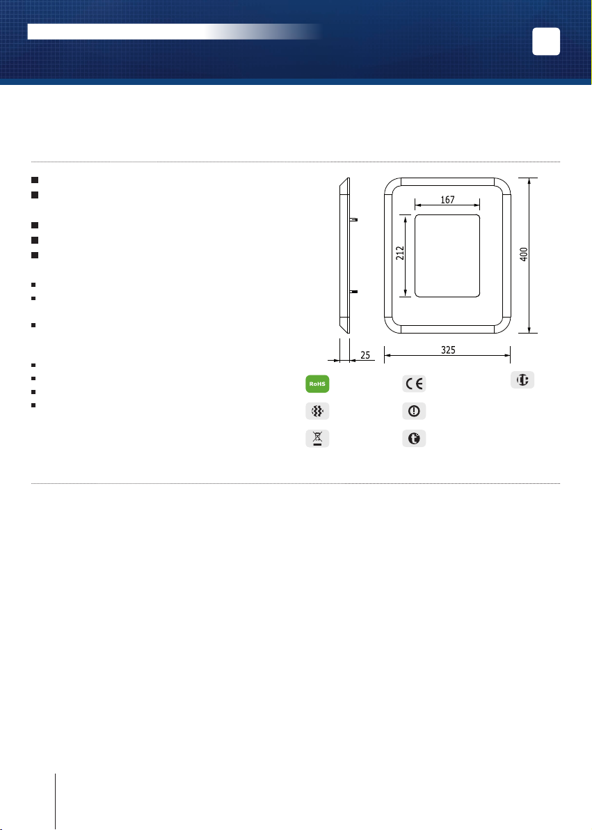
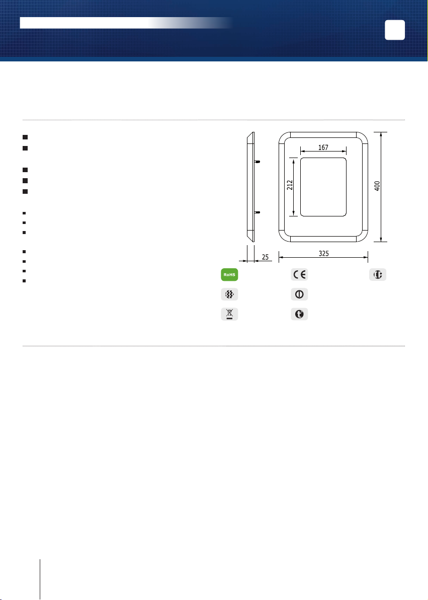
Reading distance from 30 to 60cm*.
Dimensions (L x W x D): 400 x 325 x 25mm.
Open collector outputs (Clock, Data 0 and Data 1).
Reading distance: up to 30cm with tags
(ref. PPC*) and up to 60cm with cards (ref. CPE*).
Self-contained electronics.
Audible and visual feedback.
Input voltage: 12V dc.
Consumption: 450mA.
Complies with European R&TTE directive 99/5/EC
and harmonised standards: ETS 301 489
and ETS 300-330-1-Ed 2001. Complies with applicable
EMC standards: EN 50133, EN 50130-4.
2] RECOMMENDATIONS
Installation recommendations
1.
To secure your installation, make sure
that the varistor is mounted in parallel
on the terminals of the lock with the power supply.
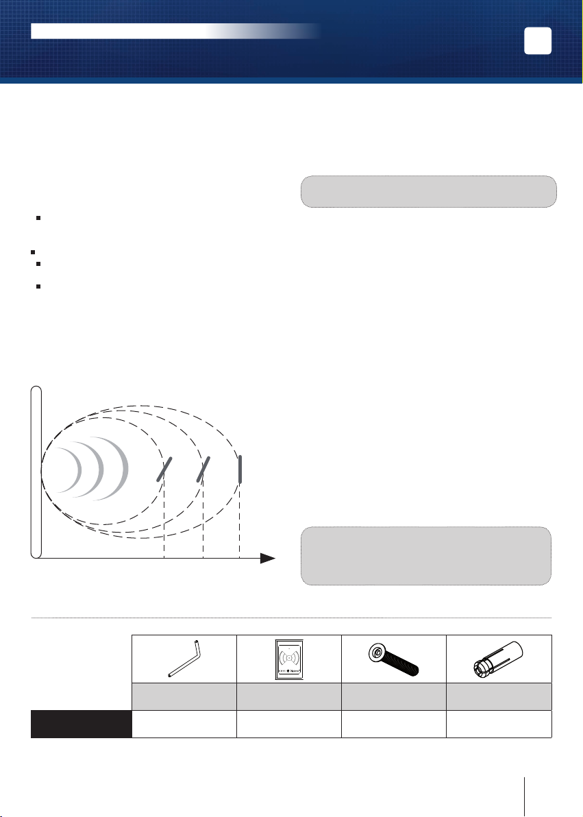
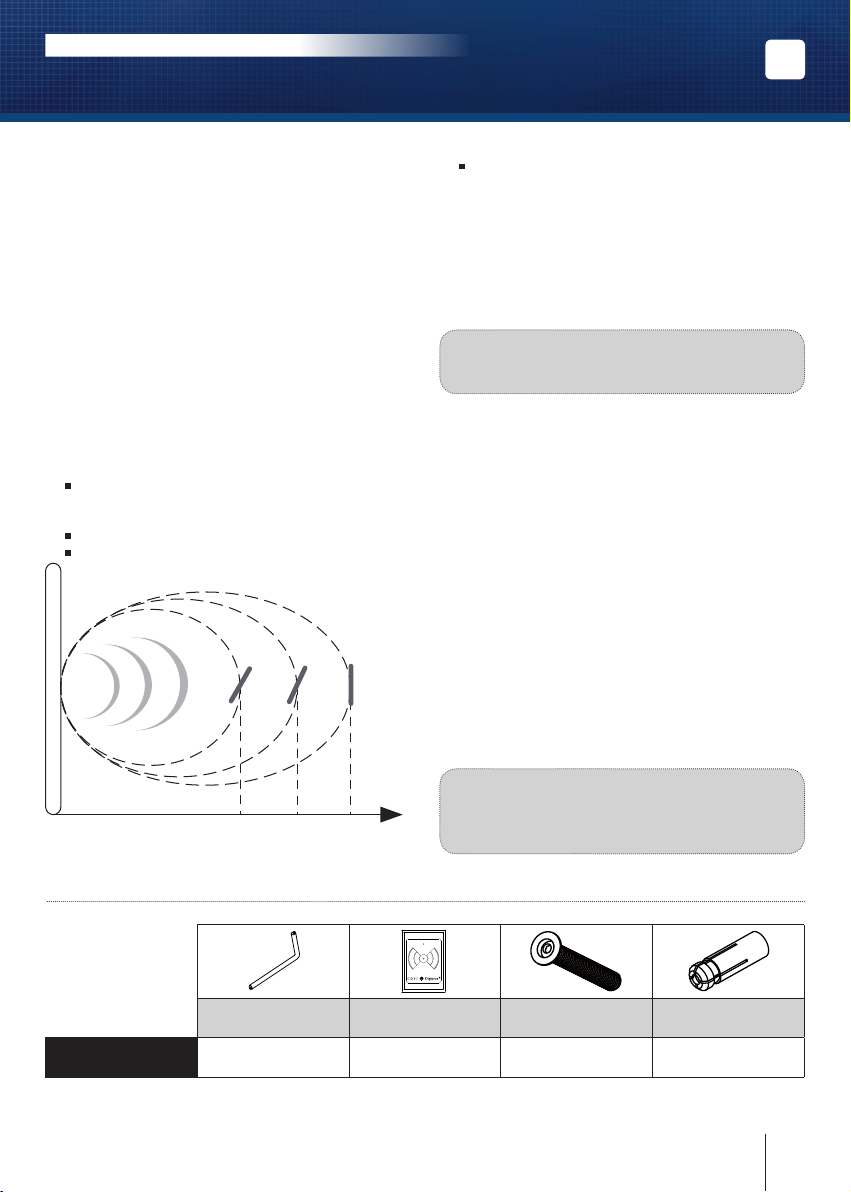
2.
Make sure that when mounting 2 Hands Free
readers, to keep a minimum distance between
the units to avoid reading the badges on both
readers simultaneously.
3.
When installing a reader near a loop conductor,
a conductor in the form of a close loop, a metal
plate then make sure to keep a cleared area
around
the reader of 1M on both sides and 1M at the back.
4. In some cases, put 0V to earth.
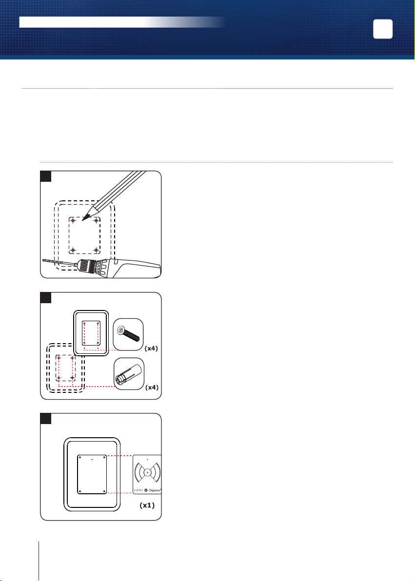
Mounting on a post
Avoid all conducting metals. Do not install
the reader in a closed conductor frame.
Recommended wiring
4 pairs 6/10th or AWG24 cable.
Environment
If you install these readers in a marine/salt
environment, we recommend spraying
a varnish coating on the terminal block
after wiring to prevent oxidation
.
Recommended power supplies
There are two suitable power supplies for these
Wiegand «proximity» readers: ARD12 and BS60.
Do not used switching power supply. These pro-
ducts must be powered in 12Vdc and the power
supply should be certied EN60950-1:2006/
A11:2009 standards and should be designed
to be a low power supply source.
Unfavourable situations
Avoid proximity to sources of electromagnetic
interference such as :
- IT transmission cables.
- Main power cables.
- Variators.
- Inverters.
- Computer monitors.
- Vehicle presence detection loop.
* This performance level is for an environment free from any electromagnetic disruptions.
IP53
-40°C to +70°C
CE certication
R&TTE certication
WEEE
Environmental
tests: vibrations
Thank you for buying our products and for the condence you placed
in our company.

3cdvigroup.com
EN
DGLP60WLC
Hands-Free Proximity Card Reader - Wiegand
INSTALLATION MANUAL
IP53
ODIAX®tools Sticker M5x42.5 DIAX®
screws M5 metal plugs
DGLP60 WLC
reader 1144
Orientation :
% distance :
30°
60% 25°
80% 0°
100%
Care : The more the badge is inclined
perpendicularly, the more the reading distance
will be reduced.
3] MOUNTING KIT
- Reinforced concrete walls.
- Any equipment not in conformity
with the EMC directive.
Optimisation
1.
When the reader is installed in a position that could
present one the previously mentioned unfavourable
situations, a few simple actions can sometimes
improve the performance of the reader:
Try to analyse the environment to attempt
to identify one of the possible sources
of interference (radiation, metal, etc).
Check the connections and the wiring.
Check the voltage on the power supply
and the voltage on the terminal block on the reader.
Test the reader in a different conguration
from the one initially intended:
- Move the reader.
- Change its orientation.
2.
If the reader works better in a different
conguration or position, it means
that the initial position is not optimal
and then should be changed until you nd
the best conguration.
Note : Test the card reader with a 12V
battery and proceed to the installation.
3
.
At start-up the DGLP60WLC reader perform an
auto calibration during 10 minutes to reach
optimal operation.
Using the badge
1.
Present the badge with its face towards
the reader approaching slowly until the reading
signal is obtained.
2. It is not necessary to shake the badge
in front of the reader.
3.
The badge should be presented
as parallel as possible to the reader
to optimize the reading distance.

1
2
3
*When installing the reader on a post refer to “recommendations” (P9).
Measure and mark the center lines to determine
the reader position. Drill the mounting screw holes
(Diametre: 4MM for the mounting plate and 6MM
for the reader). Drill the wiring access area.
Insert the brass anchors in the mounting holes, connect
the cable to the terminal block, Then mount the reader
with the DIAX®screws Leave an area to access the cable
complete the wiring). Make sure that the varistor is connected
on the lock (refer to page 2 «Recommendations»).
Place the sticker on the designated area
to hide the xing screws.
After checking that the mounting kit is complete, you can proceed with the nal installation
of your reader. Prepare the appropriate tools (Drill, screwdriver, measuring tape, etc)
and follow the mounting instructions
4 ] Mounting Instructions
Ref : DGLP60WLC*
4cdvigroup.com
EN
DGLP60WLC
Hands-Free Proximity Card Reader - Wiegand
INSTALLATION MANUAL

5cdvigroup.com
EN
DGLP60WLC
Hands-Free Proximity Card Reader - Wiegand
INSTALLATION MANUAL
ON ON
ON
Dip 3: Buzzer and LED
CDVI mode
- Standby, the LED and the buzzer
are both OFF.
(When a badge is presented
there is no feedback).
- Waiting for external commands
to activate the LED and the buzzer.
CENTAUR mode
- Standby, the LED and the buzzer
are both OFF.
(When a badge is presented
the LED light on orange for 150ms
and then turns red and the buzzer
is activated during 150ms.
- Waiting for external commands
to activate the LED and the buzzer.
Important : Dip 3 is set as soon as
power is applied.
Dip 4: Pull ups 12V or 5V
Open collector outputs:
Select the output voltage
according to the installation.
Dip 1 and 2:
Setting wiegand output
There are 3 types
of Wiegand output
:
- Wiegand 26-bit output
- Wiegand 30-bit output
- Wiegand 44-bit output
5] PRODUCT PRESENTATION
The hands free reader should not be installed on a metal surface. Use a separate power supply
for the DGLP60 WLC. Power the hands free reader before powering the controller.
44 Bit30 Bit26 Bit
DGLP60WLC
12V 5V
ON ON
ON
ON
DGLP60 WLC terminal blocks
Outputs Correspondence
+12V DC power supply
-0 V
HClock
D0 Data 0
D1 Data 1
BBuzzer
VGreen light
RRed light

6] OUTPUT FORMATS 26, 30 and 44 BITS WIEGAND
Chronograms
Open collector output with internal pulls up 1K at +5V or +12V according the ST4 position.
26-bits Wiegand Output
26-bits hexadecimal format.
1 - First parity: 1-bit – even parity for the rst 12-bits
Code of the badge: 6 last digits of the code.
Each byte is transferred from bit 7 to bit 0.
2 - 2nd parity: 1 bit – odd parity of the last 12 bits.
Bit 1 Bit 2 to bit 25 Bit 26
Even parity on bit 2 to bit 23 Data (24 bits)
Odd parity on bit 14 to bit 25
Example : code of the badge is 0108166A37.
1 0001 0110 0110 1010 0011 0111 0
Parity 1 1 6 6 A 3 7 Parity 2
The code transmitted is in hexadecimal format 166A37
Parity 1 : 0 if the number of 1 in bit 2 to bit 13 is even,
1 if the number of 1 in bit 2 to bit 13 is odd.
Parity 2 : 0 if the number of 1 in bit 14 to bit 25 is odd,
1 if the number 1 in bit 14 to bit 25 is even.
0 logic
\DATA1
\CLOCK
\DATA0
50 μs 50 μs
2ms 2ms
1 logic
6cdvigroup.com
EN
DGLP60WLC
Hands-Free Proximity Card Reader - Wiegand
INSTALLATION MANUAL

7cdvigroup.com
EN
DGLP60WLC
Hands-Free Proximity Card Reader - Wiegand
INSTALLATION MANUAL
30-bits Wiegand Output
30-bits hexadecimal format.
1 - First parity : 1 bit – even parity for the rst 14-bits.
Code : 7 last digits of the code.
2 - Second parity: 1 bit – odd parity for the last 14-bits.
Bit 1 Bit 2 to bit 29 Bit 30
Even Parity from bit 2 to bit 15 Data (28 bits) Odd Parity from bit 16 to bit 29
Example B : EM badge hexadecimal code: 0108166A37
1 1000 0001 0110 0110 1010 0011 0111 1
Parity 1 8 1 6 6 A 3 7 Parity 2
The code transmitted is in hexadecimal format 8166A37
Parity 1 : 0 if the number of 1 in bit 2 to bit 15 is even
1 if the number of 1 in bit 2 to bit 15 is odd
Parity 2 : 0 if the number of 1 in bit 16 to bit 29 is odd
1 if the number of 1 in bit 16 to bit 29 is even.
44-bits Wiegand Format Output
44-bits hexadecimal format.
1 - Data: 10 digit code number hexadecimal MSByte rst . Each hexadecimal digit = 4 bit, MSBit rst
2 - LRC : 4 bit = or restricted in between the digit of the data, MSBit rst.
Bit 1 to bit 40 Bit 41 to bit 44
Data MSBit rst LRC
Example A: EM badge hexadecimal code: 01001950C3.
0000 0001 0000 0000 0001 1001 0101 0000 1100 0011 0011
0100195 0 C 3 3
The code number of the card is: 01001950C3 in hexadecimal code.

1] PRESENTATION DES PRODUITS
Wiegand 26, 30 ou 44 bits.
Connexion à la centrale via
l’interface Bus Wiegand (INTBUSW).
Lecteur en polycarbonate.
Montage en applique.
Distance de lecture de 30 à 60 cm*.
Dimensions (L x l x P) : 400 x 325 x 25 mm.
Sorties en collecteur ouvert (Clock, Data 0
et Data 1).
Distance de lecture : jusqu’à 30 cm avec
badges (PPCG*) et jusqu’à 60 cm avec
cartes (CPE*).
Electronique intégrée.
Signalisation lumineuse et sonore.
Alimentation : 12 V DC.
Consommation : 450 mA.
Conforme à la directive européenne R&TTE 99/5/CE et selon les
normes harmonisées : ETS 301 489 et ETS 300-330-1-Ed 2001.
Conforme aux normes CEM appliquées : EN 50133, EN 50130-4.
2] RAPPELS ET RECOMMANDATIONS
Recommandations d’installation
1. Pour sécuriser l’installation, n’oubliez
pas de placer la varistance sur le système
de verrouillage en parallèle au niveau
de l’alimentation.
2.
La trop grande proximité de deux (ou plus)
lecteurs mains-libres provoquera un couplage
pouvant causer des lectures simultanées
sur plusieurs antennes,
ou conit des antennes.
3.
Installation du lecteur à proximité d’une boucle
conductrice fermée. Installation sur un support
métallique ou conducteur sous forme de boucle
fermée. Installation à proximité d’une masse
métallique conductrice :
dans ce cas de gure, respecter un écart
minimum de 1 m sur les cotés
et de 1 m à l’arrière.
4. Dans certains cas, mettre 0V à la terre.
Câble préconisés
Câble 4 paires 6/10ème.
Fixation sur pied
1. Eviter tout matériaux métallique conducteur.
2. Ne pas installer le lecteur dans un cadre
conducteur fermé.
Environnement
Si vous installez ces lecteurs dans un environ
nement marin/salin, il est préconisé de passer
du vernis en bombe sur les contacts après câblage
an de prévenir le risque d’oxydation.
Alimentations préconisées
Il existe deux alimentations adaptées pour ces
lecteurs «proximité» Wiegand : ARD12 et BS60.
Ne pas utiliser d’alimentation à découpage. Ces
produits doivent être alimentés en 12 V DC via une
alimentation conforme aux exigences de la norme
EN60950-1 :2006/A11 :2009 et construite pour
être une alimentation limitée en puissance.
8cdvigroup.com
IP53
-40°C à +70°C
Certication CE
Certication R&TTE
DEEE
Test vibrations
* Ces performances sont données pour un environnement exempt de toutes perturbations électromagnétiques.
Merci pour l’achat de ce produit et pour la conance que vous accordez
à notre entreprise.
FR
DGLP60WLC
Lecteur Proximité Main Libre - Wiegand
MANUEL D’INSTALLATION

3] KIT DE MONTAGE
9
cdvigroup.com
Outils ODIAX®Autocollant Vis DIAX® M5x42,5 Chevilles métal M5
Lecteur
DGLP60WLC 1144
Orientation :
% distance :
30°
60% 25°
80% 0°
100%
Attention : Plus le badge est incliné
perpendiculairement, plus la distance
de lecture sera réduite.
Cas défavorables
Eviter la proximité de sources de perturbations
électromagnétiques telles que :
- Câbles de transmission informatique.
-
Câbles de transport d’énergie.
- Variateurs.
- Ondulateurs.
- Ecrans informatiques.
- Boucle de détection de présence de véhicules.
- Murs en béton armé.
- Equipements en tous genre non conformes
au normes CEM.
Optimisation
1.
Lorsque le lecteur est installé dans un site
qui peut pésenter un cas défavorable cité
précédemment, certaines manipulations
simples peuvent parfois améliorer la situation:
Essayer d’analyser l’environnement pour tenter
de localiser une (des) sources de perturbations
éventuelles (rayonnements, métal...).
Vérier les connections et le câblage.
Vérier la tension d’alimentation
et le courant aux bornes du lecteur.
Tester le lecteur dans une conguration
différente de celle initialement prévue :
- Déplacer le lecteur.
- Changer son orientation.
2.
Si le lecteur fonctionne mieux
dans une conguration ou un emplacement
différent, cela signie que l’environnement
de la position initiale est défavorable,
et il est alors déconseillé de la conserver.
Note : Il est possible de tester le lecteur
sur batterie 12V an de pouvoir le déplacer
aisément.
3
.
Le lecteur atteind ses performances optimales
une dizaine de minutes environ après sa mise
en tension.
Utilisation du badge
1.
Présenter le badge face vers le lecteur
en approchant doucement jusqu’à obtenir
le signal de lecture.
2. Il n’est pas nécessaire d’agiter le badge
devant le lecteur.
3.
Le badge doit être présenté le plus parallèlement
possible au lecteur pour optimiser la distance
de lecture.
IP53
FR
DGLP60WLC
Lecteur Proximité Main Libre - Wiegand
MANUEL D’INSTALLATION

1
2
3
*Pour une xation sur pied voir rappel et recommandation (P9).
A l’aide du lecteur, prenez les marques pour xer le produit.
Percez 4 pts de xation pour vis DIAX® M5 sur le support
de montage au niveau des marques.
(Diamètres de perçage préconisés :
plaque de xation = 4 mm et lecteur = 6 mm).
Grâce à votre schéma de câblage, prévoyez la sortie
des câbles, cachés dans la surface ou à l’extérieur (moulure).
Placez les chevilles métal dans les trous, connectez les ls
aux borniers (voir schéma de câblage page 10), puis xez
le lecteur avec les quatre vis DIAX®grâce à l’outil DIAX®.
Positionner l’autocollant dans son logement pour cacher les vis.
Après avoir vérier que le kit de montage est complet, vous allez pouvoir
procéder à l’installation nale de votre lecteur. Réunissez le materiel approprié
(Perçeuse, tournevis, mètre,...) et suivez les recommandations de montage
qui correspondent au lecteur que vous allez installer.
4 ] Montage
Ref : DGLP60WLC*
10 cdvigroup.com
FR
DGLP60WLC
Lecteur Proximité Main Libre - Wiegand
MANUEL D’INSTALLATION

ON
DGLP60 WLC Bornier 8 points
Bornier Correspondance
+Alimentation 12 V DC
-0 V
HClock
D0 Data 0
D1 Data 1
BBuzzer
VVoyant vert
RVoyant rouge
44 Bit30 Bit26 Bit
DGLP60 WLC
Dip 3 : Buzzer et LED
Mode CDVI
- Au repos, le voyant est éteint
et le buzzer est sur OFF.
(Lors de la présentation
d’un badge il n’y à pas d’action).
- Attente des commandes venant
de l’extérieur pour le voyant
et le buzzer.
Mode CENTAUR
- Au repos, le voyant est éteint
et le buzzer est sur OFF.
(Lors de la présentation d’un badge
le voyant est orange durant 150 ms
puis revient rouge et le buzzer
est sur ON pendant 150 ms.
- Attente des commandes venant
de l’exterieur pour le voyant et le
buzzer.
Important : Le Dip 3 est pris en
compte, à la mise sous tension .
Dip 4 : Pulls up 12 V ou 5V
Pour les sorties à collecteur ou-
vert, il y a deux niveaux
de sorties possibles :
Ce strap permet à l’utilisateur
de choisir la tension de sortie
en fonction de l’installation.
Dip 1 et 2 :
Sélection de sortie Wiegand
Il y a 3 types de sorties Wiegand
:
- Sortie Wiegand 26 bit
- Sortie Wiegand 30 bit
- Sortie Wiegand 44 bit
12V 5V
ON ON
ON ON
ON
ON
5] PRESENTATION DES PRODUITS
Le lecteur de proximité main libre ne doit pas être, ni placée
ni xée sur une surface métallique. [Si la centrale de gestion
possède un système de proximité (avec une antenne), la distance
entre l’antenne DGLP60WLC et la centrale doit être supérieure
à 5 m].
La centrale et l’antenne doivent être alimentées séparément.
Il est imperatif d’alimenter la centrale avant l’antenne.
ON ON
11cdvigroup.com
FR
DGLP60WLC
Lecteur Proximité Main Libre - Wiegand
MANUEL D’INSTALLATION

6] FORMAT DE SORTIE WIEGAND 26, 30 ET 44 BITS
Chronogrammes
Format Wiegand 26 bits
Format 26 bits hexadécimal.
1 - 1ère parité : 1 bit – parité paire des 12 premiers bits
Code du badge : 6 derniers termes.
Chaque mot est transmis bit de poids fort en premier.
2 - 2ème parité: 1 bit – parité impaire des 12 derniers bits
Bit 1 Bit 2 à bit 25 Bit 26
Parité paire sur bit 2 à bit 23 Donnée (24 bits)
Parité impaire sur bit 14 à bit 25
Exemple : pour un badge dont le code hexadécimal est 0108166A37.
1 0001 0110 0110 1010 0011 0111 0
Parité 1 1 6 6 A 3 7 Parité 2
Le code émis est 166A37 en hexadécimal
Parité 1 : 0 si le nombre de 1 dans bit 2 à bit 13 est paire,
1 si le nombre de 1 dans bit 2 à bit 13 est impaire.
Parité 2 : 0 si le nombre de 1 dans bit 14 à bit 25 est impaire,
1 si le nombre de 1 dans bit 14 à bit 25 est paire.
0 logique
\DATA1
\CLOCK
\DATA0
50 μs 50 μs
2ms 2ms
1 logique
12 cdvigroup.com
FR
DGLP60WLC
Lecteur Proximité Main Libre - Wiegand
MANUEL D’INSTALLATION

Format Wiegand 30 bits
Format 30 bits hexadécimal.
1 - 1ère parité : 1 bit – parité paire des 14 premiers bits.
Code du badge : 7 derniers termes.
Chaque mot est transmis bit de poids fort en premier.
2 - 2ème parité: 1 bit – parité impaire des 14 derniers bits.
Bit 1 Bit 2 à bit 29 Bit 30
Parité paire sur bit 2 à bit 15 Donnée (28 bits) Parité impaire sur bit 16 à bit 29
Exemple B : pour un badge ayant le code hexa : 0108166A37
1 1000 0001 0110 0110 1010 0011 0111 1
Parité 1 8 1 6 6 A 3 7 Parité 2
Le code émis est 8166A37 en hexadécimal
Parité 1 : 0 si le nombre de 1 dans bit 2 à bit 15 est paire
1 si le nombre de 1 dans bit 2 à bit 15 est impaire
Parité 2 : 0 si le nombre de 1 dans bit 16 à bit 29 est impaire
1 si le nombre de 1 dans bit 16 à bit 29 est paire
Format Wiegand 44 bits
Format 44 bit hexadécimal.
Données : 10 chiffres hexadécimaux (octet de poids fort en premier),
Chaque chiffre hexadécimal = 4 bit (bit de poids fort en premier).
LRC : 4 bit = OU exclusif entre les chiffres de la donnée (bit de poids fort en premier).
Bit 1 à bit 40 Bit 41 à bit 44
Code du badge LRC
Exemple A : pour un badge ayant le code hexa : 01001950C3.
0000 0001 0000 0000 0001 1001 0101 0000 1100 0011 0011
0100195 0 C 3 3
Le code émis est : 01001950C3 en hexadécimal.
13cdvigroup.com
FR
DGLP60WLC
Lecteur Proximité Main Libre - Wiegand
MANUEL D’INSTALLATION

7] NOTES
14 cdvigroup.com
FR
DGLP60WLC
Lecteur Proximité Main Libre - Wiegand
MANUEL D’INSTALLATION

15cdvigroup.com
FR
DGLP60WLC
Lecteur Proximité Main Libre - Wiegand
MANUEL D’INSTALLATION

The installer’s choice
cdvigroup.com
Reference : G0301FR0321V06
Extranet : EXE-CDVI_IM DGLP60 WLC CMYK A5 EN-FR 06
All the information contained within this document (pictures, drawing, features, specications and dimensions)
could be perceptibly different and can be changed without prior notice.
Toutes les informations mentionnées à titre indicatif sur le présent document (photos, dessins, caractéristiques
techniques et dimensions) peuvent varier et sont susceptibles de modications sans notication préalable.
*G0301FR0321V06*
CDVI Group
FRANCE (Headquarter/Siège social)
Phone: +33 (0)1 48 91 01 02
Fax: +33 (0)1 48 91 21 21
CDVI
FRANCE + EXPORT
Phone: +33 (0)1 48 91 01 02
Fax: +33 (0)1 48 91 21 21
CDVI AMERICAS
[CANADA - USA]
Phone: +1 (450) 682 7945
Fax: +1 (450) 682 9590
CDVI
BENELUX
[BELGIUM - NETHERLAND - LUXEMBOURG]
Phone: +32 (0) 56 73 93 00
Fax: +32 (0) 56 73 93 05
CDVI
TAIWAN
Phone: +886 (0)42471 2188
Fax: +886 (0)42471 2131
CDVI
SUISSE
Phone: +41 (0)21 882 18 41
Fax: +41 (0)21 882 18 42
CDVI
CHINA
Phone: +86 (0)10 62414516
Fax: +86 (0)10 62414519
CDVI
IBÉRICA
[SPAIN - PORTUGAL]
Phone: +34 (0)935 390 966
Fax: +34 (0)935 390 970
CDVI
ITALIA
Phone: +39 0321 90 573
Fax: +39 335 127 89 96
CDVI
MAROC
Phone: +212 (0)5 22 48 09 40
Fax: +212 (0)5 22 48 34 69
CDVI
SWEDEN
[SWEDEN - DENMARK - NORWAY - FINLAND]
Phone: +46 (0)31 760 19 30
Fax: +46 (0)31 748 09 30
CDVI
UK
[UNITED KINGDOM - IRELAND]
Phone: +44 (0)1628 531300
Fax: +44 (0)1628 531003
CDVI DIGIT
FRANCE
Phone: +33 (0)1 41 71 06 85
Fax: +33 (0)1 41 71 06 86
Table of contents
Languages:
Other CDVI Card Reader manuals

CDVI
CDVI U4Go Series User manual

CDVI
CDVI KRYPTO K1BT Instruction Manual

CDVI
CDVI MOONARW User manual

CDVI
CDVI DGLPTWLC User manual

CDVI
CDVI NANOPB Instruction Manual

CDVI
CDVI DGLPM WLC User manual

CDVI
CDVI STAR1M User manual

CDVI
CDVI DGLPWLC User manual

CDVI
CDVI Mifare SOLARMW User manual

CDVI
CDVI SOLARPW User manual

CDVI
CDVI SOLARPW User manual

CDVI
CDVI DGLPWLC User manual

CDVI
CDVI KRYPTO K2 Instruction Manual

CDVI
CDVI DGLIMWLC User manual

CDVI
CDVI U4GO A6U48 User manual

CDVI
CDVI DGLPM WLC User manual

CDVI
CDVI DGLP FN WLC 26 User manual

CDVI
CDVI DESFire EV2 Instruction Manual

CDVI
CDVI KRYPTO K2I User manual

CDVI
CDVI Mifare Desfire EV1 User manual