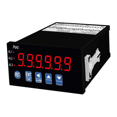
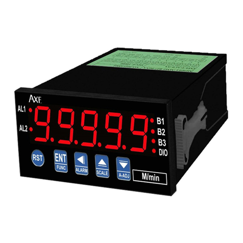
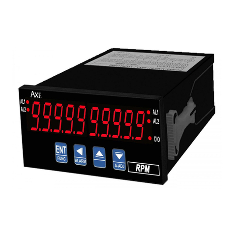
AXE MRT Series User manual

AL1
AL2
DIO
ROOT
AXE Microprocess Rate & Totalizer Controller Meter
MRT series
■FEATRUES
◎
Accept DC/mA,DC/A,DC/mV,AC/A input signal,finish
totalize and cont ol function ◎
15BIT DAC analog output can be modified, 0~10V
/4~20mA by inside switch jumpe
◎
Accu acy 0.1% F.S.±1 digit ◎Display ave age can be modified(1~99)
◎
Rate display ange 0 to 19999 can be modified
◎
Totalize display ange 0 to 999999999 ◎
BAUD RATE:19200/9600/4800/2400
◎
0.4
”
highlight display
◎
Rate and Totalize decimal point can be modified
◎
Man-machine inte face,easy to ope ate
◎
Totalize timebase can be modified(1/60/3600sec)
◎
EEPROM Saving ,data safekeeping about 10 yea s
◎
Scale can be modified(0.00001 to 9999.99999) ◎
Modified inside pa amete ,must have pass code
◎
Totalize ove automatic eset ◎
Dual ala m function
◎
Totalize can be stop count by te minal ◎
Powe down saving
◎
Math- ootext acto function ◎
Exciting supply DC24V,<25mA
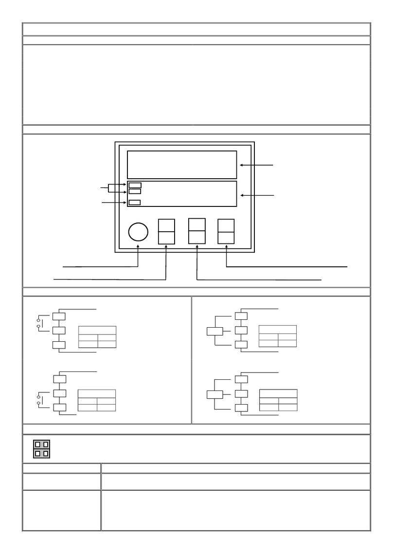
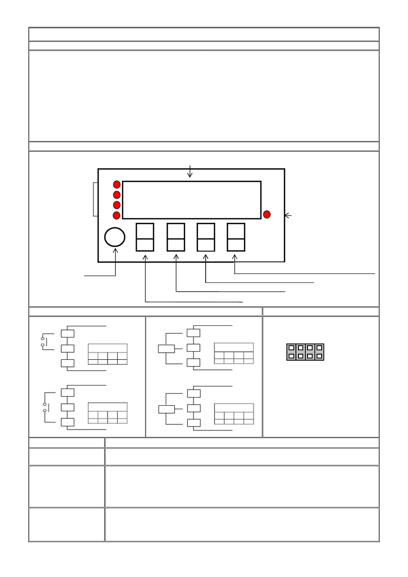
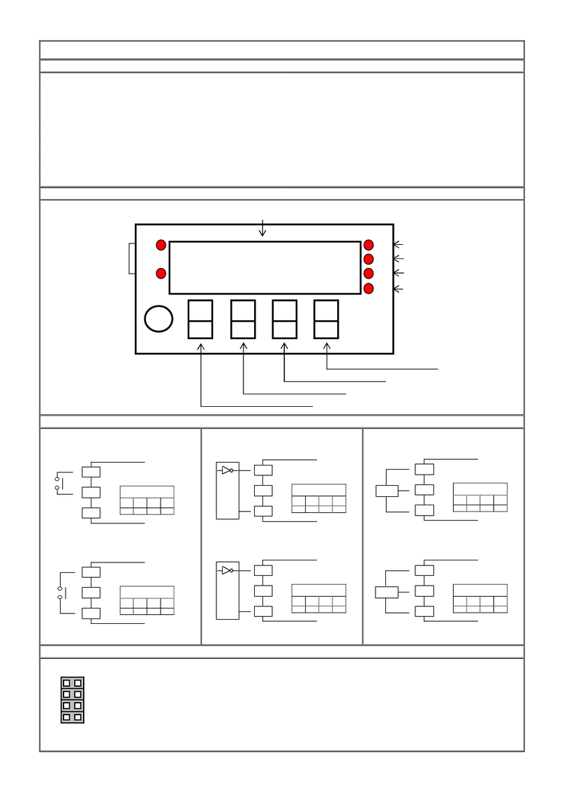
■Name of Pa ts
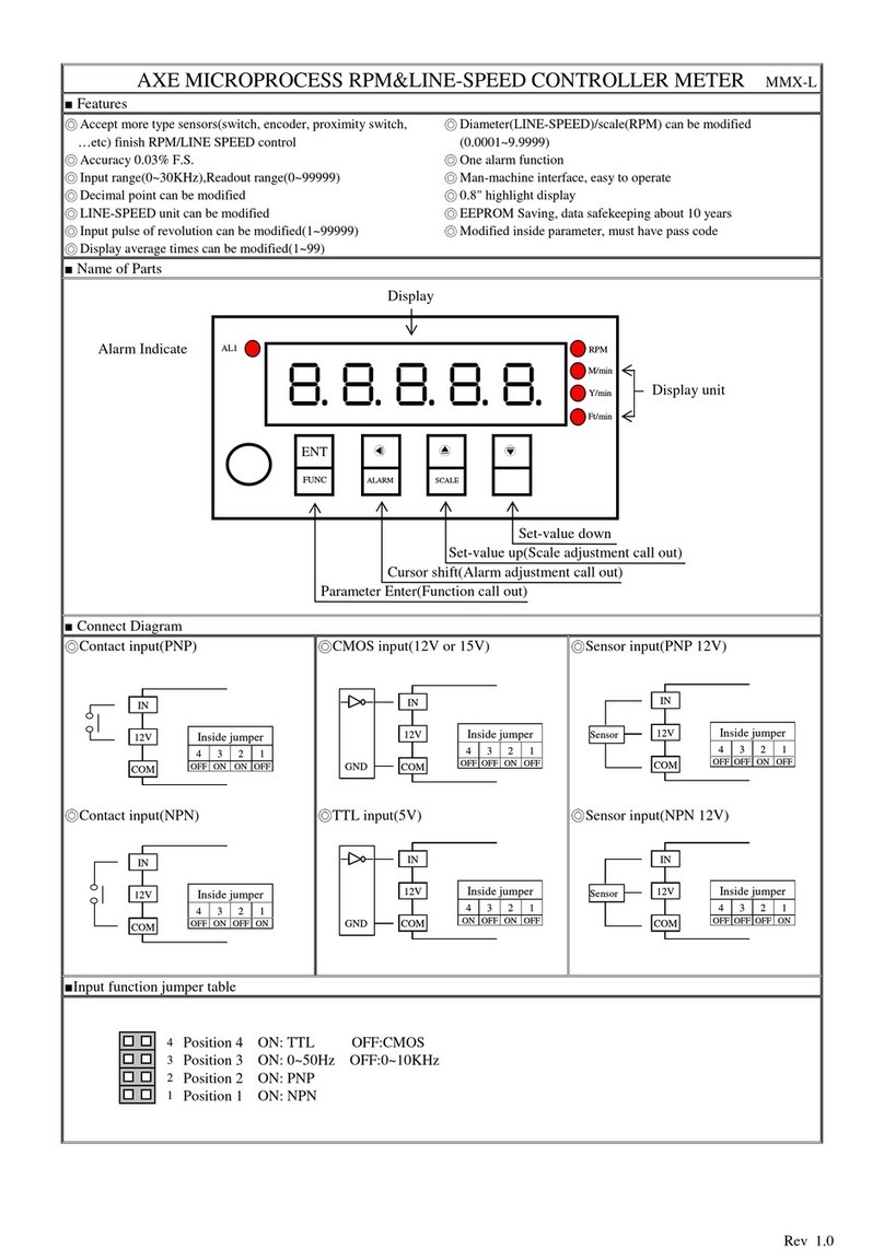
■Ala m action mode & Connect Diag am Desc iption
1. ACT=HI,Display value≧Alarm value,Relay active,Display value<Alarm value,Relay reset
2. ACT=LO,Display value<Alarm value,Relay active,Display value≧Alarm value,Relay reset
3. R T Connect terminal function:When terminal R T&COM short about 200ms,Totalizer reset
4.
GATE Connect terminal function:When terminal GATE&COM short about 200ms,Totalizer
stop count
5. ROOT Connect terminal function:When terminal ROOT&COM short about 200ms,Input
Rootextractor action
■Analog output function jumpe table
Position 1&3 ON: DC 4~20 mA OUTPUT
Position 2&4 ON: DC 0~10V OUTPUT
Alarm indicate
Totalizer Display
Parameter ENTER(Function call out)
Set-value up(Rate display adjustment call out)
Set-value Down(Analog output adjustment call out)
Cursor shift(Alarm adjustment call out)
Totalizer Reset
Communication indicate
ENT
FUNC
E
ALARM
D-ADJ
A-ADJ
RST
Rate display
Rootextractor indicate
4 3 2 1

Key introduce Operation Manual
key function 1.In normal display,The key function is call out setting group
2.In parameter setting page,The key function is data ENTER,and goto next page
key function 1.In normal display,The key function is call out alarm value setting page
2.Into parameter setting page,the parameter mark&data
is alternate display,If need modify data can
press shift key into setting procedure,The display is lock parameter data,this time must let off key
about 0.2 sec ,press again,the cursor (twinkle express)is cycle moving left.(Key response about 0.2
sec.)
key function 1. In normal display,The key function is call out adjustment rate display page (DZERO&DSPAN)
2.Into parameter setting page,the parameter mark&data is alternate display,If need modify data can
press up key into setting procedure,The display is lock parameter data,this time must let off key
about 0.2 sec ,press again,the parameter data will increment .(Key response about 0.2 sec.)
key function 2. In normal display,The key function is call out adjustment analog output page(AZERO&ASPAN)
2.Into parameter setting page,the parameter mark&data is alternate display,If need modify data can
press down key into setting procedure,The display is lock parameter data,this time must let off key
about 0.2 sec ,press again,the parameter data will decrement .(Key response about 0.2 sec.)
&
key function In setting group or setting page press
&
key return normal display,but if in setting page the
modify data will be lost
No key in anything In setting group or setting page no key in anything about 2 minutes,return normal display,but if in
setting page the modify data will be lost
Step
Parameter Mark Description
Parameter Mark
Operation Manual
1
Normal display
Press
/FUNC key into P.COD setting page
2
P.COD(Pass Code input
page)
1.Key in 5 digit pass code with
&
&
key
2.Press
key,the pass code is right into setting group,otherwise
return normal display
SYS(System setting group)
ROP(Alarm setting group)
AOP(Analog output setting
group)
DOP(Communication setting
group)
1.Select setting group with
key
2.Press
key into setting page of selection setting group
3
SYS(System setting group)
Press
key decide SYS setting group,press
key into DPR setting
page
3-1
DPR(Decimal Point Rate
setting page)Default=0
1.Decide rate decimal point position with
&
key(0 to 4)
2.Press
key enter data and into DSPH setting page
3-2
DSPH(Display High Scale
setting page)Default=19999
1.Decide rate display high scale with
&
&
key(0 to 19999)
2.Press
key enter data and into AVG setting page
3-3
AVG (Dispaly Average time
setting page)Default=1
1.Decide display average times with
&
&
key(1 to 99)
2.Press
key enter data and into LCUT setting page
3-4
LCUT (Low Cut)
Default=0
1. Decide display low cut with
&
&
key (0~99)
2. Press
key enter data and into C.TIME setting page
3-5
DPT (Decimal Point
Totalizer
setting page
)Default=0
1.Decide totalizer decimal point position with
&
key(0 to 8)
2.Press
key enter data and into C.TIME setting page
3-6
C.TIME (Count Time)
Default=1
1.Decide C.TIME with
&
key(1/60/3600 sec)
2.Press
key enter data and into SCALE setting page
3-7
SCALE (Scale to totalize
setting page)Default=1
1.Decide Totalize scale with
&
&
key(0.00001 to 9999.99999)
2.Press
key enter data and into CODE setting page
3-8
CODE(Pass Code setting
page)Default=0
1.Decide pass code with
&
&
key(0 to 19999)
2.Press
key enter data and into LOCK setting page
3-9
LOCK(Panel Lock setting
page)Default=NO
1.Decide panel lock with
&
key(NO or YES)
2.Press
key enter data and return SYS setting group

4
ROP(Alarm setting group)
Press
key decide ROP setting group,press
key into AL.SEL
setting page
4-1
AL.SEL(Alarm Select setting
page )Default=RATE
1.Decide Alarm select with
&
key(RATE or TOTALIZER)
2.Press
key enter data and into ACT1 setting page
4-2
ACT1(Alarm Active 1 setting
page )Default=HI
1.Decide Alarm active 1 with
&
key(HI or LO)
2.Press
key enter data and into ACT2 setting page
4-3
ACT2(Alarm Active 2 setting
page)Default=HI
1.Decide Alarm active 2 with
&
key(HI or LO)
2.Press
key enter data and into DEL1 setting page
4-4
DEL1(Alarm Delay 1 setting
page)Default=0
1.Decide Alarm delay 1with
&
&
key(0~99 sec)
2.Press
key enter data and into DEL2 setting page
4-5
DEL2(Alarm Delay 2 setting
page)Default=0
1.Decide Alarm delay 2 with
&
&
key(0~99 sec)
2.Press
key enter data and return ROP setting group
5
AOP(Analog output setting
group)
Press
key decide AOP setting group,press
key into AO.SEL
setting page
5-1
AO.SEL(
Analog Output
Select
setting page
)Default=RATE
1.Decide Analog output select with
&
key
(RATE or TOTALIZER)
2.Press
key enter data and into ANLO setting page
5-2
ANLO(A/O Zero According
to Display setting page)
Default=0
1.Decide ANLO with
&
&
key (0~999999999)
2.Press
key enter data and into ANHI setting page
5-3
ANHI(A/O Span According
to Display setting page)
Default=19999
1.Decide ANHI with
&
&
key(0~999999999)
2.Press
key enter data and return AOP setting group
6
DOP(Communication setting
group)
Press
key decide DOP setting group,press
key into ADDR
setting page
6-1
ADDR(Communication --
Address setting page )
Default=0
1.Decide Communication address with
&
&
key(0~255)
2.Press
key enter data and into BAUD setting page
6-2
BAUD(Communication Baud
Rate setting page)
Default=19200
1.Decide baud rate with
&
key(19200,9600,4800,2400)
2.Press
key enter data and into PARI setting page
6-3
PARI(Communication Parity
Check setting page)
Default=n82
1.Decide parity check with
&
key(n82,n81,even,odd)
2.Press
key enter data and return DOP setting group
Step
Parameter Mark Description
Parameter Mark
Operation Manual
7
Normal display
Press
key about 3 sec.,into AL1 setting page
7-1
AL1 (Alarm value 1 setting
page)
Default=0
1.Decide Alarm value 1 with
&
&
key(0 to 999999999)
2.Press
key enter data and into AL2 setting page
7-2
AL2 (Alarm value 2 setting
page)
Default=0
1.Decide Alarm value 2 with
&
&
key(0 to 999999999)
2.Press
key enter data and return normal display
Step
Parameter Mark Description
Parameter Mark
Operation Manual
8
Normal display
Press
key about 3 sec.,into DZERO adjustment page
8-1
DZERO(Rate Display Zero
Adjustment page)
Default=0
1.Input low signal,and adjustment display zero with
&
key
2.Press
key enter data and into DSPAN adjustment page
8-2
DSPAN(Rate Display Span
Adjustment page)
Default=0
1.Input high signal,and adjustment display span with
&
key
2.Press
key enter data and return normal display

Step
Parameter Mark Description
Parameter Mark
Operation Manual
9
Normal display
Press
key about 3 sec.,into AZERO adjustment page
9-1
AZERO(Analog Output
Zero Adjustment page)
Default=0
1.Adjustment analog output zero with
&
&
key(
±
9999)
2.Press
key enter data and into ASPAN adjustment page
9-2
ASPAN(Analog Output
Span Adjustment page)
Default=0
1.Adjustment analog output span with
&
&
key(
±
9999)
2.Press
key enter data and return normal display
Appendix
Error Mark Description
Error Mark Analyze & Description
1
Input over error detect
Input signal ove ange(120%)
2
Display over error detect
Display ove ange(19999)
3
A/D Converter error detect
1.
Input signal ove ange(180%)
2.
Inside ci cuit damage
Please moving input signal if still display ADER,please
contact us
4
EEPROM error detect
1.Exte nal inte fe ence when EEPROM ead/w ite
2.EEPROM w ite ove 100 million times(gua antee 10 yea s)
Please powe eset,if still display E-00,doing
following
step:
1.
E-00 & No alte nate display fo inqui e eset EEPROM
2.
Decide Yes with
o
key,p ess
key etu n no mal
display
3.EEPROM was eset,Please follow step 1~10 set again

MRT Modbus RTU Mode Protocol Address Map
DATA Format 16Bit/32Bit,sign bit
8000~7FFF( –32768~32767 )/80000000~7FFFFFFF(-2147483648~2147483647)
Address
Name Description Accept
0000 DPR Input range 0000~0004(0~4)0:10
0
,1:10
-1
,~,4:10
-4
R/W
0002 D PH Input range 0000~4E1F(0~19999) R/W
0004 AVG Input range 0001~0063(1~99) R/W
0006 DPT Input range 0000~0004(0~8)0:10
0
,1:10
-1
,~,8:10
-8
R/W
0008 CTIME Input range 0000~0002(0~2)0:1,1:60,2:3600 sec R/W
000A LCUT Input range 0000~0063(0~99) R/W
000C LOCK Input range 0000~0001(0~1)0:NO,1:YE R/W
000E AL EL Input range 0000~0001(0~1)0:RATE,1:TOTAL R/W
0010 ACT1 Input range 0000~0001(0~1)0:HI,1:LO R/W
0012 ACT2 Input range 0000~0001(0~1)0:HI,1:LO R/W
0014 DEL1 Input range 0000~0063(0~99) R/W
0016 DEL2 Input range 0000~0063(0~99) R/W
0018 AO EL Input range 0000~0001(0~1)0:RATE,1:TOTAL R/W
001A ADDR Input range 0000~00FF(0~255) R/W
001C BAUD Input range 0000~0003(0~3)0:19200,1:9600,2:4800,3:2400 R/W
001E PARI Input range 0000~0003(0~3)0:N82,1:N81,2:EVEN,3:ODD R/W
0020 AZERO Input range D8F1~270F(-9999~9999) R/W
0022 A PAN Input range D8F1~270F(-9999~9999) R/W
0024 ANLO Input range 00000000~3B9AC9FF(0~999999999) R/W
0028 ANHI Input range 00000000~3B9AC9FF(0~999999999) R/W
002C AL1 Input range 0~3B9AC9FF(0~999999999) R/W
0030 AL2 Input range 0~3B9AC9FF(0~999999999) R/W
0034 CALE Input range 1~3B9AC9FF(1~999999999) R/W
0040 TOTAL Display range 00000000~3B9AC9FF(0~999999999) R
0044 RATE Display range 0000~4E1F(0~19999) R
Other AXE Measuring Instrument manuals

AXE
AXE MCH Series User manual

AXE
AXE MFRTS Series User manual

AXE
AXE MC48 Series User manual

AXE
AXE MMRD-M Series User manual

AXE
AXE MM2 Series User manual

AXE
AXE MMR Series User manual

AXE
AXE MMRD Series User manual

AXE
AXE MMRH Series User manual

AXE
AXE MMR-N Series User manual

AXE
AXE MMC Series User manual