manuals.online logo
Brands
  1. Home
  2. •
  3. Brands
  4. •
  5. AXE
  6. •
  7. Measuring Instrument
  8. •
  9. AXE MM2 Series User manual

AXE MM2 Series User manual

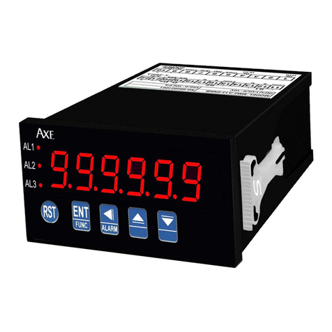
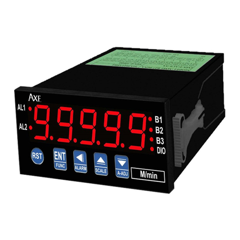
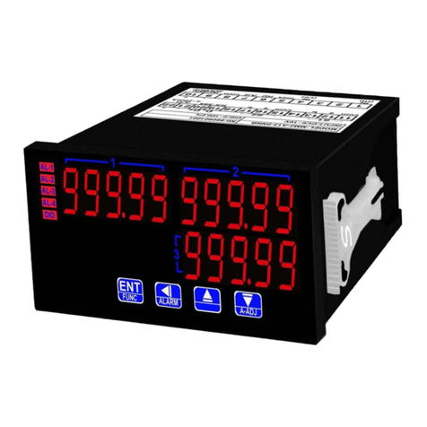
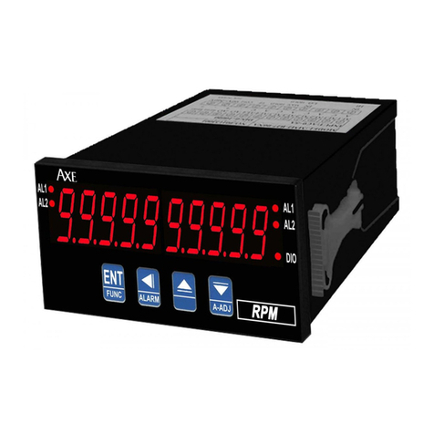
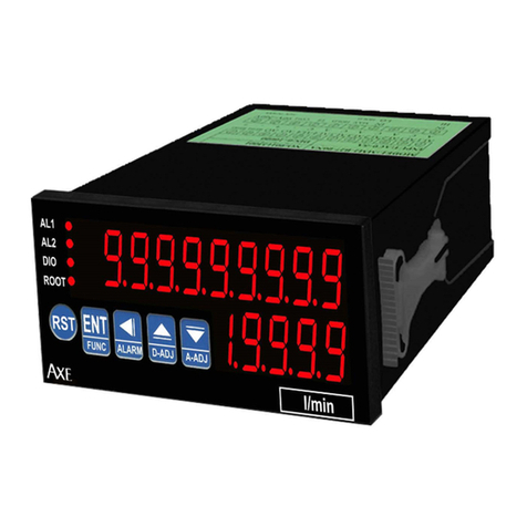
AXE MICROPROCESS PANEL CONTROLLER METER
MM2 Series
■Features
◎Measuring DCA/DCV/ACA/ACV/Potentiometer/Pt-
100/
Transmitter/Load Cell/ esistor
…
.etc ◎Display average can be modified(1~99)
◎15BIT DAC analog output
◎
Accuracy 0.1% F.S.±1 digit ◎
RS485communication interface,Photocol MODBUS RTU MODE
◎
Display range -19999~19999 can be modified ◎
BAUD ATE:19200/9600/4800/2400
◎
Decimal point can be modified ◎
0.56
”
highlight display
◎
Display value can Auto-zero and Hold function ◎
Man-machine interface ,easy to operate
◎
Display value can Max. hold function ◎
EEP OM Saving,data safekeeping about 10 years
◎
4 Alarm function ◎
Modified inside parameter,must have pass code
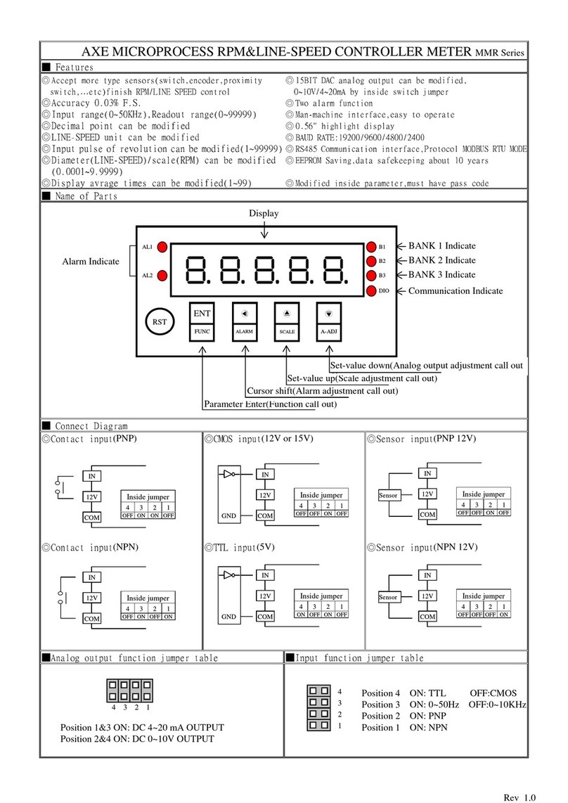
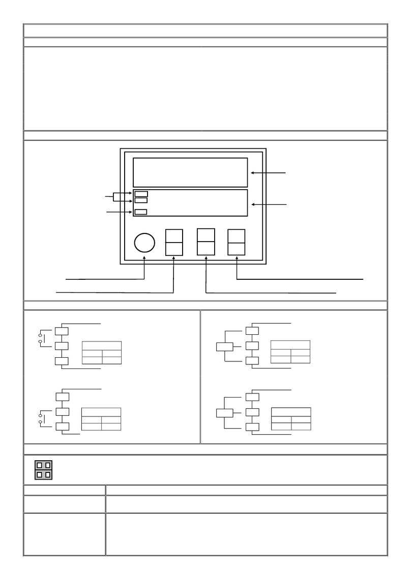
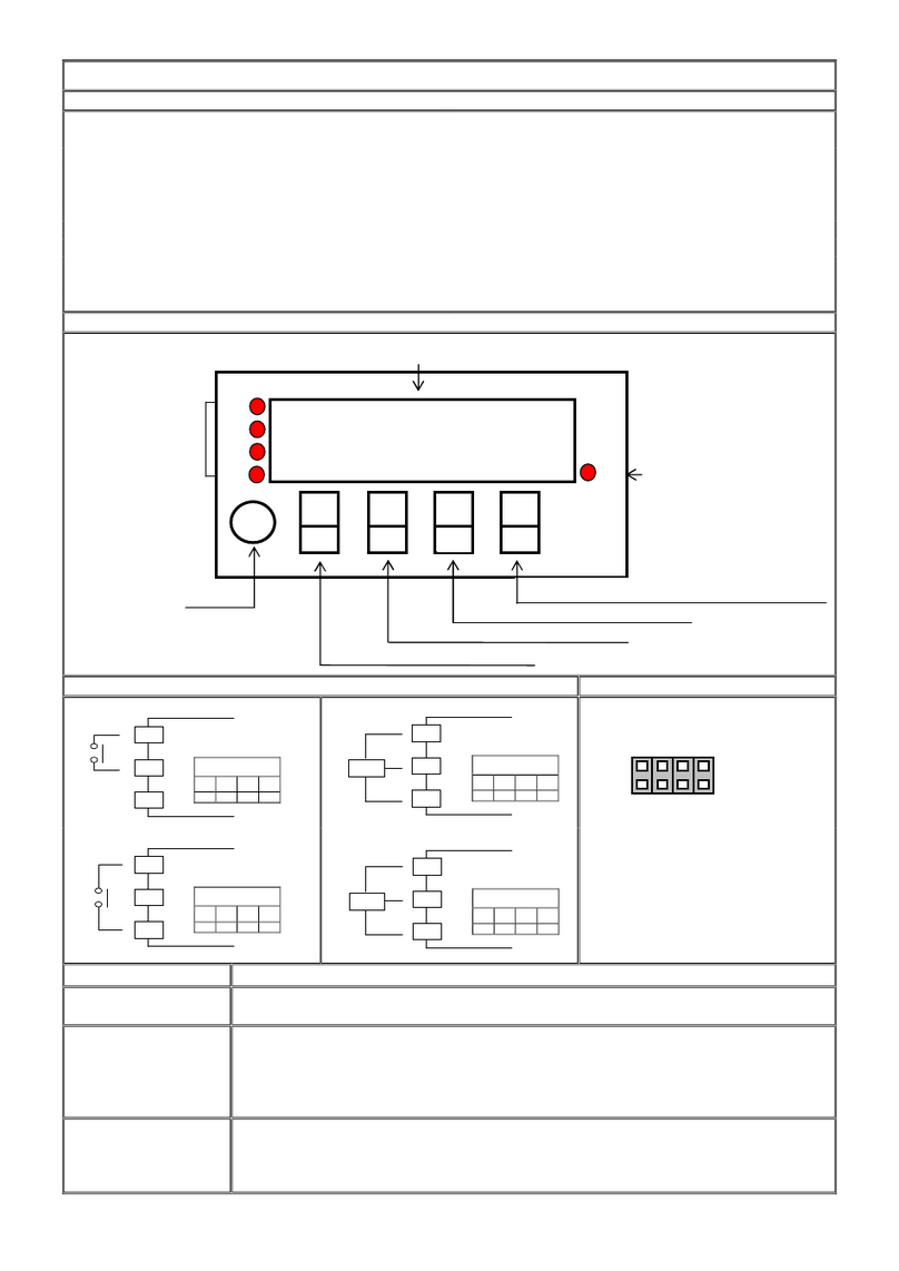
■Name Of Parts
■Alarm Function Diagram
◎
ACT=HI
˙Indication≧setting
(alarm lamp and relay on)
˙Indication<setting
(alarm lamp and relay off)
◎
ACT=LO
Indication<setting
(alarm lamp and relay on)
˙Indication≧setting
(alarm lamp and relay off)
■Analog Output Function Jumper Table
Position 1&3 ON: DC 4~20 mA OUTPUT
Position 2&4 ON: DC 0~10V OUTPUT
Alarm indicate
燈

AL1
AL2
AL3
AL4
AZ
HD
MAX
DIO
Display
Auto-zero indicate
Parameter ENTER(Function call out)
Set
-
valu
e up
(
Display adjustment call out
)
Set
-
value down
(
Analog output adjustment call out
)
Cursor shift(Alarm adjustment call out)
Auto-zero Function

ENT
FUNC

E
ALARM

D-ADJ

A-ADJ
Display HOLD indicate
Display Max. hold indicate
保持指示燈
Communication indicate
INPUT
HI set value
Lo set value
Hysteresis
(ACT=HI)
Hysteresis
(ACT=Lo)
HI
C
omparative
output
Lo comparative
output
’
(
-
+tart band)
-start band
Input= ero
-
input limit
Lo
relay
output
’
(-start band)
+start band
Symmetrical
+start
band
Decided of DEL and SDT
Not active range
Not active range
ON
OFF
4 3 2 1
All manuals and user guides at all-guides.com
Key Introduce Operation Manual

Key Function 1.In normal display,The key function is call out setting group
2.In parameter setting page,The key function is data Enter , and goto next page

Key Function 1.In normal display,The key function is call out alarm value setting page
2.Into parameter setting page,the parameter mark&data is alternate display,If need modify data can
press shift key into setting procedure,The display is lock parameter data,this time must let off key
about 0.2 sec,press again,the cursor(twinkle express)is cycle moving left.
(Key Response about 0.2
sec)

Key Function 1.In normal display,The key function is call out adjustment display value (DZERO&DSPAN)page
2.Into parameter setting page,the parameter mark&data is alternate display,If need modify data can
press up key into setting procedure,The display is lock parameter data,this time must let off key
about 0.2 sec,press again,the parameter data will increment. (Key Response about 0.2 sec)

Key Function 1.In normal display,The key function is call out adjustment analog output (AZERO&ASPAN)page
2.Into par
ameter setting page,the parameter mark&data is alternate display,If need modify data can
press down key into setting procedure,The display is lock parameter data,this time must let off key
about 0.2 sec,press again the parameter data will decrement. (Key Response about 0.2 sec)

&

Key Function In setting group or setting page press

&

key return normal display,but if in setting page the
modify data will be lost
No Key in anything In setting group or setting page no key in anything about 2 minutes,return normal display
Step Parameter Mark Description
Parameter Mark
Operation Manual
1 Normal display

Press

/FUNC key into P.COD setting page

2 P.COD(Pass code input
page)

1.Key in 5 digit pass code with

or

or

key
2.Press

key,the pass code is right into setting grou
p ,
otherwise
return normal display
3 SYS(System setting group)

OP(Alarm setting group)

AOP(Analog output setting
group)

DOP(Communication
setting group)

1.
Select setting group with

key
2.
Press

key into setting page of selection setting group
4 SYS(System setting group)

Press

key decide SYS setting group , press

key into
DP setting page

4-1
DP(Decimal Point)
Default=0

1.Decide decimal point position with

or

key (0 to 4)
2.Press

key enter data and into DSPL setting page

4-2
DSPL(Display Low Scale)
Default=0

1.Decide display low scale with

&

&

key (-19999~19999)
2.Press

key enter data and into DSPH setting page

4-3
DSPH(Display High Scale)
Default=19999

1.Decide display high scale with

&

&

key (-19999~19999)
2.Press

key enter data and into AVG setting page

4-4
AVG (Average)
Default=1

1.Decide display Average times with

&

&

key (1~99)
2.Press

key enter data and into LCUT setting page

4-5
LCUT (Low Cut)
Default=0

1.Decide display low cut with

&

&

key (0~99)
2.Press

key enter data and into CODE setting page

4-6
CODE(Pass Code)
Default=0

1.Decide Pass code with

&

&

key (0~19999)
2.Press

key enter data and into LOCK setting page

4-7
LOCK(Panel Lock)
Default=NO

1.Decide panel lock with

or

key (NO or YES)
2.Press

key enter data and return SYS setting group
5 OP(Alarm setting group)

Press

key decide OP setting group,press

key into
ACT1 setting page

5-1
ACT1(Alarm Active 1
setting page )Default=HI

1.Decide active 1 with

or

key(HI or LO)
2.Press

key enter data and into ACT2 setting page

5-2
ACT2(Alarm Active 2
setting page )Default=HI

1.Decide active 2 with

or

key(HI or LO)
2.Press

key enter data and into ACT3 setting page
All manuals and user guides at all-guides.com

5-3
ACT1(Alarm Active 3
setting page )Default=HI

1.Decide active 3 with

or

key(HI or LO)
2.Press

key enter data and into ACT4 setting page

5-4
ACT2(Alarm Active 4
setting page )Default=HI

1.Decide active 4 with

or

key(HI or LO)
2.Press

key enter data and into HYS1 setting page

5-5
HYS1(Alarm Hysteresis 1
setting page)Default=0

1.Decide Hysteresis 1 with

or

or

key(0~999)
2.Press

key enter data and into HYS2 setting page

5-6
HYS2(Alarm Hysteresis 2
setting page)Default=0

1.Decide Hysteresis 2 with

or

or

key(0~999)
2.Press

key enter data and into HYS3 setting page

5-7
HYS3(Alarm Hysteresis 3
setting page)Default=0

1.Decide Hysteresis 3 with

or

or

key(0~999)
2.Press

key enter data and into HYS4 setting page

5-8
HYS4(Alarm Hysteresis 4
setting page)Default=0

1.Decide Hysteresis 4 with

or

or

key(0~999)
2.Press

key enter data and into DEL1 setting page

5-9
DEL1(Alarm Delay 1
setting page)Default=0

1.Decide delay 1 with

or

or

key(0~99.9 sec)
2.Press

key enter data and into DEL2 setting page

5-10
DEL2(Alarm Delay 2
setting page)Default=0

1.Decide delay 2 with

or

or

key(0~99.9sec)
2.Press

key enter data and into DEL3 setting page

5-11
DEL3(Alarm Delay 3
setting page)Default=0

1.Decide delay 3 with

or

or

key(0~99.9 sec)
2.Press

key enter data and into DEL4 setting page

5-12
DEL4(Alarm Delay 4
setting page)Default=0

1.Decide delay 4 with

or

or

key(0~99.9sec)
2.Press

key enter data and into SB setting page

5-13
SB(Start band)
Default=0

1.Decide start band with

or

or

key(-999~999)
2.Press

key enter data and into SDT setting page

5-14
SDT(Start Delay Time)
Default=0

1.Decide start delay time with

or

or

key(0~99.9sec)
2.Press

key enter data and return OP setting group
6
AOP(Analog output setting
group)

Press

key decide AOP setting group , press

key into
ANLO setting page

6-1
ANLO(A/O Zero According
to Display setting
page)Default=0

1.Decide ANLO with

or

or

key(-19999~19999)
2.Press

key enter data and into ANHI setting page

6-2
ANHI(A/ O Span According
to Display setting
page)Default=0

1.Decide ANHI with

or

or

key(-19999~19999)
2.Press

key enter data and return AOP setting group
7 DOP(Communication
setting group)

press

key decide DOP setting group,press

key into
ADD setting page

7-1
ADD (Communication
–
Addr
ess setting page )
Default=0

1.Decide address with

or

or

key(0~255)
2.Press

key enter data and into BAUD setting page

7-2
BAUD(Communication Baud
ate setting page)Value
on Default=19200

1.Decide baud rate with

or

key(19200,9600,4800,2400)
2.Press

key enter data and into PA I setting page

7-3
PA I(Communication
Parity Check setting
page)Default=n82

1.Decide parity check with

or

key(n82,n81,even,odd)
2.Press

key enter data and return DOP setting group
Step Parameter mark description Parameter mark
Operation manual
8 Normal display

Press

/ALA M key about 3 sec,into AL1 setting page

8-1
AL1 (Alarm value 1 setting
page) Default=0

1.Decide alarm value 1 with

or

or

key(-19999~19999)
2.Press

key enter data and into AL2 setting page

8-2
AL2 (Ala
rm value 2 setting
page) Default=0

1.Decide alarm value 2 with

or

or

key(-19999~19999)
2.Press

key enter data and into AL3 setting page

8-3
AL3 (Alarm value 3 setting
page) Default=0

1.Decide alarm value 3 with

or

or

key(-19999~19999)
2.Press

key enter data and into AL4 setting page

8-4
AL4 (Alarm value 4 setting
page) Default=0

1.Decide alarm value 4 with

or

or

key(-19999~19999)
2.Press

key enter data and return normal display
All manuals and user guides at all-guides.com
Step Parameter mark description Parameter mark
Operation manual
9 Normal display

Press

/A-ADJkey about 3 sec,into DZE O adjustment page

9-1
DZE O(Display Zero Adjust
)Default=0

1.Adjustment display zero with

or

key
2.Press

key enter data and into DSPAN adjustment page

9-2
DSPAN(Display Span Adjust
)Default=0

1.Adjustment display span with

or

key
2.Press

key enter data and return normal display
Step Parameter mark description Parameter mark
Operation manual
10 Normal display

Press

/A-ADJkey about 3 sec,into AZE O adjustment page

10-1
AZE O(Analog Output
Zero Adjustment page)
Value on EEP OM reset=0

1.Adjustment analog output zero with

or

or

key(±9999)
2.Press

key enter data and into ASPAN adjustment page

10-2
ASPAN(Analog Output
Span Adjustment page)
Value on EEP OM reset=0

1.Adjustment analog output span with

or

or

key(±9999)
2.Press

key enter data and return normal display
Appendix
Error Mark Description
Error Mark Analyze & Description
1 Input over error detect

Input signal over range(120%)
2 Input under error detect

Input signal under range(-20%)
3
Display o er error detect

Display over range(19999)
4
Display under error detect

Display under range(-19999)
5 A/D Converter error
detect

1.
Input signal over range (180%)
2.
Inside circuit damage
Please moving input signal if still display ADE ,please
contact us


6 EEP OM error detect

1.External interference when EEP OM read/write
2.EEP OM write over 100 million times(guarantee 10 years)
Please power reset,if still display E-
00,doing following
step:
1.
E-00 & No alternate display for inquire reset EEP OM
2.
Decide Yes with

or

key,press

key return normal
display
3.EEP OM was reset,Please follow step 1~10 set again
All manuals and user guides at all-guides.com
MM2 Modbus RTU Mode Protocol Address Map
Data format 16/32Bit,sign bit 8000~7FFF(
–
32768~32767)/80000000~7FFFFFFF(-2147483648~2147483647)
Address
Name Description Accept
0000 DP DP,range 0000~0004(0~4)0:10
0
,1:10
-1
,2:10
-2
,3:10
-3
,4:10
-4
/W
0002 DSPL DSPL,range B1E1~4E1F(-19999~19999) /W
0004 DSPH DSPH,range B1E1~4E1F(-19999~19999) /W
0006 AVG AVG,range 0001~0063(1~99) /W
0008 LCUT LCUT,range 0000~0063(0~99) /W
000A CODE CODE,range 0000~4E1F(0~19999) /W
000C HYS1 HYS1,range 0000~03E7(0~999) /W
000E HYS2 HYS2,range 0000~03E7(0~999) /W
0010 HYS3 HYS3,range 0000~03E7(0~999) /W
0012 HYS4 HYS4,range 0000~03E7(0~999) /W
0014 DEL1 DEL1,range 0000~03E7(0~999) /W
0016 DEL2 DEL2,range 0000~03E7(0~999) /W
0018 DEL3 DEL3,range 0000~03E7(0~999) /W
001A DEL4 DEL4,range 0000~03E7(0~999) /W
001C SB SB,range FC19~03E7(-999~999) /W
001E SDT SDT,range 0000~03E7(0~999) /W
0020 AL1 AL1,range B1E1~4E1F(-19999~19999) /W
0022 AL2 AL2,range B1E1~4E1F(-19999~19999) /W
0024 AL3 AL3,range B1E1~4E1F(-19999~19999) /W
0026 AL4 AL4,range B1E1~4E1F(-19999~19999) /W
0028 ANLO ANLO,range B1E1~4E1F(-19999~19999) /W
002A ANHI ANHI,range B1E1~4E1F(-19999~19999) /W
002C AZE O AZE O,range D8F1~270F(-9999~9999) /W
002E ASPAN ASPAN,range D8F1~270F(-9999~9999) /W
0030 ADD ADD ,range 0000~00FF(0~255) /W
0032 BAUD BAUD,range 0000~0003(0~3)0:19200,1:9600,2:4800,3:2400 /W
0034 PA I PA I,range 0000~0003(0~3)0:N.8.2.,1:N.8.1.,2:EVEN,3:ODD /W
003E ACT ACT,BIT0:ACT1,BIT1:ACT2,BIT2:ACT3,BIT3:ACT4(0:HI,1:LO) /W
0040 STATUS STATUS Bit0:LOCK,Bit1:AZ,Bit2:HOLD,Bit3:MAX 0:Disable 1:Enable
0042 AZ AZ VALUE,range B1E1~4E1F(-19999~19999)
0044 HOLD HOLD VALUE,range B1E1~4E1F(-19999~19999)
0046 MAX MAX. VALUE,range B1E1~4E1F(-19999~19999)
0048 DISPLAY
DISPLAY,range B1E1~4E1F(-19999~19999)
All manuals and user guides at all-guides.com

Other AXE Measuring Instrument manuals

AXE MMR-N Series User manual

AXE

AXE MMR-N Series User manual

AXE MMC Series User manual

AXE

AXE MMC Series User manual

AXE MCH Series User manual

AXE

AXE MCH Series User manual

AXE MMX-L User manual

AXE

AXE MMX-L User manual

AXE MFRTS Series User manual

AXE

AXE MFRTS Series User manual

AXE MCHH Series User manual

AXE

AXE MCHH Series User manual

AXE MC48 Series User manual

AXE

AXE MC48 Series User manual

AXE MRT Series User manual

AXE

AXE MRT Series User manual

AXE MMRD-M Series User manual

AXE

AXE MMRD-M Series User manual

AXE MM2 Series User manual

AXE

AXE MM2 Series User manual

AXE MMRH Series User manual

AXE

AXE MMRH Series User manual

AXE MMR Series User manual

AXE

AXE MMR Series User manual

AXE MMRD Series User manual

AXE

AXE MMRD Series User manual

Popular Measuring Instrument manuals by other brands

Opti-Logic XT Series manual

Opti-Logic

Opti-Logic XT Series manual

ALS SEC2020 user guide

ALS

ALS SEC2020 user guide

MATLAB SigDigger user manual

MATLAB

MATLAB SigDigger user manual

Agilent Technologies M9302A Service guide

Agilent Technologies

Agilent Technologies M9302A Service guide

Energenie ENER007 user guide

Energenie

Energenie ENER007 user guide

Siemens SICAM Q100 7KG95 Series manual

Siemens

Siemens SICAM Q100 7KG95 Series manual

IFM Electronic efector300 SD6101 operating instructions

IFM Electronic

IFM Electronic efector300 SD6101 operating instructions

Blizzard Pocket Rocket II quick start guide

Blizzard

Blizzard Pocket Rocket II quick start guide

Siemens SITRANS F MAG 6000 I operating instructions

Siemens

Siemens SITRANS F MAG 6000 I operating instructions

Martel PTC8010 Reference manual

Martel

Martel PTC8010 Reference manual

E+E Elektronik OMNIPORT 20 manual

E+E Elektronik

E+E Elektronik OMNIPORT 20 manual

socomec DIRIS A20 operating instructions

socomec

socomec DIRIS A20 operating instructions

SONBEST SL5090B user manual

SONBEST

SONBEST SL5090B user manual

Bushnell TOUR V4 SHIFT manual

Bushnell

Bushnell TOUR V4 SHIFT manual

Burkert 8026 quick start

Burkert

Burkert 8026 quick start

id LAB FOTOMETER 2008 COOL user guide

id LAB

id LAB FOTOMETER 2008 COOL user guide

Spartan Power SP-PM120 user manual

Spartan Power

Spartan Power SP-PM120 user manual

Haug Static Control Digital Operating	 instruction

Haug

Haug Static Control Digital Operating instruction

manuals.online logo
manuals.online logoBrands
  • About & Mission
  • Contact us
  • Privacy Policy
  • Terms and Conditions

Copyright 2025 Manuals.Online. All Rights Reserved.