iv
Table of Contents
Disclaimers.....................................................................................................ii
ESD Precautions...........................................................................................iii
Chapter 1 Introduction............................................. 1
1.1 Features...............................................................................................1
1.2 Specifications......................................................................................2
1.3 Utilities Supported ..............................................................................3
Chapter 2 Module and Pin Assignments.................. 5
2.1 Module Dimensions and Fixing Holes...............................................5
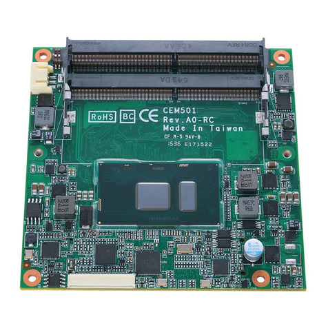
2.2 Module Layout.....................................................................................7
2.3 Jumper Settings..................................................................................8
2.3.1 Clear CMOS (JP1) ...................................................................................... 8
2.3.2 Auto Power on (JP2)................................................................................... 8
2.4 Connectors..........................................................................................9
2.4.1 Ethernet Port (LAN1)................................................................................... 9
2.4.2 M.2 B Key 2242 Socket (CN2).................................................................. 10
2.4.3 M.2 M Key 2280 Socket (CN3) ..................................................................11
2.4.4 USB 3.1 Gen1 Port Stacks (CN4 and CN5).............................................. 12
2.4.5 Audio Jack Mic-in Connector (CN6).......................................................... 12
2.4.6 Audio Jack Line-out Connector (CN7) ...................................................... 13
2.4.7 Reset button (CN8) ................................................................................... 13
2.4.8 HDMI Connector (eDP) (CN9) .................................................................. 13
2.4.9 Power State indicator LED (D25)................................................................ 13
2.4.10 M.2 E KEY Connector (NGFF1)................................................................ 14
2.4.11 Power On/Off button (SW1)...................................................................... 14
2.4.12 SDM Edge Connector (J1)........................................................................ 15
Chapter 3 Hardware Description ........................... 17
3.1 Microprocessor .................................................................................17
3.2 BIOS ...................................................................................................17
3.3 System Memory.................................................................................17
3.4 I/O Port Address Map........................................................................18
3.5 Interrupt Controller (IRQ) Map .........................................................19
3.6 Memory Map ......................................................................................24
