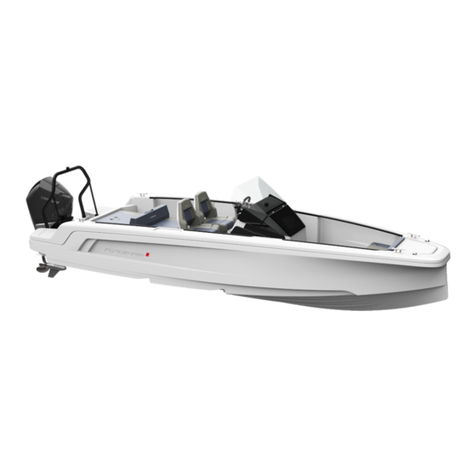
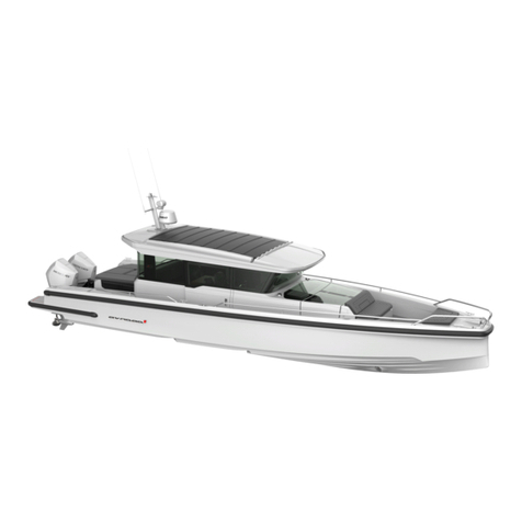
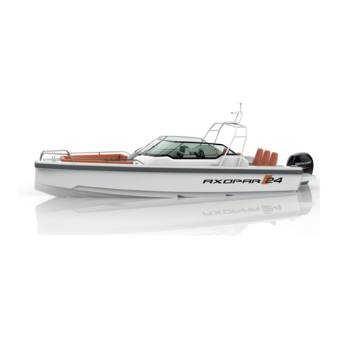
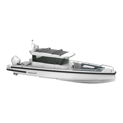
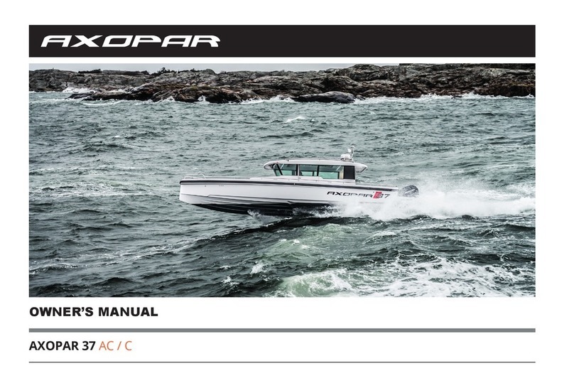
Axopar 28 OPEN User manual

USER’S MANUAL
AXOPAR 28 OPEN / OC / T-TOP


FOREWORD ..................................................................................... 2
INTRODUCTION ............................................................................... 4
Symbols used ................................................................................... 4
Identification .................................................................................... 5
Manufacturer’s plate......................................................................... 5
General layout Cabin ........................................................................ 6
Work decks and swim ladders Cabin ................................................ 7
General layout AC ........................................................................... 8
Work decks and swim ladders AC .................................................... 9
Technical data ................................................................................ 10
Declaration of conformity .............................................................. 11
Toilet-, black water- and grey water systems ................................... 12
Electrical system ............................................................................. 14
Bilge pump system ......................................................................... 16
Deck and security equipment ......................................................... 17
Fire control and fuel-,
cooling-, and gas systems .............................................................. 18
LPG equipment .............................................................................. 20
Installation of LPG equipment ........................................................ 21
Steering system .............................................................................. 22
Environment .................................................................................. 23
CONTENTS
HANDLING OF THE BOAT ............................................................... 24
Starting the engine ........................................................................ 24
Before weighing anchor ................................................................. 24
Leaving the jetty ............................................................................ 25
Stability and buoyancy ................................................................... 25
Driving the boat ............................................................................. 25
Dead man’s switch ......................................................................... 26
Driving at high speed ..................................................................... 26
Using the trim tabs ........................................................................ 27
Driving in rough seas ..................................................................... 28
Manoeuvring in narrow channels ................................................... 28
Docking ......................................................................................... 28
Before anchoring ........................................................................... 29
Anchoring, mooring and towing .................................................... 29
AFTER RUNNING THE ENGINE(S) .................................................... 30
Maintenance .................................................................................. 30
Wooden interior ............................................................................ 30
Cover ............................................................................................. 31
Preventing frost damage ................................................................ 31
Lifting and transporting ................................................................. 32
Actions before winter storage ......................................................... 33
Action before launching ................................................................. 33
APPENDIXES ................................................................................. 34
1

In this user’s manual you will find important information that will help
you handle and maintain your boat in a safe and easy manner. Further-
more, the manual contains detailed information about the boat and
the systems installed, and general information about handling and tak-
ing care of your boat.
We advise you to read the manual carefully and familiarise yourself with
your boat before you start to use it. Naturally this owner’s manual is not
a substitute for boating safety skills or good seamanship. If this is your
first boat or if this boat type is new to you, we ask for your own com-
fort and safety that you ensure you can handle the boat before you set
out for the first time. Your boat dealer, local boat clubs and national
motorboat or yacht federations will gladly inform you about local sea
schools or recommend approved instructors.
You should ensure that the anticipated wind and wave conditions cor-
respond to the design category of your boat, and that you and your
crew are able to handle the craft in these conditions. Design category
C corresponds to wind and wave conditions that can vary from storm
to strong winds. Category C also indicates a risk of exceptional swell
and gust. Even if your boat is designed for such conditions, they are still
very dangerous. Only a capable, fit and trained crew, using a well main-
Congratulations on your new Axopar boat! We thank you for
choosing this boat and wish you safe and enjoyable moments out
on the waters.
FOREWORD
tained craft, can satisfactorily operate in such conditions.
This owner’s manual is not a detailed maintenance or troubleshooting
guide. If problems occur, you should contact the boat manufacturer or
their representative. When you are in need of maintenance or repair
and alteration work, you should always turn to competent and trained
workshops. Changes that can affect the boat’s security features must be
assessed, carried out and documented by competent professionals. The
boat manufacturer cannot be held responsible for unauthorised modifi-
cations. Every change to the boat’s centre of gravity (from highly mount-
ed heavy equipment or a new engine type etc.) will significantly affect
the stability, trim and performance of the boat.
The boat owner must take local and international regulations into con-
sideration concerning the boat crew, equipment and handling of the
boat. In some countries, a driving licence or a separate authorization is
required for driving the boat and in some countries special regulations
might also be in force.
Always maintain your craft properly and make allowance for the deteri-
oration that will occur over time and as a result of heavy use or misuse
of the craft. Any craft, no matter how strong it may be, can be severe-
2

ly damaged if not used properly. Inappropriate use of this boat i.e. use
which is not compatible with safe boating, is not allowed. It is always
important to adjust the speed and direction of the craft to the sea con-
ditions and your own boating experience.
If your boat is fitted with a life raft, carefully read its operating manu-
al. On-board, the craft should have the appropriate safety equipment
according to the type of craft, weather conditions, etc. This equipment
is compulsory in some countries. The crew should be familiar with the
use of all safety equipment and the most important actions in different
emergency situations (man overboard recovery, towing, etc.). Sailing
schools and clubs regularly organize rescue drills.
The equipment in your boat may differ from the equipment used in the
pictures and illustrations in this manual. The reason for this might be
e.g. due to any optional equipment you have chosen or modifications
that have been adapted since this manual was made. In such cases we
recommend that you contact your local dealer for additional informa-
tion regarding the equipment in question.
Keep this manual in a safe place and pass it on to the new owner if
you sell your boat. If the manual is mislaid or destroyed, a copy can be
ordered from your dealer. The warranty on the engine, as well as option-
al equipment such as trim tabs, bow thrusters, navigation equipment
and other equipment fitted afterwards, is on the individual supplier’s
conditions. The warranties for this equipment and the suppliers’ contact
information are enclosed. Concerning all other warranty claims, please
contact you Axopar dealer mentioned on the cover page.
See the purchase agreement/order for the scope of your purchase. In
case something does not work satisfactorily with your boat or its equip-
ment, you can check the service documents for possible service and
repair measures. In the event of uncertainty, you should always con-
tact your dealer.
Please note that your boat is a recreational craft, thus not suitable for
professional use.
Specifications, illustrations and examples and related constructional data
in this publication are not binding. We reserve the rights for changes.
3

INTRODUCTION
SYMBOLS USED IN THIS MANUAL:
The purpose of the owner’s manual is not to be a complete ser-
vice guide or repair handbook, but to guide the owner into the
characteristics of his/her new boat and to handle it in a prop-
er way.
CE-CATEGORY – C
This boat belongs to category C. The CE-categories means that boats in
each category must be designed and constructed to withstand the fol-
lowing parameters in respect of stability, buoyancy, and other relevant
essential requirements stated. One requirement is that the boats must
be easy to manoeuvre.
A. Ocean
These boats are designed for extended voyages, where conditions expe-
rienced may exceed wind force 8 Beaufort Scale and include significant
wave heights of at least 4 metres. Under such conditions these boats
must be largely self-sufficient.
B. Offshore
These boats are designed for offshore voyages, where conditions up to
and including wind force 8 Beaufort Scale and significant wave heights
up to and including 4 metres may be experienced.
C. Inshore
These boats are designed for voyages in coastal waters, large bays, estu-
aries, lakes and rivers, where conditions up to and including wind force
6 Beaufort Scale and significant wave heights up to and including 2 m
may be experienced.
DANGER!
Maximum caution should be observed to prevent fatal injury or
permanent harm.
WARNING!
Denotes that an extreme inherent hazard exists which very likely could
result in death or serious injury if proper precautions are not taken.
CAUTION!
Take precautions to prevent injury and/or damage to the boat and its
components.
4

IDENTIFICATION
Each boat is supplied with a unique identification code, containing the
data described below. The identification code comprises 14 characters
plus a hyphen. The height of the code text is 6 mm and it is applied to
the starboard side of the stern. The identification code reads as follows:
FI – AXOC8001E414
FI Country of manufacture
-Hyphen
AXO Manufacturer: ___________
C8 Boat model
001 Boat number
EMonth of manufacture: A = January, B = February, etc..
4Year of manufacture
14 Model year
MANUFACTURER’S PLATE
The cooperation with VTT (Technical Research Centre of Finland) means
that VTT as an external and independent organisation has inspected
that the boat fulfils the Recreational Craft Directive and related stand-
ards requirements. The manufacturer’s plate is always fitted close to the
steering position in the boat. The manufacturer’s plate gives the follow-
ing information:
BOAT TYPE Boat model
DESIGN CATEGORY Boat class. See additional information in the
chapter CE-category.
MAX. NO Maximum number of persons on board
MAX. LOAD Buoyancy. Total weight of persons including
personal luggage (excluding tank contents).
ID OF NOTIFIED
AUTHORITY
VTT
A comprehensive explanation of the information given on the plate is
presented in each chapter respectively in this manual.
(Load and max. engine power)
CAUTION!
The liquids in the built-in tanks are not included in the max. load shown
on the Manufacturer’s plate.
WARNING!
You must not exceed the max. number of persons of the boat. Regard-
ing the number of persons you must also always take into consideration
that the total weight of the persons on board and their personal luggage
must never exceed the max. load of the boat. When out on the water,
always use the seats intended for passengers.
5

GENERAL LAYOUT OPEN
1
2
8
1
6
5
5
13
13
11
11
9
9
3
17
2
23
18
20
22 21
4
7
14 15
12
10
10
8 16
19
6

WORK DECKS AND SWIM LADDERS OPEN 01 Swim ladders 02 Trailer eyelet Work deck Attaching points
01 Mast light
02 Running lights 112.5° red
112.5° green output 10W
03 Dry powder extinguisher 2kg output
13A89BC
04 Fuel tank
05 Bilge pump
06 Manual bilge pump
07 Service hatch for fuel tank
08 Breather valve for fuel tank
09 Deck drain flaps
10 Cockpit drain
11 Cockpit drain cocks
12 Fuel inlet pipe
13 Fuel filter / - water separator
14 Septic tank
15 Water tank
16 Flushing water cock for toilet
17 Septic tank cock
18 Service hatch for bow thruster
19 Septic tank deck drain
20 Inlet pipe for water tank
21 Breather valve for water tank
22 Breather valve for septic tank
23 Liquefied petroleum gas container
7

GENERAL LAYOUT OC / T-TTOP 1
2
8
1
6
5
5
14
13
11
11
9
9
3
17
2
23
18
20
22 21
4
7
14 15
12
10
10
8 16
19
8

WORK DECKS AND SWIM LADDERS OC / T-TOP 01 Swim ladders 02 Trailer eyelet Work deck Attaching points
01 Mast light
02 Running lights 112.5° red
112.5° green output 10W
03 Dry powder extinguisher 2kg output
13A89BC
04 Fuel tank
05 Bilge pump
06 Manual bilge pump
07 Service hatch for fuel tank
08 Breather valve for fuel tank
09 Deck drain flaps
10 Cockpit drain
11 Cockpit drain cocks
12 Fuel inlet pipe
13 Fuel filter / - water separator
14 Septic tank
15 Water tank
16 Flushing water cock for toilet
17 Septic tank cock
18 Service hatch for bow thruster
19 Septic tank deck drain
20 Inlet pipe for water tank
21 Breather valve for water tank
22 Breather valve for septic tank
23 Liquefied petroleum gas container
1
2
9

TECHNICAL DATA
BOAT MODEL ..................................................................... AXOPAR 28 OPEN / OC / T-TOP
DESIGN CATEGORY ..................................................................................... C (INSHORE)
LENGTH ......................................................................................................... LH 9,01 M
BEAM ............................................................................................................ BH 2,81 M
MAX. RECOMMENDED NUMBER OF PERSONS ............. 8 (DEFAULT WEIGHT OF ONE ADULT
........................................................................................ 75KG, A CHILD 37,5 KG)
MAX. RECOMMENDED ENGINE POWER .................................... (SINGLE) 221 KW / 300 HP
............................................................................. (TWIN) 2 X 111 KW / 2 X 150 HP
MAX RECOMMENDED WEIGHT OF ENGINES ................... (SINGLE) 313 KG, (TWIN) 522 KG
BOAT HULL WEIGHT (EXCLUDING ENGINES) ........................................................ 1650 KG
WEIGHT OF UNLOADED BOAT
WITH MAX. WEIGHT OUTBOARD ENGINES ......................................................... 2250 KG
MAX. RECOMMENDED LOAD ............................................................................... 900 KG
BOAT WEIGHT AT MAX. LOAD ........................................................................... 3150 KG
OF WHICH:
TOTAL WEIGHT OF ALL PERSONS ......................................................................... 600 KG
PERSONAL LUGGAGE ............................................................................................ 50 KG
AMOUNT OF FRESH WATER ......................................................................... 39 KG (39 L)
AMOUNT OF BLACK WATER........................................................................... 45 KG (45 L)
AMOUNT OF FUEL ..................................................................................... 192 KG (260 L)
TRAILER WEIGHT ................................................... 2470 KG KG (NOT INCLUDING WEIGHT
............................................................................. OF CREW, PERSONAL LUGGAGE
........................................................................................................ OR SEWAGE)
TOTAL WEIGHT OF FUEL, WATER
AND OTHER LIQUIDS ............................................................................................ 261 KG
DRAUGHT AT MAX. LOAD (EXCLUDING ENGINE) ................................................. 0,45 M
HEIGHT MEASURED FROM WATERLINE AT LIGHT LOAD ....................... OPEN / OC 2,05 M
............................................................................... (WITH TARGA ARCH 2,85 M)
.................................................................................................... T-TOP 2,95 M
Assessment of the stability of the boat has been done at max. load
conditions. The maximum recommended load contains only the weight
components mentioned above.
CAUTION!
The specified tank capacity is not necessarily fully available, depending
on the trim and load on board. The tank should always be kept at least
20% full.
WARNING!
When loading the craft, never exceed the maximum recommended load
of the boat. Always load the craft carefully and always distribute loads
appropriately to maintain design trim. Avoid placing heavy equipment
or material high up in the boat. Overloading the boat can damage the
engine, even when shut off.
10

GELCOAT / PAINT
HULL ................................................................. Ashland Max Guard
DECK .................................................................. Ashland Max Guard
SWITCH PANEL MODULE.................................................................. Nextel
TANK CAPACITY
FUEL TANK ........................................................................................ 260 L
FRESH WATER TANK ............................................................................. 45 L
HOLDING TANK.................................................................................... 42 L
ELECTRICAL SYSTEM 12V
STARTER BATTERY ............................................................................. 105A
SERVICE BATTERY .............................................................................. 105A
ELECTRICAL SYSTEM 230V
FREQUENCY
BATTERY CHARGER ......................................................................... 12 AH
SHOREPOWER CONNECTOR .........................................................................
DECLARATION OF CONFORMITY AND ESSENTIAL SECURITY
REQUIREMENTS
Basic data EN ISO 8666:2002
2.1 Hull identification ISO 10087:2006
2.2 Manufacturer’s plate RCD annex I, 2.2
2.5 Owner’s manual EN ISO 10240:2004
Layout and equipment
2.3 Preventing falling overboard EN ISO 15085:2003/A1:2009
3.7 Life raft stowage RSG Guidelines
3.8 Escape EN ISO 9094-1:2003
3.9 Anchoring and towing EN ISO 15084:2003
5.7 Running lights 1972 COLREG
5.8 Emissions control EN ISO 8099:2000
Installations
5.1 Engines and engine spaces -
5.2 Fuel system EN ISO 10088:2013, EN ISO 11105:1997,
EN ISO 21487:2012
5.3 Electrical system EN ISO 10133:2012, ISO 28846:1993/A1:2000
5.4 Steering system EN ISO 10592:1995/A1:2000
5.5 Gas systems -
5.6 Fire protection EN ISO 9094-1:2003
Dimensioning
3.1 Structure RSG Guidelines ISO 12215-5:2008, ISO 12215-6:2008
Hydrostatics
3.2 Stability and freeboard EN ISO 12217:2013
3.3 Buoyancy and floatation EN ISO 12217:2013
3.6 Manufacturer’s maximum recommended load
EN ISO 14946:2001/AC 2005
3.4 Openings in hull, deck and superstructure EN ISO 9093-1:1997,
EN ISO 12216:2002
3.5 Flooding EN ISO 11812:2001, EN ISO 15083:2003,
ISO 8849:2003
Handling characteristics
4 Handling characteristics EN ISO 11592-2 WD 2013-11-20,
EN ISO 8665:2006
2.4 Visibility from the steering position EN ISO 11591:2011
Exhaust emissions of engines -
Noise emissions -
11

01 Septic tank
02 Septic tank cock
03 Septic tank drain pipe
04 Breather valve for septic tank
05 Flushing water cock for toilet
06 Water tank
07 Inlet pipe for water tank
08 Breather valve for water tank
TOILET-, BLACK WATER- AND GREY WATER SYSTEMS OPEN / OC / T-TOP
2
48
7
3
5
16
12

TOILET
Clean the toilet with a mild cleaner. Do not ever use cleaning agents or
deodorants which contain pine oil, formaldehyde or chlorine nor corro-
sive or petroleum based agents. These can damage plastic and rubber
parts in the toilet. Lubricate the pump shaft with Vaseline to increase
the service life of the seal. Flush the toilet system thoroughly with fresh
water when the boat is not in use. Never put any other objects but toilet
paper in the toilet. Under no circumstances is it allowed to flush paper
towels, fabric or rubber products, hard objects, oil products or solvents
into the toilet. In order to avoid various damages, you must also not
pour hotter than lukewarm water into the toilet.
Holding tank
Avoid environmental pollution! The black water tank is fitted with a
deck outlet pump using an international standard type connection.
Using the pump, the black water can be emptied to permanent septic
tanks ashore. These facilities must always be used. In areas where there
are no permanent septic tanks, you should do as follows:
Open the sealed sea valve. If possible empty the tank daily and always
in deep waters far from the shore. The location of the pump is indicat-
ed on the construction drawing. CAUTION! The shut-off valve must be
closed after the evacuation. Do not allow the tank to become full. This
can lead to paper becoming compacted in the bottom of the tank, mak-
ing it more difficult to empty. See the cleaning instructions in the chap-
ter Winter storage.
Spring preparation of the toilet
01 Lubricate the pump cylinder with Vaseline.
02 Flush the system with fresh water.
03 Connect the hoses and open both valves.
04 Check the connections thoroughly for leaks.
Winter lay-up
CAUTION!
Before the boat is laid-up for winter storage, the whole system must
be cleaned and flushed through while the boat is still in the water. The
whole system must be thoroughly drained of water when the boat is
lifted out of the water. This measure prevents frost damage, bacteria
growth and smells.
We do not recommend the use of antifreeze, since it is impossible to
guarantee that it reaches all parts of the system..
13

ELECTRICAL SYSTEM OPEN / OC / T-TOP
01 Battery compartment
02 Main switch
03 Bilge pump
04 Mast light, white 360°
05 Running lights
06 Switch panel
07 Power outlet 12v. max 10A
08 Fuse box
09 Windscreen wiper
Your boat is equipped with so-called automatic fuses that pop out when
they go off. Before activating them again, you should check for possi-
ble reasons why the fuse went off. To activate, press the fuse back into
position.
WARNING! Do not:
•
• carry out electrical installations when the power is switched on
• modify the boat’s electrical system or diagrams; service and
maintenance must be carried out by a qualified electrician
• modify the nominal rated amperage of the overvoltage protector
• install or replace electrical equipment with components that cause
the circuit’s nominal rated amperage to be exceeded
• leave the boat unattended with the electrical system switched on,
except for the automatic bilge pump or alarm system
High voltage system 230V with shore power connection (optional
equipment). The high voltage system comprises the following parts: 230
V 16 A earth fault breaker, 230 V power outlet in the toilet and cock-
pit, 1 shore power cable.
The shore power system should be checked at least bi-annually. Always
disconnect the shore power cable when the system is not in use. Metal
casings of installed electrical equipment must always be connected to
earth in the boat’s electrical system. Use electrical equipment equipped
with earth protection only.
1
1
6
5
9
9
3
2
4
7
8
14

WARNING!
Do not touch an energised high voltage system
Do not modify the shore power cable connectors, only use compatible
connectors
DANGER!
• The bleed hoses must be connected after battery replacement or
service. When replacing batteries, marine batteries capable of being
connected to the bleed hoses must be used. The battery isolating
switches are located in the main switch panel. The batteries are
charged when the engines are running, or they can be charged with a
battery charger or other extra equipment.
• Try to minimize the risk of electric shock, short circuit and fire.
• Do not allow the shore power cable to hang in the water. If it does, a
hazardous electric field could be created in the water.
• Switch off the shore power switch before connecting and
disconnecting the cable. Connect the shore power cable to the boat
before connecting it ashore.
• Disconnect the shore power cable ashore before disconnecting it from
the boat. Close the hatch to the shore power socket on the boat.
• Never modify the connections on the shore power cable. Use
compatible connectors only.
• If the earth fault breaker is tripped, disconnect the shore power cable
immediately. In such a case contact a qualified electrician for repairs
before the system is used again.
Low voltage system
The boat’s 12 V low voltage system is fed by the service batteries. The
batteries can be disconnected from all circuits using the main power
switches in the electrical panel. With the main power switches on, pow-
er is conducted to the electrical panel and distributed throughout the
boat. The switches for controlling the different functions of the boat are
located on a control panel.
Charging the batteries
Remember that the batteries discharge an explosive oxy-hydrogen gas
at a voltage of 14.4 volts. The voltage of a normal battery in unload-
ed status is 12.3-12.7 V. During charging, the voltage increases and the
charging regulator stops the charging process automatically at a pre-set
level. The voltage measurement should be taken at the battery termi-
nals, not the alternator, to achieve the correct result.
Charging status
The best method for determining charging status is to measure the spe-
cific gravity of the battery acid. This is done using a hydrometer (acid
measurer). Normal specific gravity for a fully charged battery at 20 °C
is 1.26-1.28g/cm³. Note that the specific gravity varies with tempera-
ture. Batteries from different manufacturers can have a different spe-
cific gravity. Ask your dealer for the correct information. If the specific
gravity varies from cell to cell, then the battery is not in good condition,
and should be replaced. For winter storage, the batteries can be left on
board only if they are fully charged. A partially discharged battery can
freeze and crack. Always disconnect the cable terminals from the bat-
tery to avoid oxidation.
Cleaning the batteries
The top of the batteries should be cleaned regularly to avoid current
leakage between the cells. If the battery is located in a separate area,
it is normally sufficient to clean it in the spring and autumn. Make sure
that the air holes in the cell plugs are open so that gas can be vented.
15

The terminals and cable terminals must be lubricated to prevent depos-
its and corrosion.
Electrolyte level in cells
Do not use matches, a cigarette lighter or other form of naked flame
when checking the electrolyte level, because the battery gives off explo-
sive gas.
The electrolyte level in the batteries must be checked at regular inter-
vals. The electrolyte level must be approx. 10 mm above the plates. If
the level is too low, top up with distilled water.
BILGE PUMP SYSTEM
CAUTION!
Avoid pollution! The purpose of the boat’s electrical bilge pumps is to
minimize the risk of accidental discharge of oil polluted water. The boat
owner should check the bilge water regularly for contaminants such as
oil, diesel, glycol etc.
The bilge pump system comprises several different pumps that cover all
areas of the boat.
Your boat has electrical as well as manual bilge pumps. There is also a
sign in the boat indicating the draining area of each pump respectively.
The manual bilge pump is operated with the handle next to the pump,
located in a storage compartment on the aft deck.
The electrical pumps are submersible. One is located in the area before
the toilet (models Open and TT) and the other in front of the engine
compartment in the bilge. The bilge water level should always be kept
at a minimum.
The pumping capacity of the automatic bilge pump is 41 litres per min-
ute. The pumping capacity of the manual bilge pump is 33 litres per
minute. The automatic bilge pump has an alarm sound which is activat-
ed when the pump starts.
DANGER!
Check the functionality of the bilge pumps regularly. Remove any waste
from the intakes.
The combined capacity of the bilge pump system is not designed to
pump out the boat in the event of hull damage. The pumps are con-
stantly activated and pump out the boat as required. The pumps can also
be started manually from the boat’s main control panel.
CAUTION!
The pumps must not be run dry for any length of time.
16

DECK AND SECURITY EQUIPMENT
01 Swim ladders
02 Electrical bilge pump 41l /min
03 Manual bilge pump 33l /min
Location of fire extinguisher OPEN
Location of fire extinguisher OC / T-TOP
Seating
EMERGENCY EXITS
Get to know where the emergency exits are
by studying the illustrations above. All emer-
gency exits are marked with a white arrow on
a green background.
DANGER!
The loading hatch on the aft deck must always
be kept closed during driving. Do not keep the
hatch open when the engines are running, due
to the risk of carbon monoxide poisoning.
1
3
LIFERAFT
22
1
3
LIFERAFT
22
OPEN
OC / T-TOP
17

FIRE CONTROL, FUEL-, AND LPG SYSTEM
FIRE CONTROL
This boat is fitted with hand-held fire extinguishers with the following
output and location. Keep the bilge clean and check regularly for fuel-
and gas fumes or fuel leaks. Do not hang curtains or other fabrics near
or above the LPG cooker or other equipment with naked flames.
The fire extinguisher must have a fire rating of at least 8A 68B. The fire
extinguisher’s total fire rating must be at least 8A / 68B and for an indi-
vidual extinguisher at least 5A / 34B. Check the correct location of the
extinguishers from the diagram on page 19.
The fire blanket should be kept beside the driver’s seat.
CAUTION!
Never:
• Block evacuation routes and emergency exits.
• Block access to safety equipment such as fuel valves or main power
switches.
• Block access to fire extinguishers, visible or concealed.
• Leave the boat unattended when the cooker or heater is switched on.
• Modify the boat’s systems (especially electrical, fuel or gas systems).
• Refuel or replace gas containers when the engines are running.
• Smoke when handling fuel or gas.
It is the boat owner’s/user’s responsibility to ensure that:
• the fire extinguishing equipment is checked regularly at the intervals
specified for the equipment.
• equipment with passed expiry dates is replaced immediately with
equivalent or better equipment.
• the crew and guests are advised of the location and instructions for
fire control equipment, and the location of evacuation routes and
emergency exits.
• the fire control equipment is accessible at all times.
18
This manual suits for next models
3
Table of contents
Other Axopar Boat manuals