Aztec SIDEWINDER 24 User manual

OWNER’S MANUAL
201 COMMERCE DRIVE • MONTGOMERYVILLE, PA 18936
215-393-4700 • 800-331-1423 •FAX 215-393-4800
24" & 30" Sidewinder WARRANTY
This quality product is warranted to be free from defects in workmanship and materials. The war-
ranty is limited as follows:
Component Term of Warranty
Engine 2 yrs from engine manufacturer
Fuel System 1 yr
LP Tank 1 yr on valve, 3 yrs on cylinder from date of mfgr.
Body Parts 1 yr
Battery 1 yr from battery mfgr.
Centrifugal Clutch 1 yr
The warranty does not apply to certain consumable or wear parts such as:
Brushes
Belts
Engine tune up parts
All engines are warranted by the manufacturer (Kawasaki) for a period of two years when engine
maintenance schedules are followed.
Aztec Products, Inc. agrees, at its discretion, to repair or replace at its own expense any product
or part(s) which examination proves to be defective in workmanship or materials provided that
the purchaser notifies Aztec Products, Inc. directly within the warranty period and follows the
Return Goods Policy.Engine repairs may be performed at engine manufacturer’s service cen-
ters. For your closest center you may call the following number:
Kawasaki 616-949-6500
The warranty does not apply to damage or failure caused by abuse, misuse, neglect, disassem-
bly, alteration, unauthorized modification, lack of proper maintenance, theft, or damage by freight
carriers. The warranty applies to parts, labor and ground freight only.It does not cover inciden-
tal or consequential damages.
In order to obtain parts warranty, the following procedures must be followed:
1. Customer must call Aztec Products, Inc. for an RGA (Return Goods Authorization) Number.
2. Wemaintain the serial number,date of shipment or sale, and customer name on each piece
of equipment sold. If you were the purchaser, please reference that information on your request
for replacement or repair. If you purchased the equipment through a distributor, please contact
them first. If you are not satisfied, contact Aztec and give us the distributor name, purchase date,
and the serial number of the product.
3. The defective part must be returned via ground freight prepaid to Aztec Products, Inc. with an
RGA number accompanied by a copy of the original purchase invoice. Aztec is not responsible
for the cost of packaging inbound freight, nor inbound freight damage. Pack machine carefully.
4. Only Aztec Products, Inc. or its authorized dealers may make warranty repairs on Aztec
Products, Inc. products. Others do so at their own risk and expense.
5. We also offer to do warranty related repairs free of charge at our facility. Arrangements must
be made in advance as outlined above. Wewill not accept freight collect returns or returns that
do not indicate the RGA number on the packing list.
The need for proper maintenance and care for this product cannot be overstated. Poor mainte-
nance, neglect or abuse can prove to be veryexpensive.
You have purchased a quality product. Each of its components has been tested and approved for
use by Aztec Products, Inc. It is unlikely that you will ever have a warranty claim if you properly
maintain our machine.
This warranty is non-transferable.
AZTEC PRODUCTS, INC.
201 Commerce Drive • Montgomeryville, PA 18936 • 800-331-1423 • Fax 215-393-4800
24" & 30"
SIDEWINDER
(Steel Body)
8164/05.06

SIDEWINDER PG. 11
IMPORTANT SAFETY INSTRUCTIONS
READ and UNDERSTAND all instructions and
warnings before operating this machine!
WARNING!
Do not store or use gasoline or other flammable
vapors and liquids in the vicinity of this machine.
Always store equipment away from heater
rooms, boilers, gas-fired water heaters or any
other source of open flame. Propane is highly
flammable. Always store LPG tanks (full or
empty) outside in a secure, well ventilated area.
NO SMOKING, NO SPARKS, NO FLAMES NEAR
UNIT OR LP TANK.
Operate only in well ventilated areas. Buildings
must be provided with:
A. A continuous mechanical ventilation that
removes the products of combustion to the
outdoors of not less than 300 CFM for each
10,000 BTUH or fraction thereof; or
B. Natural ventilation of not less than 300 CFM for
each 10,000 BTUH input or faction thereof,
based on a maximum of one-quarter air
exchange per hour for the net building volume.
If you smell LP gas, stop the unit and check for
leaks. Also open windows, don’t touch electri-
cal switches, extinguish any open flames. Call
your gas supplier if no leaks are found.
Do not adjust the fuel system without the proper
analysis equipment.
Never tilt the equipment on its side for pad, belt
or brush replacement. It is designed to tilt back
on its rear wheel and handle for maintenance
and repair. A second person should aid in lift-
ing and securing equipment for repair.
Never tilt & transport while engine is running.
Keep hands and feet clear of all moving parts.
Never try to replace parts or repair equipment with
machine running.
Turn the gas off at the tank to kill the engine.
Remove the LP tank and store it in an approved area
when not in use. A “NO SMOKING” sign should be
permanently displayed at the storage area.
Always vent an over-full bottle using the tank’s
bleed valve, out of doors away from all closed
places and away from any fire or flame produc-
ing device. Vent until the white vapor turns clear.
Keep all objects clear of the exhaust system
during and after operation.
Do not leave this machine unattended while the
engine is running.
Do not operate equipment in one location for
more than a few seconds. Damage to floor sur-
face can occur.
Always store equipment away from possible
damage by falling objects in warehouse-type
areas. Always store LPG tanks outside in a
secure, well-ventilated area.
When the LP tank is attached to the machine and
not running, the operator should not leave the
machine unattended except for short periods of
time such as rest stops, washroom or meal stops.
The operator must completely understand all
instructions, warnings and operating proce-
dures before using this machine.
This machine must be maintained in accordance
with this manual’srecommended maintenance
instructions and the engine manufacturer’s rec-
ommended maintenance procedures. Failure to
do so may cause damage to the machine, equip-
ment, furniture, buildings or personal injury!
Amaintenance record should be kept indicating
date of service, hours on engine, and work done.
TRANSPORT & PREPARATION
WARNING!
Follow the instructions given in this booklet, the
Engine’s Owners Manual and the training given
by your supervisor for the safe operation of this
machine. Failure to do so can result in personal
injuryand/or damage to the machine or property.
DO NOT OPERATE THIS MACHINE IN AN
EXPLOSIVE ENVIRONMENT!
THIS PROPANE MACHINE IS INTENDED FOR
COMMERCIAL USE.
TRANSPORTING THE MACHINE
NEVER TRANSPORT WHILE ENGINE IS RUNNING!
To transport the machine it is necessary to tilt
the machine back on the rear wheels so the
brushes (or pads) are not in contact with the
floor.In this “balanced” position the equip-
ment can be readily moved from site to site.
A. Tilting the Machine
This is a heavy piece of equipment. Caution
PG. 2 SIDEWINDER
!
!

should be used in tilting the machine. This can
be accomplished safely and easily as follows:
1. One man method:
a. Standing behind the machine, place one
foot on the brace at the base of the
propane tank.
b. Place one hand on the handle and the
other on the “U” frame handle support.
c. While pulling and leaning back, lift the
other foot off the floor and extend it
directly behind. This will shift the bal-
ance and naturally tilt the equipment to
transport or full “tilt back” position
without undue strain.
2. Two man method:
Two people side by side perform the above
procedure simultaneously.This is a safer,
more comfortable technique to use until more
experience is gained with the equipment.
WARNINGS!
Do not use “T” handle when attempting to tilt back
machine for service or cleaning. The “T” handle is
designed for control during operation only.
Do not use excessive vertical pressure.
B. Position for Maintenance & Cleaning
To perform certain maintenance & cleaning tasks
or to change brushes the machine should be
placed in the full “tilt back” position.
PREPARATION
A. Check that the suggested maintenance
schedule has been observed.
All machines are equipped with a multi-function
maintenance meter. The functions include the fol-
lowing: hour meter,service alert and tachometer.
(See Engine Maintenance Meter Instructions).
B. Check the engine oil before everyoperation!
Make sure the machine is level when checking the
oil. Always take 2 readings of the dipstick before
adding oil. If the oil level is below the full mark,
add just enough oil to the engine to bring the oil
level up to the full mark. Never over fill. Follow
the guidelines in your Engine Owners Manual.
Check for foreign material on the dipstick.
C. Properly fill and check your LP tank and all
LP fuel lines for leaks!
1. Every tank has been pressure and leak
tested. However, every time a tank is filled
and/or connected to the machine it should
be soap tested. All LP lines must be pres-
surized and every inch of line and connec-
tions must be sprayed. If you find a leak,
make the proper repairs before operating
the machine. NOTE: The connection and
disconnection of the LP tank must be done
in a well ventilated area with NO source of
ignition within 10 feet (3 meters) from the
point of connection.
2. Never over fill the LP tank! The LP tank
is designed to hold just 20 pounds of
propane. Make sure to weigh the tank as it
is being filled. The gross weight of a full
tank should not exceed 48 pounds. If while
operating the machine, you notice frost
forming on the LP lines or the regulator,
your tank has been over filled. If you con-
tinue to operate the machine in this condi-
tion, damage will occur. The excess
propane in the tank must be removed
before normal operations resume. The
bleeding of a propane tank should be done
in a safe location outside the building. In
some cases the regulator must defrost
before restarting the engine.
D. Connecting the high pressure hose to the
LP Tank:
Make sure the couplers are in line and screwed
together hand tight. If this is not done properly,
fuel will not pass through to the regulator. Never
complete the connection of the tanks to the
machine by using a wrench. Always do it by
hand. Listen for the rush of fuel to the lock-out
device when you open the tank valve. If you hear
this, it indicates a good connection has been
made at the tank.
NEVER CHANGE OR ALTER THE PROPANE
CONTROL EQUIPMENT!
E. Install fresh pads or brushes before every job:
To install a fresh pad, set the machine down in
the rear.Unscrew and remove the pad-centering
ring. Remove the old pad and center the new pad
onto the pad driver. Reinstall the pad-centering
ring. Never “flip” a pad. Keep the same side down
throughout the life of the pad. Even after a pad
is cleaned, you can tell the down side by the
centering ring indentation. This practice will
increase the pad life and help maintain a prop-
erly functioning pad driver.NEVER TILT A
MACHINE ON ITS SIDE!
SIDEWINDER PG. 3
PG. 10 SIDEWINDER
!
SIDEWINDER BRUSH OPTIONS
COLOR CHARACTERISTICS PART #
BROWN/RED Very aggressive stripping brush SW 30" 010-962STBH
(4 Row) Lasts up to 1-2 million square feet SW 24" 01024-962STBH
Holds up well when doing concrete
BLUE Deep scrubbing and light stripping SW 30" 010-962SCB
(5 Row) Lasts up to 1-2 million square feet SW 24" 01024-962SCB
SIDEWINDER PAD DRIVER SYSTEM
Designed for driving 10" pads. Pad grabber 111 to hold pads. Quick connect pad clips for easy pad
change. Comes with Black Hi-Pro pads. Nylon bristles help prevent pads from clogging. Approximately
25%-30% faster than stripping with brushes.
PAD COLOR CHARACTERISTICS PART #
BLUE Scrubbing. Use 1 per pad driver 253-08082
BLACK Stripping. Use 1 per pad driver 253-09074

SIDEWINDER PG. 9
PG. 4 SIDEWINDER
OPERATION
This machine is designed to deep scrub and/or strip
hard surface floors in preparation for top coat or
restoring of tile, smooth concrete, terrazzo or close
fitted tile. Any other application of the equipment
should be checked with customer service at the fac-
tory to determine if the proposed use is appropriate.
Provide and use ear protection during operation.
Never let an untrained person operate or perform
repairs on the machine. They may hurt them-
selves, damage the floor or the equipment.
Engine speed not to exceed 3400 RPM.
This machine is not suitable for picking up
hazardous dust.
Do not use on surfaces with a gradient exceed-
ing 2%.
A. Prepare the machine for operation.
Follow steps A through E in the previous section
and determine the best brush or pad for the task.
B. Transport by tilting on rear wheels.
C. Apply cleaning or stripping solution to the floor.
STARTING THE ENGINE
A. Kawasaki with centrifugal clutch:
1. Open propane (LPG) tank valve
(counter clockwise).
2. Turn the key to start position and move
throttle towards fast position.
3. If engine does not start, release the key,
then try again.
4. Equipment is supplied with a centrifugal
clutch. When engine RPM is lower than
1800 RPM clutch will disengage;
brushes/pads will stop.
B. Never tilt back machine while engine is running.
STOPPING THE ENGINE
Turn the propane tank valve clockwise to a closed
position and turn the key OFF.
NOTE: The exhaust system will be very hot and
takes several minutes to cool, so keep yourself
and all materials clear.
OPERATING PROCEDURES
A. Transporting the machine
1. The tank should be securely fastened.
2. The tank valve must be closed.
B. Cleaning the equipment
1. Place machine in “tilt back” position.
2. Rinse unit between top of brushes and
brush plate. Do not spray water into brush
drive (above plate).
3. Rinse around splash skirt and body.
4. Return machine to operating position, then
start engine and run machine briefly to
expel any excess water.
C. Storing the machine and Tank
1. The engine should be stopped properly and
the tank valve closed.
2. Remove the LP tank from the machine and
store the tank in a well ventilated approved area.
3. Store your machine in a safe area: away
from enclosed high heat, away from sparks
or flames, away from traffic lanes of
heavy equipment.
MAINTENANCE
A. Machine & engine maintenance
1. Refer to engine manufacturer’s owners
manual and comply completely with the
instructions. Change the oil and filter
according to the Engine Owners Manual.
2. Keep a good service log on each machine
with the date, hour meter reading, type(s)
of service performed and the name of the
person who performed them.
3. Clean the entire unit after each use. when
cleaning the unit, check for possible loose
nuts and bolts.
B. Engine maintenance meter
This multi-function meter acts as a preventive
maintenance tool, which benefits you with
increased fuel economy less down-time and
longer engine life.
The meter’s displays are:
Hour Meter: Displays total run hours when
machine is off.
Tachometer: Indicates engine RPM during oper-
ation.
Service Alert: The display flashes to alert you to
lube and change the oil at 25 hour intervals. The
service alert only flashes during operation and it
warns you to change the oil for only two hours.
After the two hours is reached, the alert will auto-
matically reset to the next 25 hour interval.
Therefore, it is recommended that a separate main-
tenance log be kept to track oil changes.

SIDEWINDER PG. 5
Remember that being safe is a full-time, every
day job. Follow all information posted on the
machine and the LP tank.
Never allow anyone to operate this machine who has
not read or cannot understand the given instructions.
C. Troubleshooting the electrical system
1. Check all wire connections for obvious
problems. Remove LPG tank, then remove
battery box cover. Check all connections
visibly and physically. If any “loose”, dam-
aged or unconnected wires are noticed,
replace or repair as needed.
2. Check the battery posts and wires. Always
wear a face shield, safety glasses and pro-
tective clothing when working around a
battery! The gases can be explosive and the
acid is highly corrosive to metals, cloth and
ALL HUMAN TISSUE (skin, eyes, etc.) If the
batterypost(s) are corroded, remove the
wires and clean posts and wires. Applying
some axle grease on the posts of the battery
after they are cleaned will slow down the bat-
terycorrosion process. If nothing obvious is
noted, a more detailed investigation is war-
ranted. Before any such troubleshooting
begins, the following things should be done:
3. Replace propane LPG tank with one from
amachine that runs.
4. Charge the batteryor provide an absolute
source of 12 volt DC power capable of 50
amperes total output. (A pair of good
jumper cables form your car or truck bat-
tery will suffice.) Equip yourself with an
inexpensive 12 volt test light.
5. If the trouble seems to be in the electrical con-
trol equipment, you may wish to disconnect
the starter from the system so as to check the
system without spinning the engine.
6. Battery rundown. A common problem is let-
ting the batteryrun down. What usually hap-
pens is that it takes the crew a few jobs to get
used to the whole system, so the machine is
stopped and started quite often. Key left in on
position, when engine is turned off, will result
in battery running down—dying.
D. Troubleshooting Main Drive Belts
If the engine runs, but the drive unit will not engage,
this is usually related to the main drive brush belt
or belt tension spring. Without removing the drive
unit you can check and fix the following:
1. Remove the four 3/8" bolts holding the belt
cover to the body.Remove the (1) 3/8" bolt
holding the muffler bracket to the belt cover.
Check if belt tension spring is attached to
the idler spring mount bolt on the body.
2. Check to see if belts have come off of input
pulley or centrifugal clutch. If so, install
belts back on the pulley. Note: If belts come
off again they are probably worn or
stretched and need replacement.
3. Toreplace engine drive belts:
Loosen the (3) bolts on the right hand side
of the upper deck approximately 4 to 5 turns.
Be sure at least half of the bolt threads
remain engaged. Place machine in the tilt-
back position. Remove old or worn belts
and replace them with the new ones.
Remove one end of the tension spring to aid
in installation of new belts. Check for wear
on the springs and their catches.
4. Re-attach tension spring to mount bolt and
tighten (3) 1/2" bolts. Slide the belt cover into
place and start (4) 3/8" bolts into belt cover
(hand tighten only). Start (1) 3/8" bolt into
muffler bracket and belt cover,then tighten
all (5) 3/8" bolts.
5. To change the brush drive belt: Remove
three (3) bolts on the right hand side of
upper deck (use a 3/4" wrench). Slowly raise
front of machine off the floor. Remove Input
Boom Pulley and Boom Arm from Brush
Drive by using the two 3/4" wrenches—slid-
ing them into the slots in the boom pulley
shaft to unscrew the pulley from the shaft.
Remove six (6) bolts from bottom side of
Brush Drive and split Brush Drive Top Pan
and Brush Drive Plate. Remove worn belt
and replace. It is a good idea at this time to
check the Tension Spring, bearings and idler
for damage and replace them if necessary.
KAWASAKI ENGINES
Tune-up Specifications
ITEM SPECIFICATIONS
Ignition Timing Unadjustable
Spark Plugs: Champion – RCJ8Y
Gap 0.75 mm (0.30 in)
Low Idle Speed 1500 RPM
High Idle Speed 3400 RPM
Valve Clearance IN: 0.10-0.15 mm
(0.004-0.006 in)
EX: 0.10-0.15 mm
(0.004-0.006 in)
PG. 8 SIDEWINDER

!
!
SIDEWINDER PG. 7
PG. 6 SIDEWINDER
NOTE: High and low idle speeds may vary depend-
ing on the equipment on which the engine is used.
Refer to the equipment specifications.
Engine Oil
Check the engine oil daily before starting the
engine otherwise shortage of the engine oil may
cause serious damage to the engine such as
seizure.
•Place the engine on a level surface. Clean the
area around the oil gauge before removing it.
•Remove the oil gauge and wipe it with a clean cloth.
•Pour the oil slowly to “FULL” mark on the oil gauge.
•Insert the oil gauge into the tube WITHOUT
SCREWING IT IN.
•Remove the oil gauge to check the oil level.
The oil level should be between “ADD” and
“FULL” marks. Do not overfill.
•Install and tighten the oil gauge.
The following engine oils are recommended.
API Service Classification: SF, SG, SH, or SJ.
Oil Viscosity
Choose the viscosity according to the tempera-
ture as follows:
NOTE: Using multi grade oils (5W-20, 10W-30,
and 10W-40) will increase oil consumption.
Check oil level more frequently when using them.
Engine Oil Capacity
FH381V 1.5 L (1.6 US qt.) when oil filter is not removed
FH500V 1.7 L (1.8 US qt.) when oil filter is removed
FH541V 1.7 L (1.8 US qt.) when oil filter is removed
Oil Change
Change oil after first 8 hours of operation.
Thereafter change oil every50 hours.
•Run the engine to warm oil.
• Be sure the engine (equipment) is level.
•Stop the engine.
•Open the oil drain valve and drain the oil
into suitable container while engine is warm.
WARNING!
Hot engine oil can cause severe burns.
Allow engine temperature to drop from hot to
warm level before draining and handling oil.
Oil Drain Plug
•Close the oil drain valve.
•Remove oil gauge and refill with fresh oil
(See “Recommended Oils” on page 5).
• Check the oil level (see “Preparation” on page
3for oil level check).
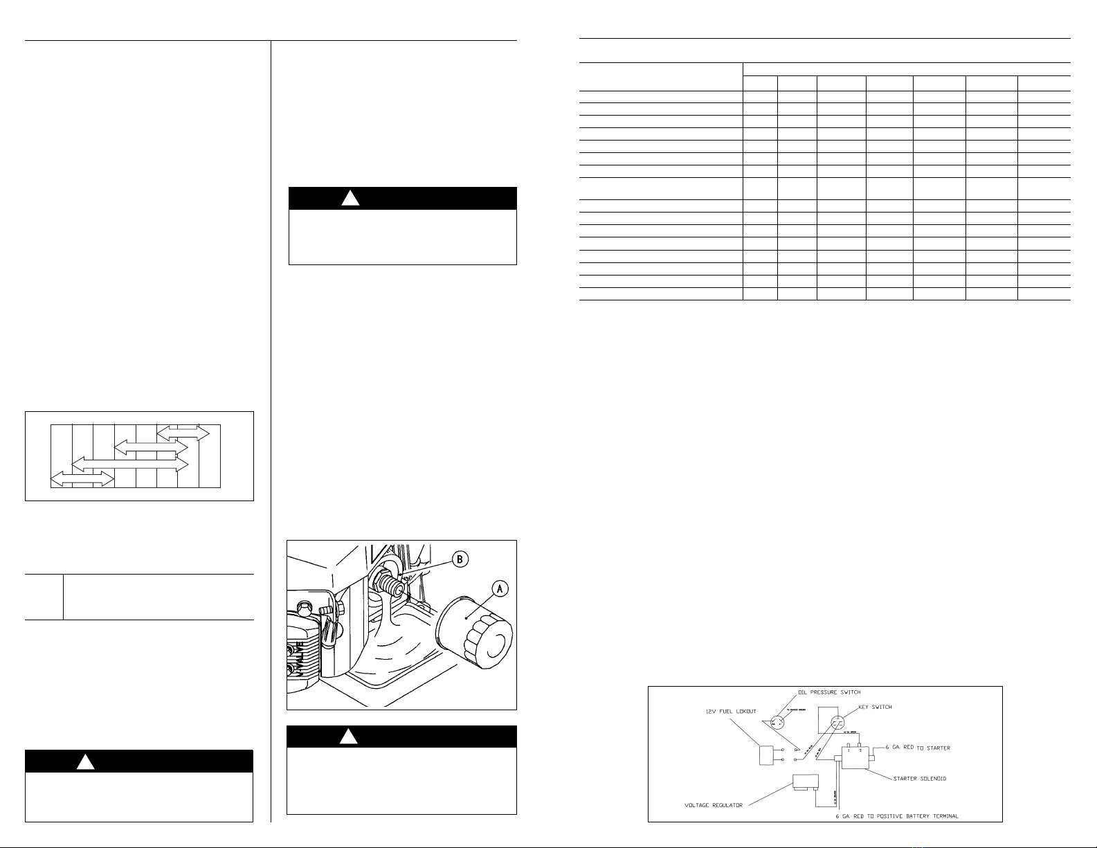
Oil Filter Change
•Change the oil filter every 100 hours of
operation.
WARNING!
Hot engine oil can cause severe burns. Allow
engine temperature to drop from hot to warm
level before attempting to remove oil filter.
CAUTION! Before removing the oil filter,
place a suitable pan under filter connection.
•Drain engine oil into a suitable container.
•Rotate the oil filter (A) counterclockwise to
remove it.
•Coat a film of clean engine oil on seal of new
filter.
•Install new filter rotating it clockwise until
seal contacts mounting surface (B). Then
rotate filter 3/4 turn more by hand.
•Supply engine oil as specified.
•Run the engine for about 3 minutes, stop
engine, and check oil leakage around the filter.
•Add oil to compensate for oil level drop due
to oil filter capacity (See “Oil Level Check”
on page 3).
WARNING!
Engine oil is a toxic substance. Dispose of
used oil properly. Contact you local authorities
for approved disposal methods or possible
recycling.
KAWASAKI ENGINE MAINTENANCE SCHEDULE
INTERVAL
MAINTENANCE Daily First 8 hr. Every 25 Hr. Every 50 hr. Every 100 hr. Every 200 hr. Every 300 hr.
Check and add engine oil •
Check for loose or lost nuts and screws •
Check for fuel and oil leakage •
Check battery electrolyte level •
Check or clean air intake screen •
Clean air cleaner foam element •
Clean air cleaner paper element •
Clean dust and dirt from cylinder and
cylinder head fins •
Tighten nuts and screws •
Change engine oil • •
Clean and gap spark plugs •
Change oil filter •
Replace air cleaner paper element •
Clean combustion chambers •
Clean and adjust valve clearance •*•
Clean and lap valve seating surface •
*After the 1st 50 hours
!
ENGINE TROUBLESHOOTING
COMMON PROBLEMS & PROBABLE CAUSES SOLUTIONS
Engine cranks but will not start
•Fuel cylinder is empty Refill cylinder
•Shutoff valve is closed Open valve
•Clogged, obstructed, kinked or cut fuel or vacuum line Remove obstruction or replace line
•Spark plug lead disconnected Connect lead to spark plug
•Faulty choke or throttle settings Set controls to correct positions
•Faulty ignition coil Replace coil
•Faulty kill switch Replace switch
•Faulty regulator Replace regulator
Engine starts hard
•Faulty choke or throttle settings Set controls to correct position
•Clogged, obstructed, kinked or cut fuel or vacuum line Remove obstruction or replace line
•Faulty regulator Replace regulator
•Low compression Have engine serviced by a trained technician
Engine will not crank
•Battery is discharged Charge or replace battery
•Loose or faulty connections or wires Tighten, repair or replace wires
•Faulty ignition key switch or starter control switch Repair or replace switch(es)
Engine overheats
•Incorrect fuel settings Have engine serviced by a trained technician
•Air intake filter screen or cooling fins clogged Clean and clear debris or replace filter
•Low oil level Check and add oil
Exhaust emissions or propane odor
•Carburetor or regulator setting incorrect Have engine serviced by a trained technician
•Dirty or clogged air filter Replace air filter
•Choke engaged Adjust to correct settings
•Loose fittings, clamps or hoses cracked, hoses cut or leaking Tighten or seal; check with soap and water solution,
if bubbles appear, part is still leaking; replace
KAWASAKI ENGINE BATTERY START WIRING DIAGRAM
-20˚C -10˚C 0˚C 10˚C 20˚C 30˚C 40˚C
-4˚F 14˚F 32˚F 50˚F 68˚F 88˚F 104˚F
SAE5W-20
SAE30
SAE40
SAE10W-30/SAE10W-40
Other manuals for SIDEWINDER 24
2
This manual suits for next models
1
Table of contents
Other Aztec Cleaning Equipment manuals
Popular Cleaning Equipment manuals by other brands

HB-THERM
HB-THERM M8146-EN Assembly instructions

Larson Electronics
Larson Electronics IND-HVAC-DTW-UVC-R1-SS Series Instruction guide

Becca
Becca Solvent Saver 9711 Operator's guide

Meech
Meech CyClean Series operating manual

Biosecurity Technology
Biosecurity Technology Bio-Safe quick start guide

Homeright
Homeright Deck Pro StainStick With Gap Wheel instructions