banks PowerPDA 61100 Safety guide

05/22/07 PN 96803 v.3.0
Banks PowerPDA®
Software &
Installation Kit
(For use with OttoMind®6 tuners)
For use with Palm® Tungsten™ E2 only
2001-2005 Chevy Duramax
2003-2006 Dodge Cummins
2003-2006 Ford Power Stroke
THIS MANUAL IS FOR USE WITH KITS 61100, 61102, 61104, 61106,
61108, 61110, 61112
Gale Banks Engineering
546 Duggan Avenue • Azusa, CA 91702
(626) 969-9600 • Fax (626) 334-1743
Product Information & Sales: (800) 438-7693
Customer Support: (888) 839-5600
Installation Support: (888) 839-2700
bankspower.com
©2007 Gale Banks Engineering

2 96803 v.3.0

96803 v.3.0 3
Table of Contents
Introduction. . . . . . . . . . . . . . . . . . . . 4
Section 1 . . . . . . . . . . . . . . . . . . . . . . 5
Charging the PDA
Section 2 . . . . . . . . . . . . . . . . . . . . . . 6
Installing the Banks PowerPDA Software
Section 3 . . . . . . . . . . . . . . . . . . . . . . 8
Mounting the Docking Station and
Connecting the Banks PowerPDA
Section 4 . . . . . . . . . . . . . . . . . . . . . 20
Software Introduction
Section 5 . . . . . . . . . . . . . . . . . . . . . 20
Changing Power Levels
Section 6 . . . . . . . . . . . . . . . . . . . . . 21
System Menu
Section 7 . . . . . . . . . . . . . . . . . . . . . 22
Sleep Mode and Power Save Setting
Section 8 . . . . . . . . . . . . . . . . . . . . . 24
System Monitors
Section 9 . . . . . . . . . . . . . . . . . . . . . 26
Gauge Set-Up
Section 10 . . . . . . . . . . . . . . . . . . . . 27
On Screen Alerts
Section 11 . . . . . . . . . . . . . . . . . . . . 29
Checking and Clearing OBD II Diagnostic
Codes
Section 12 . . . . . . . . . . . . . . . . . . . . 30
Performance Testing
Section 13 . . . . . . . . . . . . . . . . . . . . 32
Self Diagnostics
Section 14 . . . . . . . . . . . . . . . . . . . . 33
Recalibration for Non-Stock Tire Sizes
(and Non-Stock Gear Ratios)
Section 15 . . . . . . . . . . . . . . . . . . . . 35
Exiting the Banks PowerPDA Application
Section 16 . . . . . . . . . . . . . . . . . . . . 36
Troubleshooting

4 96803 v.3.0
The Banks PowerPDA is a versatile
touch-screen interface to the
OttoMind®6 tuner and your truck. With
the push of a button, you can change
power levels on-the-fly. It displays
four engine functions at a time, two
of which are user-selectable (over a
dozen to choose from). It will clock
your 0-60 mph, 1⁄8-mile and 1⁄4-mile
performance runs, recording peak
boost and EGT values. Performance
runs are automatically stored for later
retrieval with a time-and-date stamp.
With The Banks PowerPDA, you can
also scan and clear OBD II diagnostic
codes. It gives you the endless
functionality of a Palm® Tungsten™
E2 PDA, and fits in a custom docking
station using infrared wireless
connectivity.
Introduction
Figure 1 Front view
HOME KEY
MENU KEY
CENTER BUTTON
5-WAY
NAVIGATOR
(UP)
(DOWN)

The Palm Tungsten E2 will need to be
charged for a minimum of one hour
before the unit will function. The Palm
Tungsten E2 can be charged either by
the supplied AC-outlet wall charger
or by the integrated charging cable
in the Docking Station. The unit will
be fully charged in one to two hours.
After a minimum charge of one hour,
press the power button to turn on the
Banks PowerPDA. (See Figure 1 and
2) Follow the on-screen instructions
to set-up the Palm Tungsten E2 The
Palm Tungsten E2 will ask for time,
date, time zone and require that you
perform an on-screen stylus accuracy
test. (See Figure 3 and 4). Once initial
setup is complete the Palm Tungsten
E2 will be ready for the Banks
PowerPDA software installation.
-END, SECTION 1-
Section 1
CHARGING THE PDA
Figure 2 Top view
96803 v.3.0 5
Figure 3 Figure 4
EXPANSION SLOT POWER BUTTON

6 96803 v.3.0
The Banks PowerPDA software is
supplied on a Secure Digital (SD)
media card. The software should be
installed on the Palm Tungsten E2
and run from main memory. You can
use the additional space on the SD
card to store music, photos and other
data. Refer to your device instruction
manual for using SD cards to store
data. You should leave a copy of the
Banks PowerPDA software on the SD
card as a backup for future reference.
1. Insert the SD card into the slot on
the top of the Palm Tungsten E2.
Note: the contents of the SD card
should appear on the screen. (The
“Banks” Icon). (See Figure 1)
2. Select the ‘Menu’ button on the
bottom of the Palm Tungsten E2
(beneath the ‘Home’ key). Then select
‘Copy’. (See Figure 5)
3. In the ‘Copy From’ drop down
Section 2
INSTALLING THE BANKS POWERPDA SOFTWARE
Figure 5
Figure 6
Figure 7
Figure 8

96803 v.3.0 7
menu select “Card”. (See Figure
6) The ‘Copy To’ selection will
automatically change to “Device”. (See
Figure 7) select on the “Banks” icon,
if it is not selected or there is more
than one item in the list. Touch the
“Copy” button. (See Figure 8) A dialog
box will appear, indicating the Palm
Tungsten E2 is copying the software
from the SD card. Once completed,
press the “Done” button.
4. Select the drop-down menu in the
upper right hand corner of the screen.
Touch the button labeled ‘All’. The
Banks PowerPDA software is now
installed. You may now remove the SD
Card from its slot.
5. To start the Banks PowerPDA
software touch the icon called
“Banks”. (See Figure 9)
-END, SECTION 2-
Figure 9

8 96803 v.3.0
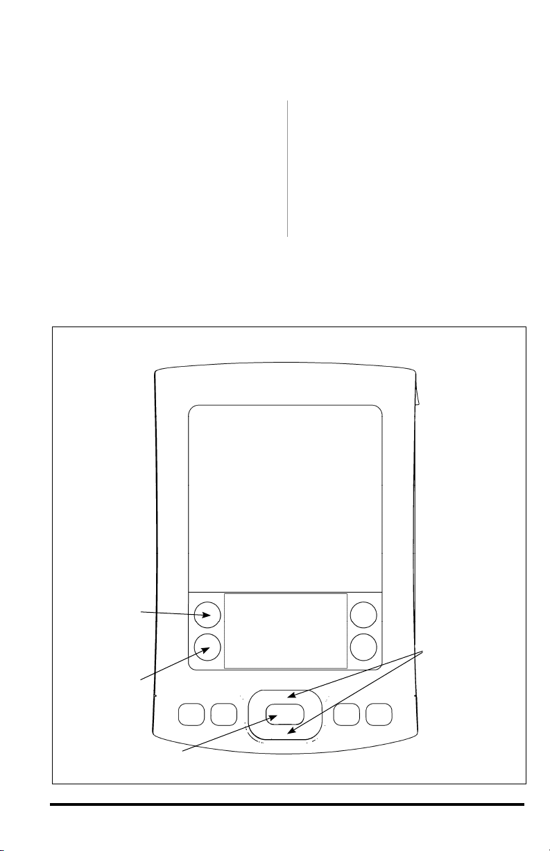
Note: This system has been
designed for use with the Palm
Tungsten E2 PDA.
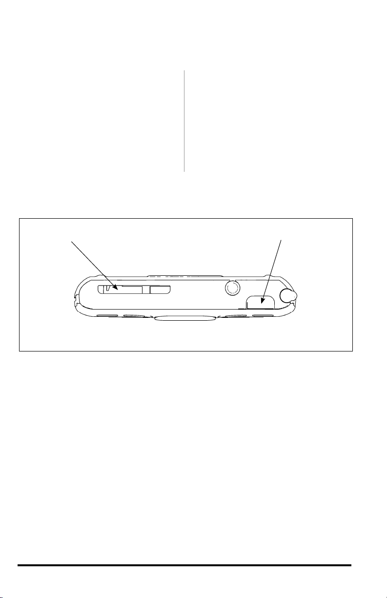
Warning: The PDA may be
susceptible to damage as a result
of extended exposure to sunlight,
heat or extreme cold. It is highly
recommended that the PDA
be removed from its mounting
location if the vehicle will be
subjected to high concentrations
of sunlight, heat or cold for
an extended period of time.
Gale Banks Engineering is not
responsible for damage to PDAs
resulting from exposure conditions.
Locate the Docking Station in your kit.
The mounting location of the Docking
Station is vehicle specific. It is not a
universal fit. Make sure to do a dry pre-
fit before permanently mounting. For
mounting locations, refer to the following
figures:
Figure 11 – Chevy/GMC
Figure 15 – Dodge
Figure 22 – Ford (’03-’04)
Figure 25 – Ford (’05-’06)
Note: In cold climates, best results will
be obtained if the vehicle’s heater is
run to bring the inside temperature up
to “room temperature” (at least 68°F).
1. Clean mounting area with isopropyl
alcohol or similar residue-free cleaning
agent to prepare the surface for the
adhesive tape.
2. The Docking Station has adhesive
tape applied to it at the factory. Prior
to removing the protective liner from
the tape, test fit the unit on the dash
as indicated in the appropriate photo.
Refer to the figure list above for
vehicle-specific mounting locations.
The Docking Station will fit the dash
contours only where shown in the
photos.
3. After test fitting, remove the liner
from the adhesive tape on the back of
the Docking Station.
4. Carefully align and secure the
Docking Station to the dash in the
same location as it was test fit. Press
the Docking Station firmly against the
dash for one minute to ensure good
adhesion.
Vehicle specific instructions follow.
For Chevy/GMC, proceed to step 5.
For Dodge, proceed to step 15.
For Ford (’03-’04) proceed to step 15.
For Ford (’05), proceed to step 34.
Chevy/GMC
5. Locate the two self-drilling screws
supplied in your kit.
6. Install the screws through the
two access holes in the right side of
the Docking Station. Doing this will
put two permanent holes in the
dashboard panel. Be certain of the
location of the Docking Station
before installing the screws.
7. Two push-in plastic plugs are
provided to cover the two screw
access holes in the Docking Station.
Install the plugs at this time.
Note: The Docking Station must
be connected to the previously
installed Banks PowerPDA-compatible
OttoMind6 tuner via the OBD II
interface cable. If your OttoMind6
tuner is not installed, refer to the
OttoMind6 tuner owner’s manual to
install the tuner before proceeding.
8. Locate the Banks OBD II Interface
Cable in your kit. This cable has
three connection points. Connect the
red OBD II connector on the Banks
interface cable to the vehicle OBD II
connector. Use a cable tie as shown
in Figure 10 to secure the Banks
interface cable to the vehicle OBD II
connector. Next, connect the
Section 3
MOUNTING THE DOCKING STATION AND CONNECTING THE BANKS
POWERPDA

96803 v.3.0 9
Figure 10 Chevy/GMC
Figure 11 Chevy/GMC

10 96803 v.3.0
6-pin connector on the Banks OBD II
interface cable to the 6-pin connector
on the OttoMind6 Tuner harness.
9. Finally, unclip the dashboard
panel, starting with the lower right
hand corner. (See Figures 11-14) Pry
and unclip as needed to gain enough
clearance to route the RJ12 cable
(simular to telephone connector)
behind the panel, along its lower edge.
10. Locate the RJ12 connector portion
on the Banks interface cable and pull
enough cable through to reach the
bottom of the Docking Station.
11. Connect the RJ12 cable into the
left-most receptacle on the bottom of
the Docking Station.
Warning: The charging cable on
the Docking Station is designed
to supply a constant low-voltage
power source (+5VDC) to the Banks
PowerPDA and is “live” as long
as the system’s OBD II interface
cable is completely installed and
the RJ12 connector is plugged into
the Docking Station. Although
this charging cable is short and its
circuitry is fuse-protected, the user
is expected to take appropriate
measures to prevent small children
and/or pets from contact with any
part of this system.
12. Refit the dash panel by carefully
snapping it back into place. Tuck any
excess cable behind it for a clean
appearance.
13. Your Docking Station is now
installed and is ready for the
Banks PowerPDA. Install the Banks
PowerPDA into the Docking Station.
Be sure the Banks PowerPDA is
completely seated in the Docking
Station against the lower support
bracket.
14. Plug the Docking Station’s
charging cable into the charging
receptacle on the lower edge of the
Banks PowerPDA.
NOTE: There may be a snug fit when
installing the Banks PowerPDA into the
Docking Station. Take care not to force
this process.
Figure 12 Chevy/GMC

96803 v.3.0 11
Figure 14 Chevy/GMC
Figure 13 Chevy/GMC

Dodge
Note: The Docking Station must
be connected to the previously
installed Banks PowerPDA-compatible
OttoMind6 tuner via an RJ12 cable
(simular to telephone connector). If
your OttoMind6 tuner is not installed,
refer to the OttoMind6 tuner owner’s
manual to install the tuner before
proceeding.
15. To route the RJ12 cable
connecting the Docking Station to the
OttoMind6 (see OttoMind6 owners
manual for details), you will need to
unclip the knee panel (See Figure
16) Pry and unclip as needed to gain
enough clearance to route the cable
behind the panel.
16. Locate the RJ12 cable on your
OttoMind6 wiring harness and pull
enough cable through to reach the
bottom of the Docking Station.
17. Locate and remove the screw
in the dash panel above the hook as
shown in Figure 17.
18. Remove the dash panel by gently
pulling and unclipping it as needed.
(See Figure 18).
19. Guide the RJ12 cable through the
clearance between the removed panel
and the dash as shown in Figure 19.
20. Looking at the back of the dash
panel, locate the screw for the dash
plate as shown in Figure 20. This
panel may be blank, or contain the
airbag deactivation switch. Remove
the screw and the plate.
21. Route the RJ12 cable through
the opening and connect it to the left
most receptacle on the bottom of the
Docking Station. Replace the dash
plate and screw.
Warning: The charging cable on
the Docking Station is designed
to supply a constant low-voltage
power source (+5VDC) to the Banks
PowerPDA and is “live” as long
as the system’s OBD II interface
cable is completely installed and
the RJ12 connector is plugged into
the Docking Station. Although
this charging cable is short and its
circuitry is fuse-protected, the user
is expected to take appropriate
measures to prevent small children
and/or pets from contact with any
part of this system.
Figure 15 Dodge
12 96803 v.3.0

Figure 16 Dodge
Figure 17 Dodge
96803 v.3.0 13

22. Refit the dash panel and knee
panel by carefully snapping them back
into place. Tuck any excess cable
behind it for a clean appearance. (See
Figure 21)
23. Your Docking Station is now
installed and is ready for the
Banks PowerPDA. Install the Banks
PowerPDA into the Docking Station.
Be sure the Banks PowerPDA is
completely seated in the Docking
Station against the lower support
bracket.
24. Plug the Docking Station’s
charging cable into the charging
receptacle on the lower edge of the
Banks PowerPDA.
NOTE: There may be a snug fit when
installing the Banks PowerPDA into the
Docking Station. Take care not to force
this process.
Figure 18 Dodge
Figure 19 Dodge
14 96803 v.3.0

Figure 20 Dodge
Figure 21 Dodge
96803 v.3.0 15

Ford (’03-04)
25. Locate the self-drilling screw
supplied in your kit.
26. Install the screw through the
large access hole in the bottom of the
Docking Station. Doing this will put
a permanent hole in the dashboard
panel. Be certain of the location
of the Docking Station before
installing the screw.
Note: The Docking Station must
be connected to the previously
installed Banks PowerPDA-
compatible OttoMind6 tuner via an
RJ12 cable (simular to telephone
connector). If your OttoMind6
tuner is not installed, refer to the
OttoMind6 tuner owner’s manual to
install the tuner before proceeding.
27. Remove the fuse access panel
below the steering column. It is
secured by four 1⁄4-turn plastic screws.
28. Remove the smaller dash panel
immediately to the right as shown in
Figures 23 and 24. Unclip it by pulling
in the area shown in the picture.
29. Locate the RJ12 cable from
your OttoMind6 Wiring harness and
route it to the bottom of the Docking
Station behind the panels you’ve just
removed.
30. Connect the RJ12 cable to the
left-most receptacle on the bottom of
the Docking Station.
Warning: The charging cable on
the Docking Station is designed
to supply a constant low-voltage
power source (+5VDC) to the Banks
PowerPDA and is “live” as long
as the system’s OBD II interface
cable is completely installed and
the RJ12 connector is plugged into
the Docking Station. Although
this charging cable is short and its
circuitry is fuse-protected, the user
is expected to take appropriate
measures to prevent small children
and/or pets from contact with any
part of this system.
31. Refit the dash panel by carefully
snapping it back into place. Refit
the fuse access panel using the four
fasteners removed earlier. Tuck any
excess cable behind the panels for a
clean appearance.
32. Your Docking Station is now
installed and is ready for the
Banks PowerPDA. Install the Banks
PowerPDA into the Docking Station.
Figure 22 Ford (’03-’04)
16 96803 v.3.0

Figure 23 Ford (’03-’04)
Be sure the Banks PowerPDA is
completely seated in the Docking
Station against the lower support
bracket.
33. Plug the Docking Station’s
charging cable into the charging
receptacle on the lower edge of the
Banks PowerPDA.
NOTE: There may be a snug fit when
installing the Banks PowerPDA into the
Docking Station. Take care not to force
this process.
Figure 24 Ford (’03-’04)
96803 v.3.0 17

Ford (’05-’06)
Note: The Docking Station must
be connected to the previously
installed Banks PowerPDA-compatible
OttoMind6 tuner via an RJ12 cable. If
your OttoMind6 tuner is not installed,
refer to the OttoMind6 tuner owner’s
manual to install the tuner before
proceeding.
34. Remove the fuse access panel
below the steering column by pulling
on it with the handles as shown in
Figure 26.
35. Remove the smaller dash panel
immediately to the right as shown in
Figure 27. Unclip it by pulling in the
area shown in the picture.
36. Locate the RJ12 cable from
your OttoMind6 Wiring harness and
route it to the bottom of the Docking
Station behind the panels you’ve just
removed.
37. Connect the RJ12cable to the left-
most receptacle on the bottom of the
Docking Station.
Warning: The charging cable on
the Docking Station is designed
to supply a constant low-voltage
power source (+5VDC) to the Banks
PowerPDA and is “live” as long
as the system’s OBD II interface
cable is completely installed and
the RJ12 connector is plugged into
the Docking Station. Although
this charging cable is short and its
circuitry is fuse-protected, the user
is expected to take appropriate
measures to prevent small children
and/or pets from contact with any
part of this system.
38. Refit the dash panel by carefully
snapping it back into place. Refit the
fuse access panel and tuck any excess
cable behind the panels for a clean
appearance.
38. Your Docking Station is now
installed and is ready for the
Banks PowerPDA. Install the Banks
PowerPDA into the Docking Station.
Be sure the Banks PowerPDA is
completely seated in the Docking
Station against the lower support
bracket.
40. Plug the Docking Station’s
charging cable into the charging
receptacle on the lower edge of the
Banks PowerPDA.
NOTE: There may be a snug fit when
installing the Banks PowerPDA into the
Docking Station. Take care not to force
this process.
-END, SECTION 3-
Figure 25 Ford (’05-’06)
18 96803 v.3.0

Figure 26 Ford (’05-’06)
Figure 27 Ford (’05-’06)
96803 v.3.0 19

20 96803 v.3.0
To change between power levels
use the 5-way navigator button. (See
Figure 1)
1. Press the navigator button up to
increase the displayed power level.
2. Press the navigator button down to
decrease the displayed power level.
Note: The selectable power levels are
1 thru 6. Level 1 produces stock power
and level 6 produces the maximum
power. The selection of a power level
can be done with the vehicle on, off
(when the Banks PowerPDA is on), or
while driving.
-END, SECTION 5-
Section 5
CHANGING POWER LEVELS
With the key in the ‘ON’ position, turn
the Banks PowerPDA on and click
on the “Banks” icon. (See Figure
28) The Banks PowerPDA software
will initialize and the System Monitor
screen will appear. (See Figure 29)
The default System Monitor screen
shows the following: four Gauges,
Power Level, OttoMind6 Tuner Status,
Hist-O-Graph and a status window.
The System Monitor is the Banks
PowerPDA’s main screen.
-END, SECTION 4-
Section 4
SOFTWARE INTRODUCTION
Figure 28 Figure 29
This manual suits for next models
6
Table of contents
Other banks Automobile Accessories manuals
Popular Automobile Accessories manuals by other brands

Oasis Charger
Oasis Charger JuiceBar 320 Series instruction manual

Bestop
Bestop Tigertop Installation instructions and owner's manual

GReddy
GReddy Type 31 installation guide

Quadratec
Quadratec Ski & Snowboard Rack installation manual

Menabo
Menabo KIT+1 MERAK Fitting instructions

Whispbar
Whispbar K355W Fitting instructions