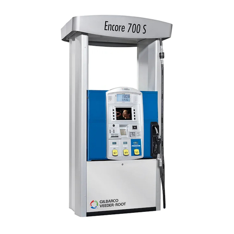
GILBARCO VEEDER-ROOT Latitude LS-100 User manual

LATITUDE™
Installation Manual
MDE-5427E

Computer Programs and Documentation
All Gilbarco Inc. and/or Veeder-Root Company computer programs (including software on diskettes and within memory chips) and documentation are copyrighted by, and shall
remain the property of, Gilbarco Inc. and/or Veeder-Root Company. Such computer programs and documents may also contain trade secret information. The duplication, disclosure,
modification, or unauthorized use of computer programs or documentation is strictly prohibited, unless otherwise licensed by Gilbarco Inc. and/or Veeder-Root Company.
Federal Communications Commission (FCC) Warning
This equipment has been tested and found to comply with the limits for a Class A digital device pursuant to Part 15 of the FCC Rules. These limits are designed to provide
reasonable protection against harmful interference when the equipment is operated in a commercial environment. This equipment generates, uses, and can radiate radio frequency
energy, and if not installed and used in accordance with the instruction manual, may cause harmful interference to radio communications. Operation of this equipment in a
residential area is likely to cause harmful interference in which case the user will be required to correct the interference at his own expense. Changes or modifications not expressly
approved by the manufacturer could void the user’s authority to operate this equipment.
Approvals
Trademarks
National Conference of Weights and Measures (NCWM) - Certificate of Conformance (CoC):
Gilbarco pumps and dispensers are evaluated by NCWM under the National Type Evaluation Program (NTEP). NCWM has issued the following CoC:
CoC# Product Model # CoC# Product Model #
02-019 Encore Nxx 02-036 Legacy Jxxx
02-020 Eclipse Exx
02-037
G-SITE Printer (Epson) PA0307
02-025 Meter - C Series PA024NC10 G-SITE Distribution Box PA0306
Meter - C Series PA024TC10 G-SITE Keyboard PA0304
02-029 CRIND — G-SITE Mini Tower PA0301
02-030
TS-1000 Console — G-SITE Monitor PA0303
TS-1000 Controller PA0241 G-SITE Printer (Citizen) PA0308
Distribution Box PA0242 02-038 C+ Meter T19976
Meter - EC Series PA024EC10 02-039 Passport PA0324
VaporVac Kits CV 02-040 Ecometer T20453
05-001 Titan KXXY Series
Gilbarco is an ISO 9001:2008 registered company.
Underwriters Laboratories (UL):
UL File# Products listed with UL
MH1941 All Gilbarco pumps and dispensers that bear
the UL listing mark.
MH8467 Transac System 1000 and PAM 1000
E105106 Dell DHM Minitower
E165027 G-SITE and Passport Systems
California Air Resources Board (CARB):
Executive Order # Product
G-70-52-AM Balance Vapor Recovery
G-70-150-AE VaporVac
Additional U.S. and foreign trademarks pending.
All product names, logos, and brands are the property of their respective owners and are for identification
purposes only. Use of these names, logos, and brands does not imply endorsement.
This document is subject to change without notice.
http://www.gilbarco.com
2022 Gilbarco Inc. All Rights Reserved
Service mark
GOLDSM
Non-registered trademarks
Applause™ Media System Gilbert™Optimum™ Series Tank Monitor™
CIM™G-SITE™PAM™ TCR
™
C-PAM™G-SITE® Link™PA M™ 1000 The Advantage™ Series
Dimension™ Series G-SITE® Lite™PA M™ 5000 Titan™
Ecometer™Highline™Passport™Trimline™
Eclipse™Horizon™SMART Connect™Ultra-Hi™
ECR™InfoScreen™SMART CRIND™ValueLine™
e-CRIND™Insite360™SMART Meter™
EMC™Making Things Better™SmartPad™
FlexPay™MPD™Super-Hi™
G-CAT™MultiLine™Surge Management System™
Registered trademarks
CRIND®
Encore®
Gilbarco®
Legacy®
Performer®
Transac®
Transac® System 1000
TRIND®
Va p o r Va c ®

MDE-5427E Latitude™Installation Manual · July 2022 Page i
Table of Contents
1 – Introduction 1-1
Purpose . . . . . . . . . . . . . . . . . . . . . . . . . . . . . . . . . . . . . . . . . . . . . . . . . . . . . . . . . . . . . . . . . . . . . . . . . . . . . . . . 1-1
Required Tools . . . . . . . . . . . . . . . . . . . . . . . . . . . . . . . . . . . . . . . . . . . . . . . . . . . . . . . . . . . . . . . . . . . . . . . . . . 1-1
Support Information . . . . . . . . . . . . . . . . . . . . . . . . . . . . . . . . . . . . . . . . . . . . . . . . . . . . . . . . . . . . . . . . . . . . . . . 1-1
Related Documents . . . . . . . . . . . . . . . . . . . . . . . . . . . . . . . . . . . . . . . . . . . . . . . . . . . . . . . . . . . . . . . . . . . . . . . 1-2
Abbreviations and Acronyms. . . . . . . . . . . . . . . . . . . . . . . . . . . . . . . . . . . . . . . . . . . . . . . . . . . . . . . . . . . . . . . . 1-2
Common Terms. . . . . . . . . . . . . . . . . . . . . . . . . . . . . . . . . . . . . . . . . . . . . . . . . . . . . . . . . . . . . . . . . . . . . . . . . . 1-3
2 – Important Safety Information 2-1
3 – Hazardous Locations 3-1
Zoning Diagram . . . . . . . . . . . . . . . . . . . . . . . . . . . . . . . . . . . . . . . . . . . . . . . . . . . . . . . . . . . . . . . . . . . . . . . . . . 3-1
4 – Preliminary Installation Information 4-1
Required Equipment and Materials . . . . . . . . . . . . . . . . . . . . . . . . . . . . . . . . . . . . . . . . . . . . . . . . . . . . . . . . . . . 4-1
Preparing for Installation . . . . . . . . . . . . . . . . . . . . . . . . . . . . . . . . . . . . . . . . . . . . . . . . . . . . . . . . . . . . . . . . . . . 4-1
Gaining Access to and from Latitude Cabinet . . . . . . . . . . . . . . . . . . . . . . . . . . . . 4-2
Verifying and Determining Plumbing Requirements . . . . . . . . . . . . . . . . . . . . . . . 4-2
Adapting Pit Box. . . . . . . . . . . . . . . . . . . . . . . . . . . . . . . . . . . . . . . . . . . . . . . . . . . 4-3
Units with Ground Fault Interrupt (GFI)/Residual Current Device (RCD). . . . . . . . 4-3
Dimensions of Latitude Models . . . . . . . . . . . . . . . . . . . . . . . . . . . . . . . . . . . . . . . . . . . . . . . . . . . . . . . . . . . . . . 4-4
5 – Installing Units on Island 5-1
Lifting Latitude Units . . . . . . . . . . . . . . . . . . . . . . . . . . . . . . . . . . . . . . . . . . . . . . . . . . . . . . . . . . . . . . . . . . . . . . 5-1
Mounting Unit to Island . . . . . . . . . . . . . . . . . . . . . . . . . . . . . . . . . . . . . . . . . . . . . . . . . . . . . . . . . . . . . . . . . . . . 5-2
Installation Instructions for Latitude Suction System . . . . . . . . . . . . . . . . . . . . . . . . . . . . . . . . . . . . . . . . . . . . . . 5-3
Installation Instructions for Latitude Pressure System. . . . . . . . . . . . . . . . . . . . . . . . . . . . . . . . . . . . . . . . . . . . . 5-5
Installation Diagram for Latitude . . . . . . . . . . . . . . . . . . . . . . . . . . . . . . . . . . . . . . . . . . . . . . . . . . . . . . . . . . . . . 5-7
Installing the Pump. . . . . . . . . . . . . . . . . . . . . . . . . . . . . . . . . . . . . . . . . . . . . . . . . 5-8
Connecting Pump/Dispenser Inlet Pipes . . . . . . . . . . . . . . . . . . . . . . . . . . . . . . . . . . . . . . . . . . . . . . . . . . . . . . 5-11
Connecting Vapor Return Line to Vapor Shear Valve . . . . . . . . . . . . . . . . . . . . . . . . . . . . . . . . . . . . . . . . . . . . 5-17
Anchoring Pump/Dispenser to Island . . . . . . . . . . . . . . . . . . . . . . . . . . . . . . . . . . . . . . . . . . . . . . . . . . . . . . . . 5-18
6 – Wiring in Unit 6-1
Installing Wiring . . . . . . . . . . . . . . . . . . . . . . . . . . . . . . . . . . . . . . . . . . . . . . . . . . . . . . . . . . . . . . . . . . . . . . . . . . 6-1
Operating Environment . . . . . . . . . . . . . . . . . . . . . . . . . . . . . . . . . . . . . . . . . . . . . 6-1
Wiring External to Dispenser . . . . . . . . . . . . . . . . . . . . . . . . . . . . . . . . . . . . . . . . . 6-1
Supply Connections for Single Phase Pump. . . . . . . . . . . . . . . . . . . . . . . . . . . . . . . . . . . . . . . . . . . . . . . . . . . . 6-4
Supply Connections for Three-phase Pump . . . . . . . . . . . . . . . . . . . . . . . . . . . . . . . . . . . . . . . . . . . . . . . . . . . . 6-5
Supply Connections for Single-phase Dispenser . . . . . . . . . . . . . . . . . . . . . . . . . . . . . . . . . . . . . . . . . . . . . . . . 6-7
Completing Field Wiring . . . . . . . . . . . . . . . . . . . . . . . . . . . . . . . . . . . . . . . . . . . . . . . . . . . . . . . . . . . . . . . . . . 6-13
7 – Installing Breakaways, Hoses, Swivels, and Nozzles 7-1
Units Without Hose Retractors . . . . . . . . . . . . . . . . . . . . . . . . . . . . . . . . . . . . . . . . . . . . . . . . . . . . . . . . . . . . . . 7-2
8 – Completing Installation 8-1
Table of Contents

Table of Contents
Page ii MDE-5427E Latitude™Installation Manual · July 2022
Do Not Turn on AC Power . . . . . . . . . . . . . . . . . . . . . . . . . . . . . . . . . . . . . . . . . . . . . . . . . . . . . . . . . . . . . . . . . .8-1
Installation Checklists . . . . . . . . . . . . . . . . . . . . . . . . . . . . . . . . . . . . . . . . . . . . . . . . . . . . . . . . . . . . . . . . . . . . . .8-1
Mechanical and Hydraulic Related Items . . . . . . . . . . . . . . . . . . . . . . . . . . . . . . . . 8-2
Electrical Related Items . . . . . . . . . . . . . . . . . . . . . . . . . . . . . . . . . . . . . . . . . . . . .8-3
Purging Air from System and Testing. . . . . . . . . . . . . . . . . . . . . . . . . . . . . . . . . . . . . . . . . . . . . . . . . . . . . . . . . .8-4
For New Dispensers (Purging Through Shear Valve). . . . . . . . . . . . . . . . . . . . . . .8-4
Special Steps to Purge Air from Underground Lines . . . . . . . . . . . . . . . . . . . . . . . 8-4
For New and Existing Pumps and Dispensers with Fuel in Lines
(Purging Through Nozzle) . . . . . . . . . . . . . . . . . . . . . . . . . . . . . . . . . . . . . . . . . . . .8-5
Verifying Shear Valve, Nozzle, and Dispenser Shutoff Operation . . . . . . . . . . . . .8-6
Calibration Procedure for Latitude Units. . . . . . . . . . . . . . . . . . . . . . . . . . . . . . . . . . . . . . . . . . . . . . . . . . . . . . . .8-7
Latitude (Liter Unit of Measure). . . . . . . . . . . . . . . . . . . . . . . . . . . . . . . . . . . . . . . . 8-7
Vapor Recovery Adjustment . . . . . . . . . . . . . . . . . . . . . . . . . . . . . . . . . . . . . . . . . .8-7
9 – Reference Information 9-1
Reference Contents . . . . . . . . . . . . . . . . . . . . . . . . . . . . . . . . . . . . . . . . . . . . . . . . . . . . . . . . . . . . . . . . . . . . . . .9-1
Electrical Requirements . . . . . . . . . . . . . . . . . . . . . . . . . . . . . . . . . . . . . . . . . . . . . . . . . . . . . . . . . . . . . . . . . . . .9-2
Plumbing Requirements . . . . . . . . . . . . . . . . . . . . . . . . . . . . . . . . . . . . . . . . . . . . . . . . . . . . . . . . . . . . . . . . . . . .9-9
Pipe Installation. . . . . . . . . . . . . . . . . . . . . . . . . . . . . . . . . . . . . . . . . . . . . . . . . . . .9-9
Pipe Size . . . . . . . . . . . . . . . . . . . . . . . . . . . . . . . . . . . . . . . . . . . . . . . . . . . . . . . .9-10
Appendix: Wiring Diagrams A-1
Index Index-1

Purpose Introduction
MDE-5427E Latitude™Installation Manual · July 2022 Page 1-1
1 – Introduction
Purpose
This manual contains step-by-step instructions for installing Gilbarco® LATITUDE™ pumps
and dispensers. The models include some differences in field wiring, calibration, parameter
setting, and hydraulic connections. This manual does not include site preparation instructions.
After the installation is complete, a Gilbarco-Authorized Service Contractor (ASC) must
commission the unit to activate the warranty. Proper completion of the checklist is required for
commissioning of the unit.
Read and follow all safety precautions outlined in “Important Safety Information” on
page 2-1 and save it in a readily accessible location.
The Latitude dispenser should not be used for biofuel blends of greater than 5%
biodiesel or greater than 10% ethanol without consulting Gilbarco.
IMPORTANT INFORMATION
Required Tools
The following tools are required for installing the Latitude pumps and dispensers:
• Flat-blade and Phillips® Screwdrivers
• 24-mm Nut Driver
• 17-mm Nut Driver
• Hex Key (Allen Key) Set - Metric
• Static Guard Wrist Strap
•Cutters
•Pliers
• Electronic Multimeter
Support Information
For technical assistance, contact Gilbarco Help Desk as follows:
• Middle East Africa (MEA): +9971566441341
• South-East Asia (SEA): +6596723261
• Sub-Saharan Africa (SSA): +27725308637

Introduction Related Documents
Page 1-2 MDE-5427E Latitude™ Installation Manual · July 2022
Related Documents
Document
Number Title GOLDSM Library
MDE-5422 Latitude Owner’s Manual Latitude
MDE-5445 Latitude Service Manual Latitude
MDE-5474 Latitude Programming Quick Reference Guide Latitude
MDE-5475 Calibration Quick Reference Card LATITUDE LS100/200/300 Latitude
MDE-5512 Latitude Multimedia Programming and Service Manual with
Applause™ Media System
Latitude
MDE-5551 Latitude Vapor Recovery and Monitoring System Operational
Manual
Latitude
Abbreviations and Acronyms
Term Description
ASC Authorized Service Contractor
ASTM American Society for Testing and Materials
ATEX Explosive Atmospheres
CAT6 Category 6
CIM™Customer Interface Module
CRIND®Card Reader in Dispenser
GFI Ground Fault Interrupt
GOLD Gilbarco Online Documentation
IFSF International Forecourt Standards Forum
ISD In-station Diagnostic
J-box Junction Box
MEA Middle-East and Africa
MPD Multi Product Dispenser
NEC® National Electrical Code
NPT • National Pipe Taper
• National Pipe Thread
PEI Petroleum Equipment Institute
POS Point of Sale
PTFE PolyTetraFluoroEthylene (chemical name for Teflon®)
PVC Polyvinyl Chloride
RCD Residual Current Device
SEA South-East Asia
SSA Sub-Saharan Africa
STP Submersible Turbine Pump
TCP/IP Transmission Control Protocol/Internet Protocol
TLS Tank Level Sensor
UL®Underwriters Laboratories
UST Underground Storage Tank
W&M Weights and Measures

Common Terms Introduction
MDE-5427E Latitude™Installation Manual · July 2022 Page 1-3
Common Terms
Term Description
Combo This unit is configured as Master on one side and Satellite on the other.
Dispenser A dispensing device that receives fuel under pressure from the Submersible Turbine Pump
(STP) at the Underground Storage Tank (UST).
Grade Fuel that is dispensed and has an assigned price.
Listed Products bearing authorized Listing Mark of Underwriters Laboratories (UL) as
manufacturer’s declaration that product complies with UL’s requirements in accordance
with terms of UL’s Listing and Follow-up Service agreement.
Master This unit dispenses fuel to one saddle tank and to a second saddle tank through a satellite
unit.
Product Refers to fuel in storage tank.
Pump A dispensing device that utilizes a self-contained pumping unit and motor to move fuel
from the storage tank using suction.
Satellite A dispensing unit that receives product from, and registers at the Master unit allowing both
saddle tanks on a vehicle to be filled at the same time.
SMART Meter™Electronic device that measures the flow of product from the UST to the end user.
Te f l o n The DuPont™ trade name for PolyTetraFluoroEthylene (PTFE).

Introduction Common Terms
Page 1-4 MDE-5427E Latitude™ Installation Manual · July 2022
This page is intentionally left blank.

Important Safety Information
MDE-5427E Latitude™Installation Manual · July 2022 Page 2-1
2 – Important Safety Information
Note: Save this Important Safety Information section in a
readily accessible location.
This section introduces the hazards and safety precautions
associated with installing, inspecting, maintaining or servicing
this product. Before performing any task on this product, read
this safety information and the applicable sections in this
manual, where additional hazards and safety precautions for
your task will be found. Fire, explosion, electrical shock or
pressure release could occur and cause death or serious injury,
if these safe service procedures are not followed.
Preliminary Precautions
You are working in a potentially dangerous environment of
flammable fuels, vapors, and high voltage or pressures. Only
trained or authorized individuals knowledgeable in the related
procedures should install, inspect, maintain or service this
equipment.
Emergency Total Electrical Shut-Off
The first and most important information you must know is how
to stop all fuel flow to the pump/dispenser and island. Locate
the switch or circuit breakers that shut off all power to all fueling
equipment, dispensing devices, and Submerged Turbine
Pumps (STPs).
Total Electrical Shut-Off Before Access
Any procedure that requires access to electrical components or
the electronics of the dispenser requires total electrical shut off
of that unit. Understand the function and location of this switch
or circuit breaker before inspecting, installing, maintaining, or
servicing Gilbarco equipment.
Evacuating, Barricading and Shutting Off
Any procedure that requires access to the pump/dispenser or
STPs requires the following actions:
• An evacuation of all unauthorized persons and vehicles from
the work area
• Use of safety tape, cones or barricades at the affected unit(s)
• A total electrical shut-off of the affected unit(s)
Read the Manual
Read, understand, and follow this manual and any other labels
or related materials supplied with this equipment. If you do not
understand a procedure, call a Gilbarco Authorized Service
Contractor. It is imperative to your safety and the safety of
others to understand the procedures before beginning work.
Follow the Regulations
All national regulations related to installation, commissioning,
maintenance, and repair must be observed.
Replacement Parts
Use only genuine Gilbarco replacement parts and retrofit kits on
your pump/dispenser. Using parts other than genuine Gilbarco
replacement parts could create a safety hazard and violate
local regulations.
Safety Symbols and Warning Words
This section provides important information about warning
symbols and boxes.
Alert Symbol
This safety alert symbol is used in this manual and on
warning labels to alert you to a precaution which must be
followed to prevent potential personal safety hazards. Obey
safety directives that follow this symbol to avoid possible injury
or death.
Signal Words
These signal words used in this manual and on warning labels
tell you the seriousness of particular safety hazards. The
precautions below must be followed to prevent death, injury or
damage to the equipment:
DANGER: Alerts you to a hazard or unsafe practice
which will result in death or serious injury.
WARNING: Alerts you to a hazard or unsafe practice
that could result in death or serious injury.
CAUTION with Alert symbol: Designates a hazard or
unsafe practice which may result in minor injury.
CAUTION without Alert symbol: Designates a hazard or
unsafe practice which may result in property or
equipment damage.
Working With Fuels and Electrical Energy
Prevent Explosions and Fires
Fuels and their vapors will explode or burn, if ignited. Spilled or
leaking fuels cause vapors. Even filling customer tanks will
cause potentially dangerous vapors in the vicinity of the
dispenser or island.
The EMERGENCY STOP, ALL STOP, and
PUMP STOP buttons at the cashier’s station
WILL NOT shut off electrical power to the
pump/dispenser. This means that even if you
activate these stops, fuel may continue to flow
uncontrolled.
You must use the TOTAL ELECTRICAL
SHUT-OFF in the case of an emergency and not
the console’s ALL STOP and PUMP STOP or
similar keys.
!
WARNING
!
!
!
!
Important Safety Information
Page 2-2 MDE-5427E Latitude™Installation Manual · July 2022
No Open Fire
Open flames from matches, lighters, welding torches or
other sources can ignite fuels and their vapors.
No Sparks - No Smoking
Sparks from starting vehicles, starting or using power tools,
burning cigarettes, cigars or pipes can also ignite fuels and their
vapors. Static electricity, including an electrostatic charge on
your body, can cause a spark sufficient to ignite fuel vapors.
Every time you get out of a vehicle, touch the metal of your
vehicle, to discharge any electrostatic charge before you
approach the dispenser island.
Working Alone
It is highly recommended that someone who is capable of
rendering first aid be present during servicing. Familiarize
yourself with Cardiopulmonary Resuscitation (CPR) methods, if
you work with or around high voltages. This information is
available from the American Red Cross. Always advise the
station personnel about where you will be working, and caution
them not to activate power while you are working on the
equipment. Use the Lockout/Tagout procedures. If you are not
familiar with this requirement, refer to this information in the
service manual.
Working With Electricity Safely
Ensure that you use safe and established practices in working
with electrical devices. Poorly wired devices may cause a fire,
explosion or electrical shock. Ensure that grounding
connections are properly made. Take care that sealing devices
and compounds are in place. Ensure that you do not pinch wires
when replacing covers. Follow Lockout/Tagout requirements.
Station employees and service contractors need to understand
and comply with this program completely to ensure safety while
the equipment is down.
Hazardous Materials
Some materials present inside electronic enclosures may
present a health hazard if not handled correctly. Ensure that you
clean hands after handling equipment. Do not place any
equipment in the mouth.
In an Emergency
Inform Emergency Personnel
Compile the following information and inform emergency
personnel:
• Location of accident (for example, address, front/back of
building, and so on)
• Nature of accident (for example, possible heart attack, run
over by car, burns, and so on)
• Age of victim (for example, baby, teenager, middle-age,
elderly)
• Whether or not victim has received first aid (for example,
stopped bleeding by pressure, and so on)
• Whether or not a victim has vomited (for example, if
swallowed or inhaled something, and so on)
IMPORTANT: Use of non-Gilbarco replacement parts, defects
caused by the unauthorized addition of non-Gilbarco items to
Gilbarco equipment or by the unauthorized alteration of
Gilbarco equipment voids this warranty.
IMPORTANT: Oxygen may be needed at scene if gasoline has
been ingested or inhaled. Seek medical advice immediately.
Lockout/Tagout
Lockout/Tagout covers servicing and maintenance of machines
and equipment in which the unexpected energization or start-up
of the machine(s) or equipment or release of stored energy
could cause injury to employees or personnel. Lockout/Tagout
applies to all mechanical, hydraulic, chemical, or other energy,
but does not cover electrical hazards.
Gilbarco Veeder-Root encourages the recycling of our
products. Some products contain electronics, batteries,
or other materials that may require special
management practices depending on your location.
Please refer to your local, state, or country regulations
for these requirements.
Gasoline ingested may cause unconsciousness
and burns to internal organs. Do not induce
vomiting. Keep airway open.
Oxygen may be needed at scene. Seek medical
advice immediately.
WARNING
!
Gasoline inhaled may cause unconsciousness
and burns to lips, mouth and lungs.
Keep airway open.
Seek medical advice immediately.
WARNING
!
Gasoline spilled in eyes may cause burns to eye
tissue.
Irrigate eyes with water for approximately
15 minutes.
Seek medical advice immediately.
WARNING
!
Gasoline spilled on skin may cause burns.
Wash area thoroughly with clear water.
Seek medical advice immediately.
WARNING
!

Important Safety Information
MDE-5427E Latitude™Installation Manual · July 2022 Page 2-3
Hazards and Actions
The following actions are recommended regarding these hazards:
• Do not go near a fuel spill or allow anyone else in the area.
• Use station EMERGENCY CUTOFF immediately. Turn off all system circuit breakers to
the island(s).
• Do not use console E-STOP, ALL STOP, and PUMP STOP to shut off power. These keys
do not remove AC power and do not always stop product flow.
• Take precautions to avoid igniting fuel. Do not allow starting of vehicles in the area. Do
not allow open flames, smoking or power tools in the area.
• Do not expose yourself to hazardous conditions such as fire, spilled fuel or exposed
wiring.
• Call emergency numbers.
General Exclusion
Problems caused by faulty installation are not covered by this warranty. This warranty applies
only if equipment has been installed, used, and maintained in-accordance with Gilbarco
installation, operating, and service instruction.
Use of service personnel other than qualified Gilbarco ASCs without prior approval of
Gilbarco product support department will void payment of the warranty claim in question.
Damage suffered by Gilbarco equipment resulting from shipping, accident, power surges,
neglect, misuse, act of God, or abuse is not covered by this warranty.
Use of non-Gilbarco replacement parts, defect caused by the unauthorized addition of
non-Gilbarco equipment or unauthorized alteration of Gilbarco equipment voids this warranty.
WARNING
Spilled fuels, accidents involving pumps/dispensers, or uncontrolled fuel flow create a
serious hazard.
Fire or explosion may result, causing serious injury or death.
Follow established emergency procedures.
!
Collision of a Vehicle with Unit Fire at Island Fuel Spill

Important Safety Information
Page 2-4 MDE-5427E Latitude™Installation Manual · July 2022
This page is intentionally left blank.

Zoning Diagram Hazardous Locations
MDE-5427E Latitude™Installation Manual · July 2022 Page 3-1
3 – Hazardous Locations
Zoning Diagram
The dispenser must be installed to not compromise the zones illustrated in the following
Figure 3-1 and Figure 3-2 on page 3-2.
The zones 0, 1, and 2 indicated in the zoning diagrams define the probability of the hazard
actually being present in flammable concentrations.
•Zone 0: A place in which an explosive atmosphere is present continuously or for long
periods or frequently.
•Zone 1: A place in which an explosive atmosphere is likely to occur in normal operation
occasionally.
•Zone 2: A place in which an explosive atmosphere mist is not likely to occur in normal
operation but, if it does occur, will persist for a short period only.
Figure 3-1: Zoning Diagram for LS-200 Lane Configuration
Zone 0 Zone 1 Zone 2

Hazardous Locations Zoning Diagram
Page 3-2 MDE-5427E Latitude™Installation Manual · July 2022
Figure 3-2: Zoning Diagram for LS-100 and LS-200 Island Configuration
Zone 0 Zone 1 Zone 2

Zoning Diagram Hazardous Locations
MDE-5427E Latitude™Installation Manual · July 2022 Page 3-3
Figure 3-3: Zoning Diagram for LS-300
Zone 0 Zone 1 Zone 2
External Zoning
Hazardous Area For 4 Grade Models
Without Hose Retraction Feature
Hazardous Area For 4 Grade Models
With Hose Retraction Feature

Hazardous Locations Zoning Diagram
Page 3-4 MDE-5427E Latitude™Installation Manual · July 2022
This page is intentionally left blank.

Required Equipment and Materials Preliminary Installation Information
MDE-5427E Latitude™Installation Manual · July 2022 Page 4-1
4 – Preliminary Installation Information
Required Equipment and Materials
The following items are required to properly install the equipment:
• Anchor bolts.
• U-bolts for fastening piping to braces.
• Pit box cover plates. Use when required to adapt the unit to pre-existing pit boxes.
• Lifting device (crane, backhoe, forklift, and so on) to move and lift the pump/dispenser.
• Nylon slings (with a safety lift factor of 5) and screw-pin anchor shackles to lift high hose
pump/dispenser.
• Breakaways, hoses, nozzles, and swivels.
• Barricades.
•Ladder.
• Any kits required for upgrading the unit to the customer’s requirements, such as hose
retrievers, and so on.
Preparing for Installation
To prepare for the installation, proceed as follows:
1Read all instructions before you begin.
2Follow all safety precautions:
• Barricade the area.
• Do not allow vehicles in the work area.
• Do not smoke or allow open flames in the work area.
• Do not use power tools in the work area.
• Do not allow unauthorized people into the work area.
• Wear eye protection during the installation.
• Ensure that there is no power supplied to the units until required, as per later installation
steps.
3Use circuit breakers to turn off all power to pumps/dispensers and STPs. Multiple disconnects
may be required.
4Check the following for proper installation, as recommended by other manufacturers:
• Emergency power cut off switch
• Circuit breakers
• STP control relay boxes - dispensers only (see Note 3)
• Isolation relays - dispensers only (see Note 3)
• Conduit and wiring (see Note 1 on page 4-2)
• Grounding
• Shear valves - dispensers only (see Notes 2 and 3 on page 4-2)

Preliminary Installation Information Preparing for Installation
Page 4-2 MDE-5427E Latitude™Installation Manual · July 2022
• Piping and fittings
• Fuel storage tanks
• Pressure regulating valves (aboveground tanks only)
• STP - dispensers only
• Tank and/or line leak detectors
•Pit boxes
• Components must be compatible with the fluid being dispensed. Consult the manufacturer
for information.
Notes: 1) If you are replacing an existing unit, the installer may connect and extend the
existing field wires to the electronics cabinet using an explosion proof Junction Box
(J-box). For details, refer to “Verifying and Determining Plumbing Requirements”.
2) A shear valve is a safety device required for every product line at each dispenser.
Shear valves may also be required for aboveground tank installations and other
installations with pumps. Follow local and state requirements.
3) Some locations require shear valves for vapor lines. Follow local and state
regulation.
5Inspect the pump/dispenser cartons and contents for shipping damage. Gilbarco does not cover
shipping damage under its warranty policy. Notify the shipper of any damage.
6Remove the lower panels (doors) of the pump/dispenser.
7Ensure that the fuel grade for product lines matches the pump/dispenser brand panels and the
foundation layout. Product lines from the island pit box must have labels.
Gaining Access to and from Latitude Cabinet
Latitude cabinets are designed to protect the equipment inside the unit from the elements. The
doors and covers must be installed as directed. For more information, refer to MDE-5422
Latitude Owner’s Manual and MDE-5445 Latitude Service Manual provided by the ASCs
during commissioning.
Verifying and Determining Plumbing Requirements
Before placing a unit on an island, determine the correct location of piping for the unit
involved and the proper orientation of the unit. A common installation error is to install the
units backwards, which will require expensive modifications. This section contains
information regarding plumbing requirements for various models of Latitude dispensers.
Do not make assumptions about configurations based on previous experience, hose
positions, or layout of the unit that you are replacing, whether it is a Gilbarco unit or that
of any other manufacturer.
IMPORTANT INFORMATION

Preparing for Installation Preliminary Installation Information
MDE-5427E Latitude™Installation Manual · July 2022 Page 4-3
Adapting Pit Box
For installation using an existing pit box, some modifications may be required. The following
list highlights the changes that may be required. These installation considerations may also
apply when you are replacing competitive units.
To adapt the plumbing/conduit to Latitude stub up locations:
• Use care in sizing and routing flexible piping to avoid bends that restrict flow. This is
especially critical for pumps, which may have serious issues with flow or noise if the
flexible pipe cross section becomes significantly restrictive.
• Use flexible piping in the pit box for plumbing adaptation. This is applicable only for
suction (pumper) systems; DO NOT use flexible piping on pressure systems. If piping in
the previous box is rigid, use the adaptability of the Latitude hydraulic cabinet inlets and
conduit entry points instead of making modifications to rigid plumbing and conduit in the
pit box.
• When adapting plumbing in the dispenser cabinet, remember that the lower piping cross
brace must be used to secure plumbing above the shear valve and that rigid piping must be
used within the dispenser.
• Modify the pit box rain lip when required (for boxes designed for The Advantage® Series
wide frame units). Modifications will also typically be performed to the Latitude base.
• When adapting a Latitude unit to an existing pit box or one that is not specifically
designed for the unit, the rain lip may require modification or removal. If the rain lip is
removed, the entire base of the dispenser must be sealed to the island. Study the
foundation layouts and the existing pit box to determine if modifications are required
before mounting the unit on the island. When working in this area, refer to the following
warning.
Where fuels are involved, you are working in a potentiality hazardous environment where
fuels and their vapors may be present and could be ignited with sparks from grinding and
cutting tools.
Always conduct work at the required safe distance away from a hazardous area and use
the appropriate tools.
WARNING
Units with Ground Fault Interrupt (GFI)/Residual Current Device (RCD)
A GFI, also referred to as Residual Current Device (RCD) in some regions, consists of a
sensor that detects changes in the current to the load, by comparing the current flowing to the
load and the current flowing from the load. A drop-off in the current equivalent to about 25
milliamperes can turn off all power by tripping a relay within the GFI/RCD within a few
hundredths of a second.
When powering a dispenser with a GFI/RCD, the return neutral of any device to which the
dispenser supplies power must be the same neutral as that of the dispenser. For example, the
STP control relay.

Preliminary Installation Information Dimensions of Latitude Models
Page 4-4 MDE-5427E Latitude™Installation Manual · July 2022
Dimensions of Latitude Models
The following table lists the dimensions details for various Latitude pumps/dispensers:
Type Weight
LS-100 LS-200 LS-300
1P Mono 1P Twin 2P Duo 1P 2P Quad Mono Duo 1P 2P 3P MPD 4P MPD
Suction
Net Weight (kg) 201 206 245 230 300 300 235 272 289 332 375 420
Gross Weight
(kg)
217 222 261 250 320 320 255 292 324 367 410 450
Dimension (cm) 103 x 73 x
185
103 x 73 x
185
103 x 73 x
185
90 x 73 x
225
90 x 73 x
225
90 x 73 x
225
102 x 73 x
225
102 x 73 x
225
130 x 73 x
225
130 x 73 x
225
130 x 73 x
225
130 x 73 x
225
Pressure
Net Weight (kg) 163 168 175 192 230 230 192 204 251 262 300 320
Gross Weight
(kg)
179 184 191 212 250 250 212 224 386 297 330 350
Dimension (cm) 103 x 73 x
185
103 x 73 x
185
103 x 73 x
185
90 x 73 x
225
90 x 73 x
225
90 x 73 x
225
102 x 73 x
225
102 x 73 x
225
130 x 73 x
225
130 x 73 x
225
130 x 73 x
225
130 x 73 x
225
Suction
pressure net
weight (kg)
38 38 70 38 70 70 43 68 38 70 75 100
Figure 4-1: Model Configuration
820-mm 610-mm
2100-mm
High-hose Dual Configuration
975-mm
800-mm 610-mm
1700-mm
Low-hose Configuration Premium Canopy
2150-mm
Other manuals for Latitude LS-100
1
This manual suits for next models
2
Table of contents
Other GILBARCO VEEDER-ROOT Petrol Station Equipment manuals

GILBARCO VEEDER-ROOT
GILBARCO VEEDER-ROOT Latitude LS-100 User manual

GILBARCO VEEDER-ROOT
GILBARCO VEEDER-ROOT Encore 700 S Guide

GILBARCO VEEDER-ROOT
GILBARCO VEEDER-ROOT K35489 User manual

GILBARCO VEEDER-ROOT
GILBARCO VEEDER-ROOT FlexPay IV Quick start guide

GILBARCO VEEDER-ROOT
GILBARCO VEEDER-ROOT Encore 300 Series User manual

GILBARCO VEEDER-ROOT
GILBARCO VEEDER-ROOT FlexPay IV CRIND Advantage Series User manual

GILBARCO VEEDER-ROOT
GILBARCO VEEDER-ROOT FlexPay EPK ECIM RF User manual

GILBARCO VEEDER-ROOT
GILBARCO VEEDER-ROOT FlexPay IV Insite360 Encore User manual