Contents
1 Features .......................................................................................................................................................................... 4
2 Overview .........................................................................................................................................................................5
2.1 System Components ..............................................................................................................................................................................6
2.2 Features .................................................................................................................................................................................................6
2.3 Conguraon via DIP Switch or IO-Link Interface .................................................................................................................................. 6
2.3.1 Outputs .....................................................................................................................................................................................7
2.3.2 Display Invert ............................................................................................................................................................................7
2.4 Status Indicators ....................................................................................................................................................................................7
2.4.1 Zone Indicators (Beams Blocked Segment) .............................................................................................................................. 7
2.4.2 Three-Digit Display ................................................................................................................................................................... 7
2.4.3 Blanking Indicator .....................................................................................................................................................................8
2.4.4 Electronic Conguraon Indicator ............................................................................................................................................8
2.4.5 Receiver Interface Status Indicators .........................................................................................................................................8
2.5 Receiver Gray (Remote Teach) Wire ..................................................................................................................................................... 8
2.6 Scanning Method .................................................................................................................................................................................. 9
2.6.1 Straight Scan ...........................................................................................................................................................................10
2.6.2 Single-Edge Scan .....................................................................................................................................................................10
2.6.3 Double-Edge Scan ...................................................................................................................................................................10
2.6.4 Maximum Scan Times .............................................................................................................................................................11
2.7 Gain Conguraon ............................................................................................................................................................................... 11
2.8 Electronic Alignment Roune ..............................................................................................................................................................12
2.9 Blanking ...............................................................................................................................................................................................12
2.10 Measurement Mode Selecon ..........................................................................................................................................................12
2.11 Analog Output Conguraon ............................................................................................................................................................ 13
2.12 Discrete Output Conguraon ..........................................................................................................................................................14
3 Components and Specicaons .....................................................................................................................................15
3.1 Sensor Models .....................................................................................................................................................................................15
3.2 Cordsets and Connecons ...................................................................................................................................................................15
3.3 Alignment Aids ..................................................................................................................................................................................... 17
3.4 Accessory Mounng Brackets and Stands ...........................................................................................................................................17
3.5 Replacement Parts .............................................................................................................................................................................. 18
3.6 Specicaons .......................................................................................................................................................................................18
3.7 Emier and Receiver Dimensions ....................................................................................................................................................... 19
3.8 Standard Bracket Dimensions ............................................................................................................................................................. 20
4 Installaon and Alignment .............................................................................................................................................21
4.1 Mounng the Emier and Receiver .................................................................................................................................................... 21
4.2 Mechanical Alignment .........................................................................................................................................................................21
4.3 Wiring Diagrams ..................................................................................................................................................................................22
4.4 Opcal Alignment ................................................................................................................................................................................23
5 Receiver User Interface ..................................................................................................................................................25
5.1 Conguraon DIP Switches ................................................................................................................................................................. 25
5.1.1 Scanning Modes (S1 and S2) .................................................................................................................................................. 25
5.1.2 Measurement Modes (S3 and S4) .......................................................................................................................................... 26
5.1.3 Analog Slope (S5) .....................................................................................................................................................................26
5.1.4 Complementary/Alarm (S6) ................................................................................................................................................... 26
5.2 Alignment/Blanking Buon (Electronic Alignment) ............................................................................................................................ 26
5.2.1 Electronic Alignment and Blanking - Receiver Interface ........................................................................................................ 26
5.2.2 Flashing "000" on the 3-Digit Display ..................................................................................................................................... 27
5.3 Gain (Sensivity Adjust) Buon ...........................................................................................................................................................27
5.4 Inverng the 3-Digit Display ................................................................................................................................................................27
5.5 Troubleshoong and Error Codes ....................................................................................................................................................... 27
5.5.1 "Dirty" Channel Indicator ....................................................................................................................................................... 27
6 IO-Link Interface ............................................................................................................................................................28
6.1 Overview ............................................................................................................................................................................................. 28
6.2 IO-Link Prole and Models ...................................................................................................................................................................28
6.3 Hardware Interface ............................................................................................................................................................................. 28
6.3.1 Electrical Interface ..................................................................................................................................................................29
6.3.2 IO-Link Master ........................................................................................................................................................................29
6.4 IODD (IO-Link Device Descripon) ....................................................................................................................................................... 29
6.5 Conguraon Data .............................................................................................................................................................................. 29
6.5.1 Scan Conguraon ................................................................................................................................................................. 29
6.5.2 Blanking Conguraon ........................................................................................................................................................... 30
6.5.3 General Conguraon ............................................................................................................................................................ 31
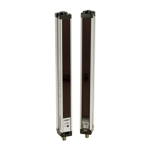
A-GAGE®EZ-ARRAY™IO-Link Instrucon Manual
