P/N64118rev.B
Specifications
10
Banner Engineering Corp. •Minneapolis,U.S.A.
www.bannerengineering.com•Tel:763.544.3164
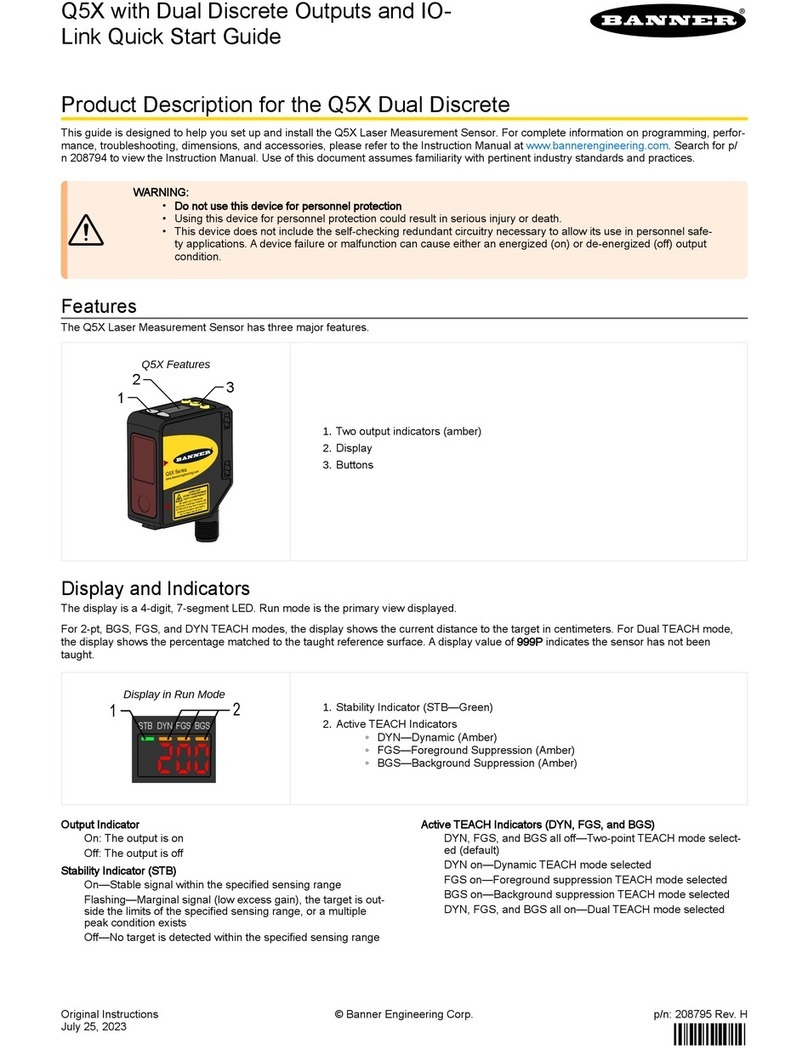
Status Indicators
Power Requirements 16to30Vdc@1.0A(typical:0.5A@16Vdc)
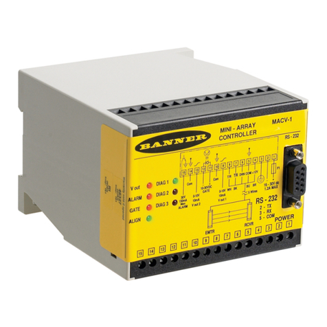
Output 1 (red): LightstoindicateDiscreteOutput#1isactive
Alarm (red): LightstoindicateDiscreteOutput#2isactive
Gate (red): LightstoindicateGATEinputisactive
Align (green): Lightstoindicateemitterandreceiverarealigned
Diagnostics indicator: (Keyoncontrollersidelabel)IdentifiesSystemerrorsandstatus
Inputs Sensor input: Emitterandreceiverwireinparalleltofiveterminals.
Gate input: Opticallyisolated,requires10to30Vdc(7.5kΩimpedance)forgatesignal
Remote alignment input: Opticallyisolated,requires10to30Vdc(7.5kΩimpedance)foralignment
sequencesignal
Discrete (Switched) Outputs NPN outputs:OpencollectorNPNtransistorratedat30Vdcmax.,150mAmax.
PNP outputs: OpencollectorPNPtransistorratedat30Vdcmax.,150mAmax.
All discrete outputs:
OFF-state leakage current: <10µA@30Vdc
ON-state saturation voltage: <1V@10mAand<1.5V@150mA
Serial Data Outputs RS-232orRS-485interface.(Upto15controlmodulesmaybegivenuniqueaddressesononeRS-485
partyline.)
ASCIIorbinarydataformat
9600,19.2K,or38.4Kbaudrate
8databits,1stopbit,andeven,odd,ornoparity
Analog Outputs Voltage-sourcing outputs:0to10Vdc(25mAcurrentlimit)
Current-sinking outputs:4to20mA(16to30Vdcinput)
Resolution: Span/Numberofsensingchannels
Linearity:0.1%offullscale
Temperature variation:0.01%offullscaleper°C
System Programming ViaRS-232interfacetoPC-compatiblecomputerrunningWindows®XP, Vista, or 7andusing
softwaresuppliedwitheachcontrolmodule.
Construction Polycarbonatehousing;mountstoflatsurfaceordirectlyonto35-mmDINrail
Environmental Rating Control Module:NEMA1,IECIP20
Emitter/Receiver:NEMA4,13;IECIP65
Output Configuration MAHCVP-1:TwoPNPdiscrete(switched),two0-10Vvoltagesourcing
MAHCVN-1: TwoNPNdiscrete(switched),two0-10Vvoltagesourcing
MAHCIP-1:TwoPNPdiscrete(switched),two4-20mAcurrentsinking
MAHCIN-1:TwoNPNdiscrete(switched),two4-20mAcurrentsinking
2.2 Control Module Specifications
Operating Conditions Temperature:0°to+50°C(+32°to122°F)
Maximum relative humidity:95%@50°C(non-condensing)
Certifications

