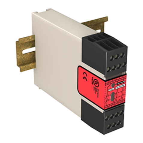
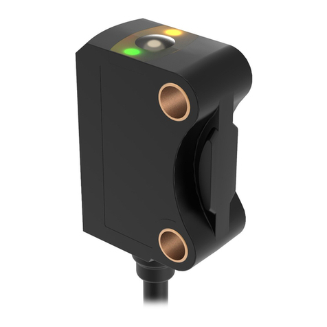
Banner K30 Pro User manual

Original Instructions
June 22, 2023
p/n: 232898 Rev. B
232898
K30 Pro Optical Sensor Quick Start Guide
•
•
•
•
•
•
•
•
•
•
•
•
Quick Start Guide
30 mm Programmable Multicolor RGB Optical Sensor and Indicator
ThisguideisdesignedtohelpyousetupandinstalltheK30 Pro Optical Sensor. For complete information on programming, performance,
troubleshooting,dimensions,andaccessories,pleaserefertotheInstructionManualatwww.bannerengineering.com.Searchforpartnum
ber231384toviewtheInstructionManual.Useofthisdocumentassumesfamiliaritywithpertinentindustrystandardsandpractices.
ProgrammableusingBanner'sProEditorsoftwareandProConverterCable
Upto7colorsinonedevice(14colorsusingProEditor)
Devicesarecompletelyselfcontained—nocontrollerneeded
Teachablemodeswithcolorfeedbackforeaseofuse
Touchlessactivationremovestheneedforphysicalforcetoactivate
RatedIP65
10VDCto30VDCoperation
Resistanttoambientlight,EMI,andRFIinterference
Sensingandindicationinonedevice
WARNING:
Do not use this device for personnel protection
Using this device for personnel protection could result in serious injury or death.
Thisdevicedoesnotincludetheselfcheckingredundantcircuitrynecessarytoallowitsuseinpersonnelsafe
ty applications. A device failure or malfunction can cause either an energized (on) or de-energized (off) output
condition.
Models
** Models with a quick disconnect
require a mating cordset
Family
K30
Color/Control
Q = 5-pin or 8-pin integral
M12 quick disconnect
depending on model **
Q
Connector
M = Momentary
Output
Function
Activation
Method Output State
P AF100 A M
Style
AF100 = 100mm adjustable field*
RGB7 = Programmable Multicolor
AF1000 = 1000mm adjustable field*
Overview
TheK30 Pro Optical Sensorisanadjustablefieldopticalsensorthatcandetectawidevarietyofmaterialsandobjects.
D0
Measurement
Reference Point
D1 D2
Detection Area
Reliable detection of a stationary
and moving object
Detection not
possible
Model D0(mm) SwitchPointD1(mm) SwitchPointD2(mm)
PVS28D 0 20 500
© Banner Engineering Corp.

June 22, 2023page2
K30 Pro Optical Sensor Quick Start Guide
Wiring Diagrams
GRY3 Models
NPN
10-30V dc
–
+
1
3
2
4
5
Load
1
2
PNP
10-30V dc
–
+
1
3
2
4
5
Load
1
2
Pin1=Brown
Pin2=White
Pin3=Blue
Pin4=Black
Pin5=Gray(RemoteInput)
GRY3 Multicolor Color/Function Definition
Green Yellow Red
Input1 X X
Input2 X X
GRY4Models
NPN
10-30V dc
–
+
1
3
2
4
5
Load
Remote Input
1
PNP
10-30V dc
–
+
1
3
2
4
5
Load
Remote Input
1
Pin1=Brown
Pin2=White
Pin3=Blue
Pin4=Black
Pin5=Gray(RemoteInput)
GRY4 Four State Full Logic
NoDetection Detection
NoInput State1:IndicatorOff State3:IndicatorRed
Input1 State2:IndicatorGreen State4:IndicatorYellow
RGB7 Models
NPN
2
7
–
+
1
3
4
8
1
2
3
Load
10-30V dc
PNP
2
7–
+
1
3
4
8
1
2
3
Load
10-30V dc
Pin1=White
Pin2=Brown
Pin3=Green
Pin4=Yellow(RemoteInput)
Pin5=Notused
Pin6=Notused
Pin7=Blue
Pin8=Red
RGB Multicolor Color/Function Definition
Red Yellow Green Cyan Blue Magenta White
Input1 X X X X
Input2 X X X X
Continued on page 3
© Banner Engineering Corp.

K30 Pro Optical Sensor Quick Start Guide
June 22, 2023 page3
Continued from page 2
Red Yellow Green Cyan Blue Magenta White
Input3 X X X X
Configuring a Sensor
TheK30 Pro Optical SensorhasthreeTeachmodes.ThesemodesareindicatedwithaTeachStatuscolor.
The Signal Level color flashes in between the Teach Status color. The color of the Signal Level depends on the signal strength of the target:
Green:Bestsignal,acceptsTeach
Yellow:Acceptablesignal,canacceptTeach
Red:Poorsignal,rejectsTeach
Remote Input
Usetheremoteinputtoprogramthesensorremotely.
The remote input provides limited programming options and is Active High in PNP mode (V+ to brown wire), or Active Low in NPN mode (V+
to blue wire). For Active High, pulse the gray or yellow input wire to V+ (10 V DC to 30 V DC). For Active Low, pulse the gray or yellow input
wiretoground(0VDC).
Theremoteinputwireisenabledbydefault.Pulsetheremoteinputwire7timesorusetheBanner Pro Editorsoftwaretoenableordisable
the feature. When the remote input feature is enabled, pulse the remote input according to the diagram and the instructions provided in this
manual.RemoteteachcanalsobeperformedusingthebuttonontheProConverterCable.
ThelengthoftheindividualprogrammingpulsesisequaltothevalueT:0.04seconds≤T≤0.8seconds.
Exitremoteprogrammingmodesbycyclingpowerorbywaitingfor30seconds.
NOTE: IfafactoryresetisperformedthroughtheBanner Pro EditorSoftware,theremoteinputwirebecomesenabled
(factorydefaultsetting).Ifthesensorisreturnedtofactorydefaultsbyusingtheremoteinputwire,theinputwirere
mainsenabledandtherestofthesettingsarerestoredtofactorydefaults.
RemoteTeach
UsethefollowingproceduretoteachtheSetPoint.
◦
◦
◦
Pulsetheremoteinput:
3xObjectTeach:TheindicatoralternatesbetweenablueTeachStatuscolorandtheSignalLevelcolor.
4xBackgroundTeach:TheindicatoralternatesbetweenamagentaTeachStatuscolorandtheSignalLevelcolor.
5xWindowTeach:TheindicatoralternatesbetweenacyanTeachStatuscolorandtheSignalLevelcolor.
1.
PresenttheSetPoint.
2.
TeachtheSetPoint.
Action Result
Singlepulsetheremoteinput.
T
Teach Accepted
Theindicatorstopsflashingandthedevicereturnstooperation.
Teach Not Accepted
The Signal Level color turns red during the teach procedure, and then the
indicatorstopsflashing.
Retryteachingthesetpoint.
3.
© Banner Engineering Corp.

June 22, 2023page4
K30 Pro Optical Sensor Quick Start Guide
Specifications
Supply Voltage (Vcc)
10 V DC to 30 V DC
Supply Current
110 mA maximum current at 30 V DC (exclusive of load)
30 mA typical current at 24 V DC (exclusive of load)
SupplyProtectionCircuitry
Protected against output short-circuit
Leakage Current Immunity
400 µA
Range
Thesensorcandetectanobjectatthefollowingranges,de
pending on the material and size of the target: 20 mm to 1000
mm
Output Ratings
MaximumLoad: 150 mA
ON-State Saturation Voltage:
<2VDCat10mA
<2.5VDCat150mA
OFF-State Leakage Current: < 10 µA at 30 V DC
Remote Input
Allowable Input Voltage Range: 0 to Vsupply
Active High (internal weak pull-down): High state > (Vsupply -
2.25 V) at 2 mA maximum
Active Low (internal weak pull-up): Low state < 2.25 V at 2 mA
maximum
Mounting
M22×1.5threadedbase,maximumtorque4.5N·m(40
in·lbf)
Construction
Base, Dome, and Nut: Polycarbonate
Connections
Integral 5-pin or 8-pin M12 male quick-disconnect connector
Models with a quick disconnect require a mating cordset
NOTE: A shielded cable is required if the
sensorismountedoutdoorsoriftheca
bleislongerthan30m(98.4ft).
VibrationandMechanicalShock
All models meet MIL-STD-202F, Method 201A (Vibration: 10
Hz to 60 Hz maximum, 0.06 inch (1.52 mm) double amplitude,
10Gacceleration)requirements.Method 213B conditions
H&I.Shock:75Gwithdeviceoperating;100Gfornonopera
tion
OperatingTemperature
–20°Cto+50°C(–4°Fto+122°F)
Storage Temperature
–40°Cto+70°C(–40°Fto+158°F)
Sensing Beam
Infrared, 940 nm
DelayatPowerup
< 1 s
ResponseTime
Switching frequency: 4 Hz
Discrete output response: 120 ms
Remote Input Map
0.04 seconds < T < 0.8 seconds
Timing between pulse less than 1 second
Pulse Timing (T)
Gray/Yellow wire is remote teach input
Remote
Input
3x Object Mode Teach
1x Confirm Teach
4x Background Mode Teach
1x Confirm Teach
5x Window Mode Teach
1x Confirm Teach
7x Enable/Disable Remote Teach
1x Confirm Enable/Disable
9x Reset to Factory Defaults
1x Confirm Factory Reset
© Banner Engineering Corp.

K30 Pro Optical Sensor Quick Start Guide
June 22, 2023 page5
•
•
•
•
•
•
Repeatability
5 mm from 20 to 300 mm
8mmfrom300mmto600mm
14 mm from 600 mm to 1000 mm
Temperature Effect
<±5mmfrom–20°Cto+50°C(–4°Fto+122°F)
Application Note
For the most accurate measurements, allow 5 minutes for the
sensor to warm up
EnvironmentalRating
IP65
Pro Editor Configuration
Connection to Pro Editor software enables control of:
Animation:Steady,Flash,TwoColorFlash,50/50,
50/50 Rotate, Chase, Intensity Sweep, Color Sweep,
Wave,DoubleWave
Color:Green,Red,Yellow,Blue,White,Cyan,Ma
genta, Amber, Rose, Lime Green, Orange, Sky Blue,
Violet,SpringGreen
Intensity:Low,Medium,High
Speed:Slow,Standard,Fast
Output State:NormallyOpen,NormallyClosed,Mo
mentary,Latching,OnDelay,OffDelay
Logic Type:ThreeStateAdvancedControl(F2
Mode), Seven State Advanced Control (F2 Mode),
FourStateFullLogic(Custom)
ProConverterCablerequiredtointerfacebetweenPCandin
dicator, see accessories
Required Overcurrent Protection
WARNING: Electrical connections must
bemadebyqualifiedpersonnelinac
cordancewithlocalandnationalelectri
calcodesandregulations.
Overcurrentprotectionisrequiredtobeprovidedbyendprod
uctapplicationperthesuppliedtable.
Overcurrent protection may be provided with external fusing
or via Current Limiting, Class 2 Power Supply.
Supply wiring leads < 24 AWG shall not be spliced.
For additional product support, go
towww.bannerengineering.com.
Supply
Wiring
(AWG)
Required Overcurrent
Protection (A)
Supply
Wiring
(AWG)
Required Overcurrent
Protection (A)
20 5.0 26 1.0
22 3.0 28 0.8
24 1.0 30 0.5
Certifications
Banner Engineering BV
Park Lane, Culliganlaan 2F bus 3
1831 Diegem, BELGIUM
Dimensions
All measurements are listed in millimeters [inches], unless noted otherwise.
Ø 30.0
[1.18]
47.8
[1.88]
31.8
[1.25]
16.8
[0.66]
M22 x 1.5
M12 x 1
18.0
[0.71]
© Banner Engineering Corp.

June 22, 2023page6
K30 Pro Optical Sensor Quick Start Guide
•
•
•
•
Beam Pattern
Typicalbeampattern,inmillimeters
DISTANCE (mm)
BEAM WIDTH (mm)
0
100
-100
20
-20
60
-60
80
-80
40
-40
0
200 400 600 800 1000
18% Gray Card
90% White Card
BannerEngineeringCorpLimitedWarranty
BannerEngineeringCorp.warrantsitsproductstobefreefromdefectsinmaterialandworkmanshipforoneyearfollowingthedateofship
ment. Banner Engineering Corp. will repair or replace, free of charge, any product of its manufacture which, at the time it is returned to the
factory, is found to have been defective during the warranty period. This warranty does not cover damage or liability for misuse, abuse, or the
improperapplicationorinstallationoftheBannerproduct.
THISLIMITEDWARRANTYISEXCLUSIVEANDINLIEUOFALLOTHERWARRANTIESWHETHEREXPRESSORIMPLIED(INCLUD
ING, WITHOUT LIMITATION, ANY WARRANTY OF MERCHANTABILITY OR FITNESS FOR A PARTICULAR PURPOSE), AND WHETHER
ARISING UNDER COURSE OF PERFORMANCE, COURSE OF DEALING OR TRADE USAGE.
ThisWarrantyisexclusiveandlimitedtorepairor,atthediscretionofBannerEngineeringCorp.,replacement.INNOEVENTSHALLBAN
NER ENGINEERING CORP. BE LIABLE TO BUYER OR ANY OTHER PERSON OR ENTITY FOR ANY EXTRA COSTS, EXPENSES,
LOSSES, LOSS OF PROFITS, OR ANY INCIDENTAL, CONSEQUENTIAL OR SPECIAL DAMAGES RESULTING FROM ANY PRODUCT
DEFECT OR FROM THE USE OR INABILITY TO USE THE PRODUCT, WHETHER ARISING IN CONTRACT OR WARRANTY, STATUTE,
TORT, STRICT LIABILITY, NEGLIGENCE, OR OTHERWISE.
BannerEngineeringCorp.reservestherighttochange,modifyorimprovethedesignoftheproductwithoutassuminganyobligationsorlia
bilitiesrelatingtoanyproductpreviouslymanufacturedbyBannerEngineeringCorp.Anymisuse,abuse,orimproperapplicationorinstalla
tion of this product or use of the product for personal protection applications when the product is identified as not intended for such purposes
willvoidtheproductwarranty.AnymodificationstothisproductwithoutpriorexpressapprovalbyBannerEngineeringCorpwillvoidtheprod
uct warranties. All specifications published in this document are subject to change; Banner reserves the right to modify product specifications
orupdatedocumentationatanytime.SpecificationsandproductinformationinEnglishsupersedethatwhichisprovidedinanyotherlan
guage.Forthemostrecentversionofanydocumentation,referto:www.bannerengineering.com.
Forpatentinformation,seewww.bannerengineering.com/patents.
FCCPart15ClassB
This equipment has been tested and found to comply with the limits for a Class B digital device, pursuant to part 15 of the FCC Rules. These
limits are designed to provide reasonable protection against harmful interference in a residential installation. This equipment generates, uses
and can radiate radio frequency energy and, if not installed and used in accordance with the instructions, may cause harmful interference to
radio communications. However, there is no guarantee that interference will not occur in a particular installation. If this equipment does cause
harmful interference to radio or television reception, which can be determined by turning the equipment off and on, the user is encouraged to
try to correct the interference by one or more of the following measures:
Reorientorrelocatethereceivingantenna.
Increasetheseparationbetweentheequipmentandreceiver.
Connecttheequipmentintoanoutletonacircuitdifferentfromthattowhichthereceiverisconnected.
Consultthedealeroranexperiencedradio/TVtechnicianforhelp.
Industry Canada
This device complies with CAN ICES-3 (B)/NMB-3(B). Operation is subject to the following two conditions: 1) This device may not cause
harmfulinterference;and2)Thisdevicemustacceptanyinterferencereceived,includinginterferencethatmaycauseundesiredoperation.
Cet appareil est conforme à la norme NMB-3(B). Le fonctionnement est soumis aux deux conditions suivantes : (1) ce dispositif ne peut pas
occasionner d'interférences, et (2) il doit tolérer toute interférence, y compris celles susceptibles de provoquer un fonctionnement non
souhaité du dispositif.
Documenttitle:K30ProOpticalQuickStartGuide
Partnumber:232898
Revision:B
© Banner Engineering Corp.
K30 Pro Optical Sensor Quick Start Guide
June 22, 2023 page7
OriginalInstructions
©BannerEngineeringCorp.Allrightsreserved.
232898
© Banner Engineering Corp.
Other manuals for K30 Pro
1
Table of contents
Other Banner Security Sensor manuals

Banner
Banner EZ-SCREEN User manual

Banner
Banner LTF User manual

Banner
Banner LTF Series User manual

Banner
Banner SX5 User manual

Banner
Banner LS2e30-300Q8 User manual

Banner
Banner ES-FA-9AA User manual

Banner
Banner Q5X User manual

Banner
Banner VS8LEJ User manual

Banner
Banner EZ-SCREEN LS User manual

Banner
Banner Q45 User manual

Banner
Banner Q5X User manual

Banner
Banner PVS28 Series User manual

Banner
Banner SLLE14-280 User manual

Banner
Banner SLLVE23-350 User manual

Banner
Banner L-GAGE LTF12 User manual

Banner
Banner EZ-SCREEN SLSP14-450Q88 User manual

Banner
Banner Q5X User manual

Banner
Banner ES-UA-5A User manual

Banner
Banner Q5X User manual