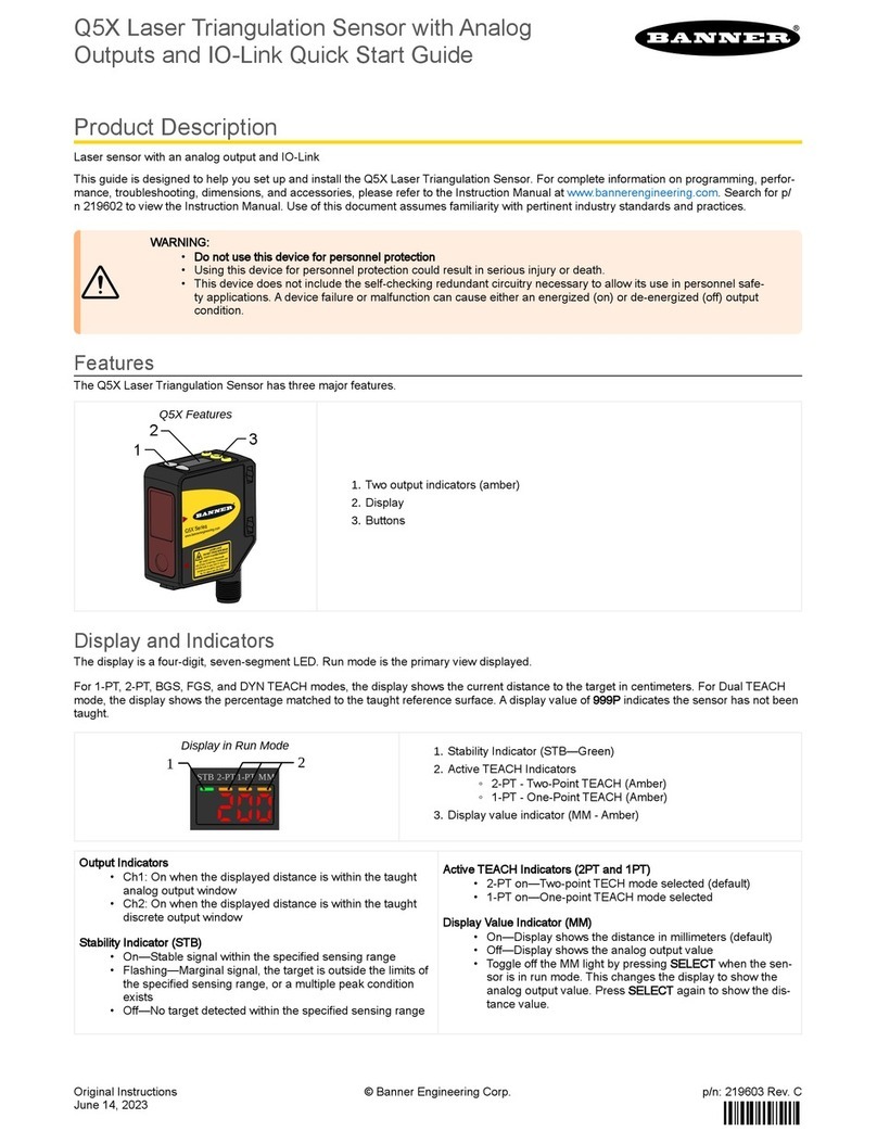
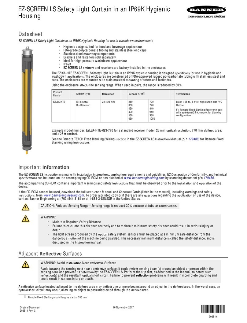
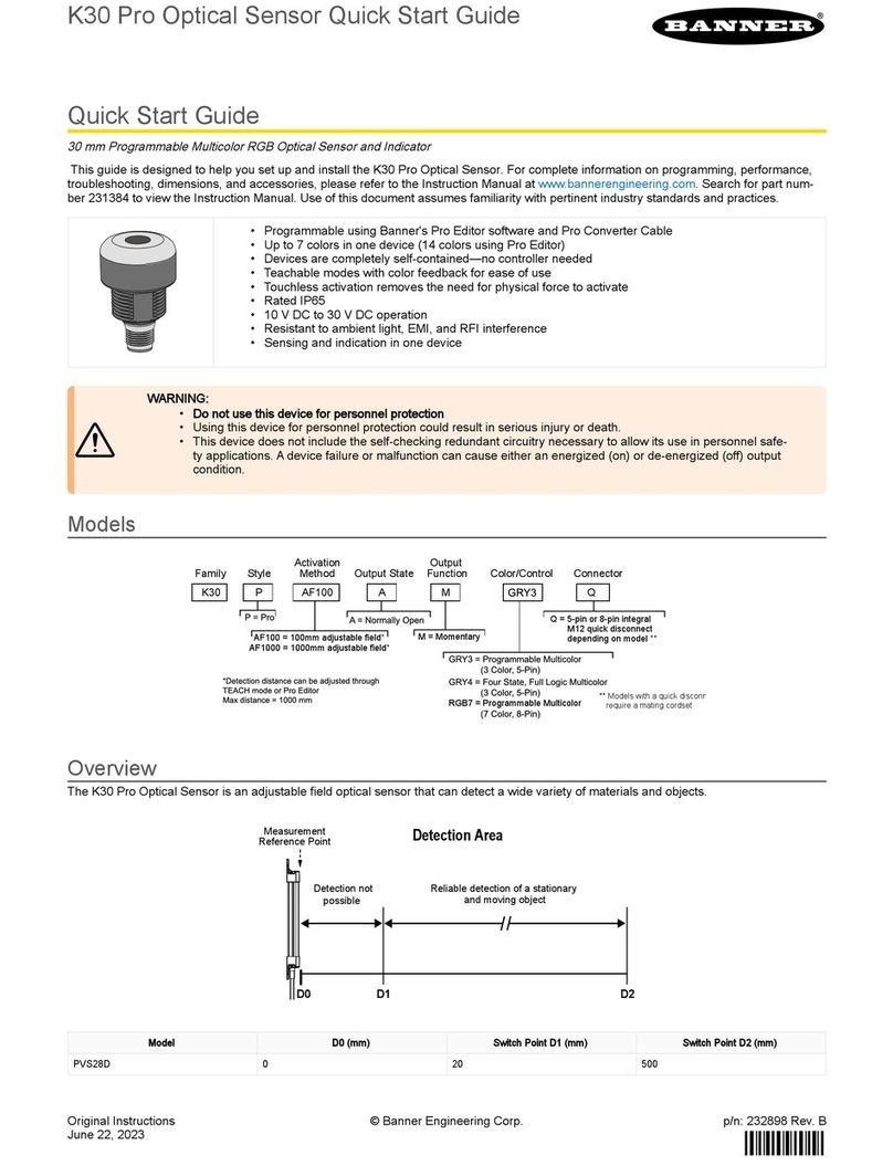
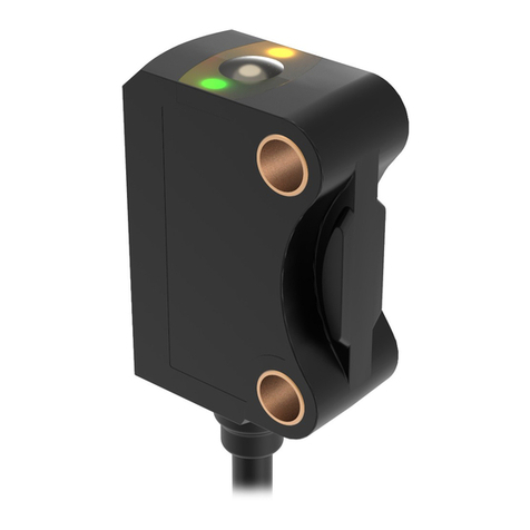
Banner Q5X User manual

Original Instructions
July 10, 2023 p/n: 218598 Rev. F
218598
Q5X Laser Triangulation Sensor with Dual
Mode and IO-Link for Jam Detection
•
•
•
Quick Start Guide
Class 2 laser CMOS sensor with dual outputs and IO-Link. Patent pending.
ThisguideisdesignedtohelpyousetupandinstalltheQ5X Laser Triangulation Sensor with Dual Mode for Jam Detection. For complete
information on programming, performance, troubleshooting, dimensions, and accessories, please refer to the Instruction Manual
atwww.bannerengineering.com.Searchforpartnumber218902toviewtheInstructionManual.Useofthisdocumentassumesfamiliarity
with pertinent industry standards and practices.
WARNING:
Do not use this device for personnel protection
Using this device for personnel protection could result in serious injury or death.
This device does not include the self-checking redundant circuitry necessary to allow its use in personnel
safety applications. A device failure or malfunction can cause either an energized (on) or de-energized (off)
output condition.
Features
TheQ5X Laser Triangulation Sensor with Dual Mode for Jam Detectionhasthreemajorfeatures.
Q5XFeatures
123
DisplayandIndicators
Thedisplayisa4-digit,7-segmentLED.Runmodeistheprimaryviewdisplayed.
For JRET, JBGS, 2-pt, BGS, FGS, and DYN TEACH modes, the display shows the current distance to the target in centimeters. For Dual
TEACHmode,thedisplayshowsthepercentagematchedtothetaughtreferencesurface.Adisplayvalueof indicatesthesensor
hasnotbeentaught.
DisplayinRunMode
STBFLO BGS
12
Output Indicator
On—Outputison
Off—Outputisoff
Stability Indicator (STB)
On—Stablesignalwithinthespecifiedsensingrange
Flashing—Marginalsignal(lowexcessgain),thetargetis
outside the limits of the specified sensing range, or a multiple
peak condition exists
Off—Notargetdetectedwithinthespecifiedsensingrange
Active TEACH Indicators (FLO, RET, BGS)
RETon—JamRetroreflectiveTEACHmodeselected(default)
BGSon—JamBackgroundSuppressionTEACHmode
selected
RETandBGSon—ForegroundsuppressionTEACHmode
selected
BGSandFLOon—BackgroundsuppressionTEACHmode
selected
FLOandRETon—DynamicTEACHmodeselected
RET,FLO,andBGSalloff—Two-pointTEACHmode
selected
RET,FLO,andBGSallon—DualTEACHmodeselected
Twooutputindicators(amber)
1.
Display
2.
Buttons
3.
StabilityIndicator(STB—Green)
1.
◦
◦
◦
Active TEACH Indicators
FLO—Amber
RET—Amber
BGS—Amber
2.
© Banner Engineering Corp.

July 10, 2023page2
Q5X Laser Triangulation Sensor with Dual Mode and IO-Link for Jam Detection
•
•
•
•
•
•
•
•
•
•
Buttons
Usethesensorbuttons(SELECT)(TEACH),(+)(CH1/CH2),and(-)(MODE)toprogramthesensor.
Button Layout
(SELECT/TEACH)
Press to select menu items in Setup mode
Press and hold for longer than 2 seconds to start the currently
selected TEACH mode (the default is Jam Retroreflective
TEACH)
(+)(CH1/CH2)
PresstonavigatethesensormenuinSetupmode
Press to change setting values; press and hold to increase
numeric values
Press and hold for longer than 2 seconds to switch between
Channel 1 and Channel 2
(-)(MODE)
Press to navigate the sensor menu in Setup mode
Press to change setting values; press and hold to decrease
numeric values
Press and hold for longer than 2 seconds to enter Setup mode
NOTE: Whennavigatingthemenu,themenuitemsloop.
Class2LaserDescriptionandSafetyInformation
ReadthefollowingsafetyinformationforproperuseofaClass2laser.
CAUTION:
Return defective units to the manufacturer.
Use of controls or adjustments or performance of procedures other than those specified herein may result in
hazardousradiationexposure.
Do not attempt to disassemble this sensor for repair. A defective unit must be returned to the manufacturer.
CAUTION:
Neverstaredirectlyintothesensorlens.
Laserlightcandamageyoureyes.
Avoid placing any mirror-like object in the beam. Never use a mirror as a retroreflective target.
For Safe Laser Use - Class 2 Lasers
Donotstareatthelaser.
Donotpointthelaserataperson’seye.
Mountopenlaserbeampathseitheraboveorbeloweyelevel,wherepractical.
Terminatethebeamemittedbythelaserproductattheendofitsusefulpath.
Class 2 lasers are lasers that emit visible radiation in the wavelength range from 400 nm to 700 nm, where eye protection is normally
afforded by aversion responses, including the blink reflex. This reaction may be expected to provide adequate protection under reasonably
foreseeableconditionsofoperation,includingtheuseofopticalinstrumentsforintrabeamviewing.
Low-power lasers are, by definition, incapable of causing eye injury within the duration of a blink (aversion response) of 0.25 seconds. They
also must emit only visible wavelengths (400 to 700 nm). Therefore, an ocular hazard may exist only if individuals overcome their natural
aversiontobrightlightandstaredirectlyintothelaserbeam.
© Banner Engineering Corp.

Q5X Laser Triangulation Sensor with Dual Mode and IO-Link for Jam Detection
July 10, 2023 page3
(1) Applying tilt to sensor may improve performance on reflective targets. The direction and magnitude of the tilt depends on the application, but a 15° tilt is often
sufficient.
Class2RedLasermodelswithmaximumrangeof2000mm:ReferenceIEC60825-1:2007
FDA (CDRH) warning label (Class 2)
LASER LIGHT
DO NOT STARE INTO BEAM
CLASS 2 LASER PRODUCT
IEC 60825-1:2007. Wavelength
640-670nm; 1.0mW max. Complies with
21 CFR 1040.10 and 1040.11 except for
deviations pursuant to Laser Notice
No. 50, dated June 24, 2007.
Output:<1.0mW
Laser wavelength:640to670nm
Pulse Duration:20µsto2ms
Installation
Sensor Orientation
Optimize detection reliability and minimum object separation performance with correct sensor-to-target orientation. To ensure reliable
detection,orientthesensorasshowninrelationtothetargettobedetected.
OptimalOrientationofTargettoSensor
See the following figures for examples of correct and incorrect sensor-to-target orientation as certain placements may pose problems for
sensingsometargets.TheQ5Xcanbeusedinthelesspreferredorientationandatsteepanglesofincidenceandstillprovidereliable
detectionperformanceduetoitshighexcessgain.Fortheminimumobjectseparationdistancerequiredforeachcase,referto"Performance
Curves" on page 12.
Orientationbyawall Orientation for a moving object Orientation for a height difference
Orientation for a color or luster difference
Horizontal
Orientation Orientation
(Optimal)
CC
Orientation for highly reflective target(1)
Reflective
Surface
(optional)
Mount the Device
Ifabracketisneeded,mountthedeviceontothebracket.
1.
© Banner Engineering Corp.

July 10, 2023page4
Q5X Laser Triangulation Sensor with Dual Mode and IO-Link for Jam Detection
Wiring Diagram
Channel2asPNPDiscreteorPFMOutput
bk (4)
bn (1)
bu (3)
wh (2)
10-30 V DC
CH1
CH2
+
–
Load
Load
Channel2asRemoteInput
bk (4)
bn (1)
bu (3)
wh (2)
10-30 V DC
CH1
CH2
+
–
Load
Remote Input
1
4
3
2
NOTE: Openleadwiresmustbeconnectedtoaterminalblock.
NOTE: TheChannel2wirefunctionandpolarityisuser-selectable.ThedefaultforthewireisPNPoutput.Refer to the
InstructionManual(p/n218902) for details regarding use as a remote input or pulse frequency modulation (PFM)
output.
Channel 1 = NPN Output, Channel 2 = NPN Output
bk (4)
bn (1)
bu (3)
wh (2)
10-30 V DC
CH1
CH2
+
–
Load
Load
Channel 1 = PNP Output, Channel 2 = PNP Output
bk (4)
bn (1)
bu (3)
wh (2)
10–30VDC
CH1
CH2
+
–
Load
Load
Channel 1 = NPN Output, Channel 2 = NPN Remote Input
bk (4)
bn (1)
bu (3)
wh (2)
10–30VDC
CH1
CH2
+
–
Load
Remote
Input
Channel 1 = PNP Output, Channel 2 = PNP Remote Input
bk (4)
bn (1)
bu (3)
wh (2)
10-30 V DC
CH1
CH2
+
–
Load
Remote Input
CleaningandMaintenance
Cleanthesensorwhensoiledandusewithcare.
Handle the sensor with care during installation and operation. Sensor windows soiled by fingerprints, dust, water, oil, etc. may create stray
light that may degrade the peak performance of the sensor. Blow the window clear using filtered, compressed air, then clean as necessary
using only water and a lint-free cloth.
ConnectingtoRSD1
ThefollowingdiagramdepictstheconnectionoftheQ5XtotheoptionalRSD1accessory.
Mount the device (or the device and the bracket) to the machine or equipment at the desired location. Do not tighten the mounting
screwsatthistime.
2.
Checkthedevicealignment.
3.
Tightenthemountingscrewstosecurethedevice(orthedeviceandthebracket)inthealignedposition.
4.
© Banner Engineering Corp.

Q5X Laser Triangulation Sensor with Dual Mode and IO-Link for Jam Detection
July 10, 2023 page5
Q5X to RSD1
MQDC-4501SS
Double Ended Sensor Pin 2 to Pin 5
MQDC-4506SS
MQDEC3-503SS
Double Ended Shielded
MQDEC3-506SS
MQDEC3-515SS
MQDEC3-530SS
MQDEC2-506
Flying Lead Shielded
MQDEC2-515
MQDEC2-530
RSD1
Q5X
Use these cordsets to connect the RSD1 to the Q5X sensor.
4-PinFemaleand5-PinMaleThreadedM12Cordset—DoubleEnded
Model Length"L1" Style Pinout
MQDC-4501SS 0.30m(0.98ft)
FemaleStraight/MaleStraight
Male
1
4
5
3
2
1=Brown
2=NotUsed
3=Blue
4=Black
5=White
MQDC-4506SS 1.83m(6.00ft)
M12 X 1.0
43.5 ± 0.5
“L1”
ø 5.9
M12 X 1.0
ø 14.5 ø 14.5
40 ± 0.5
Female
2
3
4
1
1=Brown
2=White
3=Blue
4=Black
Use these cordsets to connect the RSD1 to any PLC or IO block.
5-PinMaleThreadedand5-PinFemaleQuickDisconnectM12CordsetwithShield—DoubleEnded
Model Length"L1" Style Pinout(Male) Pinout(Female)
MQDEC3-503SS 0.91m(2.99ft)
FemaleStraight/MaleStraight
1
4
5
3
2
2
3
4
1
5
MQDEC3-506SS 1.83m(6ft)
MQDEC3-515SS 4.58m(15ft)
MQDEC3-530SS 9.2m(30.2ft)
M12 x 1
14.5
ø 5.9
14.5
“L1”
47.4 47.4
M12 x 1
1=Brown
2=White
3=Blue
4=Black
5=Gray
© Banner Engineering Corp.

July 10, 2023page6
Q5X Laser Triangulation Sensor with Dual Mode and IO-Link for Jam Detection
5-PinThreadedM12CordsetswithShield—SingleEnded
Model Length Style Dimensions Pinout(Female)
MQDEC2-506 2m(6.56ft)
Straight
44 Typ.
ø 14.5
M12 x 1
2
3
4
1
5
1=Brown
2=White
3=Blue
4=Black
5=Gray
MQDEC2-515 5m(16.4ft)
MQDEC2-530 9m(29.5ft)
MQDEC2-550 15m(49.2ft)
MQDEC2-575 23m(75.44ft)
MQDEC2-5100 30.5m(100ft)
MQDEC2-506RA 2m(6.56ft)
Right-Angle
32 Typ.
[1.26"]
30 Typ.
[1.18"]
ø 14.5 [0.57"]
M12 x 1
MQDEC2-515RA 5m(16.4ft)
MQDEC2-530RA 9m(29.5ft)
MQDEC2-550RA 15m(49.2ft)
MQDEC2-575RA 23m(75.44ft)
MQDEC2-5100RA 31m(101.68ft)
Button Map from RSD1 to Sensor
The sensor may be optionally connected to the Banner RSD1 remote display accessory. Refer to this table for the RSD1 button association
withyoursensor.
Button association between the RSD1 and the Q4X/Q5X sensors
Device UpButton DownButton EnterButton EscapeButton
RSD1
Q4XandQ5X
N/A
SensorProgramming
Programthesensorusingthebuttonsonthesensorortheremoteinput(limitedprogrammingoptions).
In addition to programming the sensor, use the remote input to disable the buttons for security, preventing unauthorized or accidental
programmingchanges.SeetheInstructionManual,p/n218902formoreinformation.
Setup Mode
AccessSetupmodeandthesensormenufromRunmodebypressingandholdingMODEforlongerthan2seconds.
Use+and-tonavigatethroughthemenu.PressSELECTtoselectamenuoptionandaccessthesubmenus.Use+and-tonavigate
throughthesubmenus.PressSELECTtoselectasubmenuoptionandreturntothetopmenu,orpressandholdSELECTforlongerthan2
secondstoselectasubmenuoptionandreturnimmediatelytoRunmode.
ToexitSetupmodeandreturntoRunmode,navigatetoEndandpressSELECT.
NOTE: Thenumberthatfollowsamenuoption,forexampletch1, indicates the channel that is selected. For menu
items without a number (excluding submenu items), these menu options are only available from Channel 1 and the
settingsapplytobothchannels.
© Banner Engineering Corp.

Q5X Laser Triangulation Sensor with Dual Mode and IO-Link for Jam Detection
July 10, 2023 page7
Sensor Menu Map—Channel1
© Banner Engineering Corp.

July 10, 2023page8
Q5X Laser Triangulation Sensor with Dual Mode and IO-Link for Jam Detection
SensorMenuMap—Channel2
© Banner Engineering Corp.

Q5X Laser Triangulation Sensor with Dual Mode and IO-Link for Jam Detection
July 10, 2023 page9
•
•
•
•
•
•
•
BasicTEACHInstructions
UsethefollowinginstructionstoteachtheQ5Xsensor.Theinstructionsprovidedonthesensordisplayvarydependingonthetypeof
TEACHmodeselected.Jam Retroreflective TEACH is the default TEACH mode on CH1, and Jam Background Suppression TEACH is the
default TEACH mode on CH2.
See the Instruction Manual for detailed instructions and other available TEACH modes. The TEACH modes include:
Two-pointstaticbackgroundsuppression —Two-pointTEACHsetsasingleswitchpoint.The sensor sets the switch point
between two taught target distances, relative to the shifted origin location.
Dynamicbackgroundsuppression —Dynamic TEACH sets a single switch point during machine run conditions.The sensor
takes multiple samples and the switch point is set between the minimum and the maximum sampled distances.
One-pointwindow(foregroundsuppression) —One-point window sets a window (two switch points) centered around the
taught target distance.
One-pointbackgroundsuppression —One-point background suppression sets a single switch point in front of the taught
target distance. Objects beyond the taught switch point are ignored.
Dualintensity+distance —Dualmoderecordsthedistanceandamountoflightreceivedfromthereferencesurface.
See"Dual Mode Reference Surface Considerations" on page 12formoreinformationaboutselectingareferencesurface.The
output switches when an object passing between the sensor and the reference surface changes the perceived distance or amount of
returnedlight.
Jamretroreflective —JamretroreflectiveTEACHmodeisanextensionofDualModeoptimizedforjamdetectionwhena
background is present. This mode sets a window with two switch points centered around the taught target distance. Measurements
with valid intensity inside this window are qualified as not jammed. An independent jam range (RNG) value is set which defines the
minimum movement required, which in combination with an automatically determined intensity threshold, determines that an object
ismoving(notjammed).ALossofSignalfortheuser-definedtimeistreatedasajam.
Jambackgroundsuppression —JambackgroundsuppressionTEACHmodeisanextensionofDualModeoptimizedforjam
detection when no background is present. This mode sets a background suppression point in front of the taught target distance.
Measurements with a valid intensity inside this window are qualified as not jammed. An independent jam range (RNG) value is set
by the user which defines the minimum movement required, which in combination with an automatically determined intensity
threshold,determinesthatanobjectismoving(notjammed).ALossofSignalconditionisnottreatedasajam.
Manual Adjustments
Manuallyadjustthesensorswitchpointusingthe and buttons.
NOTE: When FGS TEACH mode is selected, manual adjustment moves both sides of the symmetrical threshold
window simultaneously, expanding and collapsing the window size. Manual adjustment does not move the center point
ofthewindow.
NOTE: When Dual TEACH mode is selected, after the TEACH process is completed, use the manual adjustment to
adjust the sensitivity of the thresholds around the taught reference point. The taught reference point is a combination of
the measured distance and returned signal intensity from the reference target. Manual adjustment does not move the
taughtreferencepoint,butpressing increasesthesensitivity,andpressing decreasesthesensitivity.Whenre-
positioningthesensororchangingthereferencetarget,re-teachthesensor.
RNG
WhenthesensorisinJRETorJBGSTEACHmode,usethe or buttonstoadjusttheRNGvalue.TheRNGvaluedefinesthe
minimum movement the sensor must see to determine that an object is moving (not jammed). For most applications, the default setting
isacceptable.
PressandholdTEACHforlongerthan2secondstostarttheselectedTEACHmode.
1.
Presentthetarget.
2.
PressTEACHtoteachthetarget.Thetargetistaughtandthesensorwaitsforthesecondtarget,ifrequiredbytheselectedTEACH
mode,orreturnstoRunmode.
3.
CompletethesestepsonlyifitisrequiredfortheselectedTEACHmode.
4.
Presentthesecondtarget.
a.
PressTEACHtoteachthetarget.ThetargetistaughtandthesensorreturnstoRunmode.
b.
FromRunmode,presseither or onetime.Theselectedchanneldisplaysbriefly,thenthecurrentsettingvalueflashes
slowly.
1.
Press toincreasethesettingor todecreasethesetting.After1secondofinactivity,thenewsettingvalueflashesrapidly,
thenewsettingisaccepted,andthesensorreturnstoRunmode.
2.
© Banner Engineering Corp.

July 10, 2023page10
Q5X Laser Triangulation Sensor with Dual Mode and IO-Link for Jam Detection
•
•
•
Locking and Unlocking the Sensor Buttons
Usethelockandunlockfeaturetopreventunauthorizedoraccidentalprogrammingchanges.
Three settings are available:
—Thesensorisunlockedandallsettingscanbemodified(default).
—Thesensorislockedandnochangescanbemade.
—Theswitchpointvaluecanbechangedbyteachingormanualadjustment,butnosensorsettingscanbechangedthrough
themenu.
WheninLocmode,Locdisplayswhenthe(SELECT)(TEACH)buttonispressed.Theswitchpointdisplayswhen(+)(CH1/CH2)or(-)
(MODE)arepressed,butLocdisplaysifthebuttonsarepressedandheld.
Whenin0Locmode,Locdisplayswhen(+)(CH1/CH2)or(-)(MODE)arepressedandheld.Toaccessthemanualadjustoptions,briefly
pressandrelease(+)(CH1/CH2)or(-)(MODE).ToenterTEACHmode,pressthe(SELECT)(TEACH)buttonandholdforlongerthan2
seconds.
ToenterLocmode,hold+andpress-fourtimes.Toenter0Locmode,hold+andpress-seventimes.Holding+andpressing-fourtimes
unlocksthesensorfromeitherlockmodeandthesensordisplaysuLoc.
Specifications
Sensing Beam
Visible red, Class 2 laser, 650 nm
Supply Voltage (Vcc)
10 to 30 V DC (Class 2 supply) (10% max ripple within limits)
Power and Current Consumption, exclusive of load
< 1 W
Sensing Range
95mmto2000mm(3.74into78.74in)
Output Configuration
Channel1:Push/pulloutput,configurablePNPorNPNoutput
Channel 2: Multi-function remote input/output, configurable
PNPorNPN,orpulsefrequencymodulatedoutput
Output Rating
Current rating: 50 mA maximum
Blackwirespecificationsperconfiguration
Push/Pull
OutputHigh: ≥Vsupply-2.5V
OutputLow: ≤2.5V
PNP
OutputHigh: ≥Vsupply-2.5V
OutputLow: ≤1V(loads≤1MegΩ)
NPN
OutputHigh: ≥Vsupply-2.5V(loads≤50kΩ)
OutputLow: ≤2.5V
Whitewirespecificationsperconfiguration
PNP
OutputHigh: ≥Vsupply-2.5V
OutputLow: ≤2.5V(loads≤70kΩ)
NPN
OutputHigh: ≥Vsupply-2.5V(loads≤70kΩ)
OutputLow: ≤2.5V
Beam Spot Size
x
yBeam
Spot
Pattern
Distance(mm) Size(x×y)(mm)
100 2.6×1.5
1000 4.2×2.5
2000 6×3.6
Beamspotsizeiscalculatedas1.6timestheD4σmeasured
value
Required Overcurrent Protection
WARNING: Electrical connections must
be made by qualified personnel in
accordance with local and national
electricalcodesandregulations.
Overcurrent protection is required to be provided by end
productapplicationperthesuppliedtable.
Overcurrent protection may be provided with external fusing
or via Current Limiting, Class 2 Power Supply.
Supply wiring leads < 24 AWG shall not be spliced.
For additional product support, go
towww.bannerengineering.com.
Supply
Wiring
(AWG)
Required Overcurrent
Protection (A)
Supply
Wiring
(AWG)
Required Overcurrent
Protection (A)
20 5.0 26 1.0
22 3.0 28 0.8
24 1.0 30 0.5
© Banner Engineering Corp.

Q5X Laser Triangulation Sensor with Dual Mode and IO-Link for Jam Detection
July 10, 2023 page11
(1) Standard excess gain available in 15, 25, and 50 ms response speeds; standard excess gain provides increase noise immunity.
Boresighting
±43mmat2000mm
Response Speed
User selectable: 15, 25, or 50 ms
Delay at Power Up
< 2.5 s
Maximum Torque
Sidemounting:1N·m(9in·lbs)
Ambient Light Immunity
Up to 5000 lux at 1000 mm
Up to 2000 lux at 2000 mm
Connector
Integral 4-pin M12 male quick-disconnect connector
Construction
Housing: ABS
Lens cover: PMMA acrylic
Lightpipe and display window: polycarbonate
Temperature Effect (Typical)
< 0.5 mm/°C at < 500 mm
<1.0mm/°Cat<1000mm
< 2.0 mm/°C at < 2000 mm
Discrete Output Distance Repeatability
Distance(mm) Repeatability
95to300 ±0.5mm
300to1000 ±0.25%
1000to2000 ±0.5%
Supply Protection Circuitry
Protected against reverse polarity and transient overvoltages
Remote Input
Allowable Input Voltage Range: 0 to Vsupply
ActiveHigh(internalweakpull-down):Highstate>(Vsupply–
2.25 V) at 2 mA maximum
Active Low (internal weak pull-up): Low state < 2.25 V at 2 mA
maximum
IO-Link Interface
IO Link Revision V1.1
Supports Smart Sensor Profile: Yes
Baud Rate: 38400 bps
ProcessDataInLength:32bits
Process Data Out Length: 8 bits
Minimum Cycle Time: 3.6 ms
IODD files: Provides all programming options of the display,
plus additional functionality.
Application Note
For optimum performance, allow 10 minutes for the sensor to
warm up
Environmental Rating
IP67perIEC60529
Vibration
MIL-STD-202G, Method 201A (Vibration: 10 Hz to 55 Hz, 0.06
inch (1.52 mm) double amplitude, 2 hours each along X, Y
and Z axes), with device operating
Shock
MIL-STD-202G, Method 213B, Condition I (100G 6x along X,
Y, and Z axes, 18 shocks), with device operating
Operating Conditions
–10°Cto+50°C(+14°Fto+122°F)
35% to 95% relative humidity
Storage Temperature
–25°Cto+70°C(–13°Fto+158°F)
Certifications
Banner Engineering BVParkLane,
Culliganlaan 2F bus 3, 1831 Diegem,
BELGIUM
Turck Banner LTDBlenheimHouse,
Blenheim Court, Wickford, Essex SS11
8YT, Great Britain
Class 2 power
ULEnvironmentalRating:Type1
Advanced Capabilities
Excess Gain
ExcessGainUsinga90%WhiteCard(1)
ResponseSpeed(ms) at100mm at500mm at1000mm at2000mm
15 725(225) 250(75) 70(25) 15(6)
25 1250(800) 450(250) 125(70) 30(15)
50 2500(1250) 900(450) 250(125) 60(30)
FCC Part 15 Class A
This equipment has been tested and found to comply with the limits for a Class A digital device, pursuant to part 15 of the FCC Rules. These
limits are designed to provide reasonable protection against harmful interference when the equipment is operated in a commercial
environment. This equipment generates, uses, and can radiate radio frequency energy and, if not installed and used in accordance with the
instruction manual, may cause harmful interference to radio communications. Operation of this equipment in a residential area is likely to
causeharmfulinterferenceinwhichcasetheuserwillberequiredtocorrecttheinterferenceathisownexpense.
© Banner Engineering Corp.

July 10, 2023page12
Q5X Laser Triangulation Sensor with Dual Mode and IO-Link for Jam Detection
Industry Canada ICES-003(A)
This device complies with CAN ICES-3 (A)/NMB-3(A). Operation is subject to the following two conditions: 1) This device may not cause
harmfulinterference;and2)Thisdevicemustacceptanyinterferencereceived,includinginterferencethatmaycauseundesiredoperation.
Cet appareil est conforme à la norme NMB-3(A). Le fonctionnement est soumis aux deux conditions suivantes : (1) ce dispositif ne peut pas
occasionner d'interférences, et (2) il doit tolérer toute interférence, y compris celles susceptibles de provoquer un fonctionnement non
souhaité du dispositif.
PerformanceCurves
Minimum Object Separation Distance (90% to 6% reflectance)
Minimum Separation Target to Background (mm)
Dimension
Distance to Target (mm)
Dimension X
0
10
20
30
40
50
60
70
80
0200 400 600 800 1000 1200 1400 1600 1800 2000
Switch Point
Distance
Background
X
Y
Dual Mode Reference Surface Considerations
Optimize reliable detection by applying these principles when selecting your reference surface, positioning your sensor relative to the
referencesurface,andpresentingyourtarget.
TherobustdetectioncapabilitiesoftheQ5Xallowssuccessfuldetectionevenundernon-idealconditionsinmanycases.Typicalreference
surfaces are metal machine frames, conveyor side rails, or mounted plastic targets. Contact Banner Engineering if you require assistance
settingupastablereferencesurfaceinyourapplication.
Fordetailedinstructionsfordetectingclearortransparentobjects,refertotheInstructionManual,p/n218902.
◦
◦
◦
Selectareferencesurfacewiththesecharacteristicswherepossible:
Matteordiffusesurfacefinish
Fixedsurfacewithnovibration
Drysurfacewithnobuild-upofoil,water,ordust
1.
Positionthereferencesurfacebetween200mm(20cm)andthemaximumsensingrange.
2.
Positionthetargettobedetectedasclosetothesensoraspossible,andasfarawayfromthereferencesurfaceaspossible.
3.
Anglethesensingbeamrelativetothetargetandrelativetothereferencesurface10degreesormore.
4.
© Banner Engineering Corp.
Q5X Laser Triangulation Sensor with Dual Mode and IO-Link for Jam Detection
July 10, 2023 page13
BannerEngineeringCorp.LimitedWarranty
Banner Engineering Corp. warrants its products to be free from defects in material and workmanship for one year following the date of shipment. Banner Engineering Corp. will repair or replace, free
of charge, any product of its manufacture which, at the time it is returned to the factory, is found to have been defective during the warranty period. This warranty does not cover damage or liability for
misuse,abuse,ortheimproperapplicationorinstallationoftheBannerproduct.
THIS LIMITED WARRANTY IS EXCLUSIVEAND IN LIEU OF ALL OTHER WARRANTIES WHETHER EXPRESS OR IMPLIED (INCLUDING, WITHOUT LIMITATION, ANY WARRANTY OF
MERCHANTABILITY OR FITNESS FOR APARTICULAR PURPOSE), AND WHETHERARISING UNDER COURSE OF PERFORMANCE, COURSE OF DEALING OR TRADE USAGE.
ThisWarrantyisexclusiveandlimitedtorepairor,atthediscretionofBannerEngineeringCorp.,replacement.INNOEVENTSHALLBANNERENGINEERINGCORP.BELIABLETOBUYEROR
ANY OTHER PERSON OR ENTITY FORANY EXTRACOSTS, EXPENSES, LOSSES, LOSS OF PROFITS, OR ANY INCIDENTAL, CONSEQUENTIAL OR SPECIAL DAMAGES RESULTING
FROM ANY PRODUCT DEFECT OR FROM THE USE OR INABILITYTO USE THE PRODUCT, WHETHER ARISING IN CONTRACT OR WARRANTY, STATUTE, TORT, STRICT LIABILITY,
NEGLIGENCE, OR OTHERWISE.
Banner Engineering Corp. reserves the right to change, modify or improve the design of the product without assuming any obligations or liabilities relating to any product previously manufactured by
Banner Engineering Corp. Any misuse, abuse, or improper application or installation of this product or use of the product for personal protection applications when the product is identified as not
intended for such purposes will void the product warranty. Any modifications to this product without prior express approval by Banner Engineering Corp will void the product warranties.All
specifications published in this document are subject to change; Banner reserves the right to modify product specifications or update documentation at any time. Specifications and product
informationinEnglishsupersedethatwhichisprovidedinanyotherlanguage.Forthemostrecentversionofanydocumentation,referto:www.bannerengineering.com.
Forpatentinformation,seewww.bannerengineering.com/patents.
© Banner Engineering Corp.
Other manuals for Q5X
12
Table of contents
Other Banner Security Sensor manuals

Banner
Banner PVS28 Series User manual

Banner
Banner LTF User manual

Banner
Banner Q5X User manual

Banner
Banner VS8LEJ User manual

Banner
Banner EZ-SCREEN User manual

Banner
Banner K30 Pro User manual

Banner
Banner SX5 User manual

Banner
Banner LS2e30-300Q8 User manual

Banner
Banner LTF Series User manual

Banner
Banner EZ-SCREEN SLSP14-450Q88 User manual
Popular Security Sensor manuals by other brands

Haws
Haws 7500 Installation, operation & maintenance instructions

Wohler
Wohler GS 220 manual

PCB Piezotronics
PCB Piezotronics IMI SENSORS X649A03 Installation and operating manual

ICP DAS USA
ICP DAS USA ISN-101 user manual

EVERSPRING
EVERSPRING ST802 user manual

Agilent Technologies
Agilent Technologies G1315B user manual