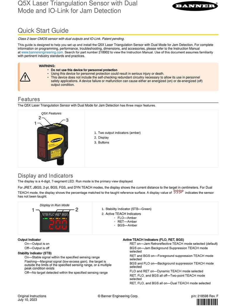
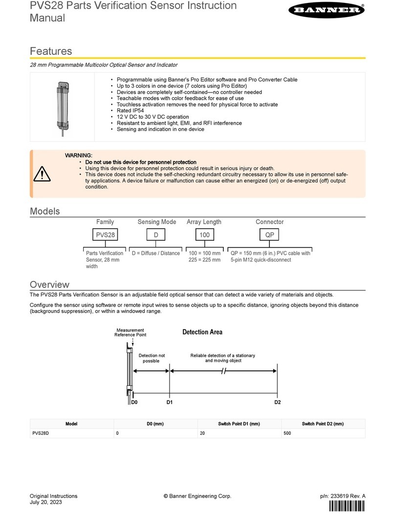
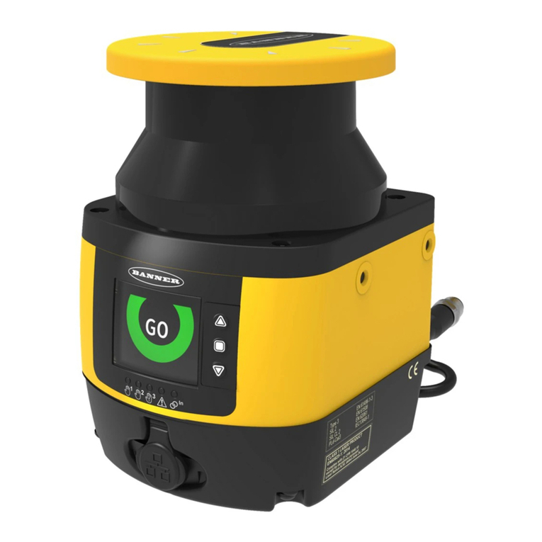
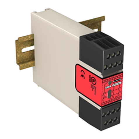
Banner L-GAGE LTF12 User manual

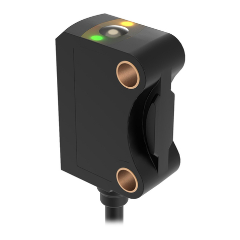
LTF Time of Flight Laser Distance Sensor
with IO-Link Instruction Manual
Original Instructions
p/n: 195393 Rev. I
June 22, 2023
© Banner Engineering Corp. All rights reserved.

2
Contents
Contents.................................................................................................................................. 2
Chapter 1 Quick Start Guide Product Description
Models ........................................................................................................................................................................................................ 5
Overview....................................................................................................................................................................................................... 5
Features and Indicators ......................................................................................................................................................................... 6
Display ................................................................................................................................................................................................... 6
Buttons and Icons .................................................................................................................................................................................. 6
Laser Description and Safety Information .................................................................................................................................................... 7
Class 2 Laser Models ............................................................................................................................................................................ 7
Chapter 2 Sensor Installation
Mount the Device.......................................................................................................................................................................................... 9
WiringDiagrams .......................................................................................................................................................................................... 9
ConnectingtoRSD1.................................................................................................................................................................................. 10
Chapter 3 Sensor Programming
QuickMenu ............................................................................................................................................................................................... 13
LTFSensorMenu(MENU) ......................................................................................................................................................................... 14
RemoteInput ............................................................................................................................................................................................ 14
LockingandUnlockingtheSensor ........................................................................................................................................................... 16
Discrete Output Menu (D_OUT)(Dx_OUT)................................................................................................................................................. 17
Two-Point TEACH................................................................................................................................................................................ 17
Midpoint TEACH .................................................................................................................................................................................. 19
AdjustSwitchPointOne .................................................................................................................................................................... 21
AdjustSwitchPointTwo..................................................................................................................................................................... 21
TEACHSwitchPoint........................................................................................................................................................................... 21
AdjustSwitchPoint ............................................................................................................................................................................ 22
Mode .................................................................................................................................................................................................... 23
SwitchPointReference(SPtRef)........................................................................................................................................................ 24
SwitchPointTEACHOffset ............................................................................................................................................................... 25
SwitchPointHysteresis ...................................................................................................................................................................... 25
Timer.................................................................................................................................................................................................... 26
Polarity ................................................................................................................................................................................................. 27
Input Menu (INPUT) ................................................................................................................................................................................... 27
InputType .......................................................................................................................................................................................... 27
InputActive ........................................................................................................................................................................................ 28
Measure Menu (MEASURE) ...................................................................................................................................................................... 28
Speed.................................................................................................................................................................................................. 28
Display Menu (DISPLAY)............................................................................................................................................................................ 29
Units................................................................................................................................................................................................... 29
ZeroandShift ..................................................................................................................................................................................... 30
View .................................................................................................................................................................................................... 31
Sleep.................................................................................................................................................................................................. 32
Information Menu (INFO)............................................................................................................................................................................ 32
Reset Menu (RESET)................................................................................................................................................................................. 32
Factory Default Settings ...................................................................................................................................................................... 33
Chapter 4 Sync Master/Slave ............................................................................................ 35
Chapter 5 Additional Remote TEACH Procedures
TEACHBothDiscreteOutputSwitchPointsTogether ............................................................................................................................ 37
TEACHBothDiscreteOutputMidpointsTogether.................................................................................................................................... 38
Chapter 6 Product Support and Maintenance
Sensor Menu Full Map ............................................................................................................................................................................... 40
Troubleshooting ........................................................................................................................................................................................ 41
Specifications ............................................................................................................................................................................................. 41
Repeatability Performance .................................................................................................................................................................. 43
Dimensions ......................................................................................................................................................................................... 44

3
Accessories ................................................................................................................................................................................................ 45
Cordsets............................................................................................................................................................................................... 45
Brackets .............................................................................................................................................................................................. 46
RSD1 Remote Display......................................................................................................................................................................... 46
BannerEngineeringCorpLimitedWarranty.............................................................................................................................................. 47
.............................................................................................................................................................................................................. 47

Blank page
4

June 22, 2023
LTF Time Of Flight Laser Distance Sensor With IO-Link Instruction Manual
5
•
•
•
•
•
•
•
Chapter Contents
Models............................................................................................................................................................................................................... 5
Overview ............................................................................................................................................................................................................. 5
Laser Description and Safety Information ........................................................................................................................................................... 7
Laser distance sensor with dual discrete (switched) outputs and IO-Link.
Highperformancetimeofflightmeasurement
Upto24mrange
Reliablydetectschallengingtargets
Fastsetupwithintuitiveinterface
WARNING:
Do not use this device for personnel protection
Using this device for personnel protection could result in serious injury or death.
This device does not include the self-checking redundant circuitry necessary to allow its use in
personnel safety applications. A device failure or malfunction can cause either an energized (on)
or de-energized (off) output condition.
Models
Family Connector
Q = Rotatable M12/Euro QD
QP = PVC M12/Euro Pigtail QD
QD models require mating cordset
Q
Range (m)
12
LTF
12
Laser
Class
C2
C2 = Class 2 LD = Laser diffuse
KLD
Output
Sensing
Mode
K= (2) NPN/PNP discrete
with I/O Link
= 12 m
24 = 24 m
Overview
TheLTF Time of Flight Laser Distance Sensor with IO-Linkisdesignedforprecise,long-distancemeasurements.A2-line
LCDshowsthereal-timedistancemeasurement,ineithermillimetersorinches,whenthesensorisinRunmode.
See
Factory Defaults
foralistofsensordefaultsettings.
Modelswithcurrentorvoltageanalogoutputsareavailable.
Quick Start Guide Product Description
Chapter 1
© Banner Engineering Corp.

June 22, 2023
LTF Time Of Flight Laser Distance Sensor With IO-Link Instruction Manual
6
•
•
•
•
•
•
•
•
Features and Indicators
Features
Display
Push Buttons
ThreeLEDindicatorsprovideongoingindicationofthesensing
status.
PowerLEDIndicator
SolidGreen=Normaloperation,powerOnandlaserOn
Flashing Green (1 Hz) = Power On and laser Off (laser enable
mode)
DiscreteOutputLEDIndicators
SolidAmber=DiscreteOutputisOn
Off=DiscreteOutputisOff
Display
showninRunMode
The display is a 2-line, 8-character LCD. The main screen is
the Run mode screen, which shows the real-time distance
measurement.
Buttons and Icons
UsethesensorbuttonsDown,Up,Enter,andEscapetoprogramthesensorandtoaccesssensorinformation.
Down and Up Buttons
PressDownandUpto:
AccesstheQuickMenufromRunmode
Navigatethemenusystems
Changeprogrammingsettings
Changeindividualdigitvaluesindistancebasedsettings
Whennavigatingthemenusystems,themenuitemsloop.
Enter Button
PressEnterto:
AccesstheSensorMenufromRunmode
Accessthesubmenus
Moverightonedigitindistancebasedsettings
Savechanges
IntheSensorMenu,acheckmark inthelowerrightcornerofthedisplayindicatesthatpressingEn-
teraccessesasubmenu.
PressEntertosavechanges.Newvaluesflashrapidlyandthesensorreturnstotheparentmenu.
Continued on page 7
© Banner Engineering Corp.

June 22, 2023
LTF Time Of Flight Laser Distance Sensor With IO-Link Instruction Manual
7
•
•
•
•
•
•
•
•
•
•
•
•
Continued from page 6
Escape Button
PressEscapeto:
Leavethecurrentmenuandreturntotheparentmenu
ReturntoRunmodefromtheQuickMenu
IMPORTANT: PressingEscapediscardsanyunsavedprogrammingchanges.
IntheSensorMenu,areturnarrowintheupperleftcornerofthedisplayindicatesthatpressingEscapere-
turnstotheparentmenu.
PressandholdEscapefor2secondstoreturntoRunmodefromanymenuorremoteteach.
Alocksymboldisplaysintheupperleftcornerofthedisplaytoindicatewhenthesensorislocked.
Laser Description and Safety Information
CAUTION:
Return defective units to the manufacturer.
Use of controls or adjustments or performance of procedures other than those specified herein
mayresultinhazardousradiationexposure.
Donotattempttodisassemblethissensorforrepair.Adefectiveunitmustbereturnedtotheman-
ufacturer.
Class 2 Laser Models
CAUTION:
Never stare directly into the sensor lens.
Laserlightcandamageyoureyes.
Avoid placing any mirror-like object in the beam. Never use a mirror as a retroreflective target.
For Safe Laser Use - Class 2 Lasers
Donotstareatthelaser.
Donotpointthelaserataperson’seye.
Mountopenlaserbeampathseitheraboveorbeloweyelevel,where
practical.
Terminate the beam emitted by the laser product at the end of its useful
path.
Reference IEC 60825-1:2007, Section 8.2.
Continued on page 8
© Banner Engineering Corp.

June 22, 2023
LTF Time Of Flight Laser Distance Sensor With IO-Link Instruction Manual
8
Continued from page 7
Class 2 Lasers
Class 2 lasers are lasers that emit visible radiation in the wavelength range from
400nmto700nm,whereeyeprotectionisnormallyaffordedbyaversionre
sponses,includingtheblinkreflex.Thisreactionmaybeexpectedtoprovideade
quate protection under reasonably foreseeable conditions of operation, including
theuseofopticalinstrumentsforintrabeamviewing.
FDA (CDRH) warning label (Class 2)
Class 2 Laser Safety Notes
Lowpowerlasersare,bydefinition,incapableofcausingeyeinjurywithinthedu
ration of a blink (aversion response) of 0.25 seconds. They also must emit only
visible wavelengths (400 to 700 nm). Therefore, an ocular hazard may exist only
if individuals overcome their natural aversion to bright light and stare directly into
thelaserbeam.
© Banner Engineering Corp.

June 22, 2023
LTF Time Of Flight Laser Distance Sensor With IO-Link Instruction Manual
9
Chapter Contents
Mount the Device ................................................................................................................................................................................................ 9
WiringDiagrams................................................................................................................................................................................................. 9
ConnectingtoRSD1......................................................................................................................................................................................... 10
NOTE: Handlethesensorwithcareduringinstallationandoperation.Sensorwindowssoiledbyfinger-
prints, dust, water, oil, etc. may create stray light that may degrade the peak performance of the sensor.
Blowthewindowclearusingfiltered,compressedair,thencleanasnecessaryusing70%isopropylalco-
hol and cotton swabs or water and a soft cloth.
Mount the Device
WiringDiagrams
IO-Link Models
shield
+
12–30VDC
D1_Out / IO-Link
D2_Out
Input
–
* User-configurable PNP/NPN setting
bu (3)
bn (1)
wh (2)
bk (4)
gy (5)
NPN
or
Load
Load
Key
2
3
4
1
5
1=Brown
2=White
3=Blue
4=Black
5=Gray
SensorInstallation
Chapter 2
Ifabracketisneeded,mountthedeviceontothebracket.
1.
Mount the device (or the device and the bracket) to the machine or equipment at the desired location. Do not tighten
themountingscrewsatthistime.
2.
Checkthedevicealignment.
3.
Tightenthemountingscrewstosecurethedevice(orthedeviceandthebracket)inthealignedposition.
4.
© Banner Engineering Corp.

June 22, 2023
LTF Time Of Flight Laser Distance Sensor With IO-Link Instruction Manual
10
ConnectingtoRSD1
ThefollowingdiagramdepictstheconnectionoftheLTFtotheoptionalRSD1accessory.
LTF to RSD1
MQDEC3-503SS
Double Ended Shielded
MQDEC3-506SS
MQDEC3-515SS
MQDEC3-530SS
MQDEC2-506
Flying Lead Shielded
MQDEC2-515
MQDEC2-530
RSD1
LTF
MQDEC3-503SS
Double Ended Shielded
MQDEC3-506SS
MQDEC3-515SS
MQDEC3-530SS
UsethesecordsetstoconnecttheRSD1totheLTFsensorortootherdevices,suchasPLCinputs,IO-Linkmasters,orcon-
trol systems.
5-PinMaleThreadedand5-PinFemaleQuickDisconnectM12CordsetwithShield—DoubleEnded
Model Length"L1" Style Pinout(Male) Pinout(Female)
MQDEC3-503SS 0.91m(2.99ft)
FemaleStraight/MaleStraight
1
4
5
3
2
2
3
4
1
5
MQDEC3-506SS 1.83m(6ft)
MQDEC3-515SS 4.58m(15ft)
MQDEC3-530SS 9.2m(30.2ft)
M12 x 1
14.5
ø 5.9
14.5
“L1”
47.4 47.4
M12 x 1
1=Brown
2=White
3=Blue
4=Black
5=Gray
5-PinThreadedM12CordsetswithShield—SingleEnded
Model Length Style Dimensions Pinout(Female)
MQDEC2-506 2m(6.56ft)
Straight
44 Typ.
ø 14.5
M12 x 1
2
3
4
1
5
1=Brown
2=White
3=Blue
4=Black
5=Gray
MQDEC2-515 5m(16.4ft)
MQDEC2-530 9m(29.5ft)
MQDEC2-550 15m(49.2ft)
MQDEC2-575 23m(75.44ft)
MQDEC2-5100 30.5m(100ft)
Continued on page 11
© Banner Engineering Corp.

June 22, 2023
LTF Time Of Flight Laser Distance Sensor With IO-Link Instruction Manual
11
Continued from page 10
5-PinThreadedM12CordsetswithShield—SingleEnded
Model Length Style Dimensions Pinout(Female)
MQDEC2-506RA 2m(6.56ft)
Right-Angle
32 Typ.
[1.26"]
30 Typ.
[1.18"]
ø 14.5 [0.57"]
M12 x 1
MQDEC2-515RA 5m(16.4ft)
MQDEC2-530RA 9m(29.5ft)
MQDEC2-550RA 15m(49.2ft)
MQDEC2-575RA 23m(75.44ft)
MQDEC2-5100RA 31m(101.68ft)
© Banner Engineering Corp.

Blank page
12

June 22, 2023
LTF Time Of Flight Laser Distance Sensor With IO-Link Instruction Manual
13
Chapter Contents
QuickMenu ...................................................................................................................................................................................................... 13
LTFSensorMenu(MENU)................................................................................................................................................................................ 14
RemoteInput................................................................................................................................................................................................... 14
LockingandUnlockingtheSensor.................................................................................................................................................................. 16
Discrete Output Menu (D_OUT)(Dx_OUT) ....................................................................................................................................................... 17
Input Menu (INPUT) .......................................................................................................................................................................................... 27
Measure Menu (MEASURE) ............................................................................................................................................................................. 28
Display Menu (DISPLAY) .................................................................................................................................................................................. 29
Information Menu (INFO) .................................................................................................................................................................................. 32
Reset Menu (RESET)........................................................................................................................................................................................ 32
Programthesensorusingthebuttonsonthesensorortheremoteinput(limitedprogrammingoptions).
FromRunmode,usethebuttonstoaccesstheQuickMenuandtheSensorMenu.See"QuickMenu" on page
13and"LTFSensorMenu(MENU)" on page 14formoreinformationontheoptionsavailablefromeachmenu.ForTEACH
options,followtheTEACHinstructions.
In addition to programming the sensor, use the remote input to disable the buttons for security, preventing unauthorized or
accidentalprogrammingchanges.See"RemoteInput" on page 14formoreinformation.
Accessing the menus
from Run Mode
Access
Quick Menu
Access
Sensor Menu
See"QuickMenu" on page 13 See"LTFSensorMenu(MENU)" on page 14
QuickMenu
ThesensorincludesaQuickMenuwitheasyaccesstoviewandchangethediscreteoutputswitchpoints.AccesstheQuick
MenubypressingDownorUpfromRunmode.WhenintheQuickMenu,thecurrentdistancemeasurementdisplaysonthe
firstlineandthemenunameandthediscreteoutputswitchpointsalternateonthesecondlineofthedisplay.PressEnterto
accesstheswitchpoints.PressDownandUptochangeeachdigit.PressEntertomoverightonedigit.Afterreviewingeach
digit,pressEnteragaintosavethenewvalueandreturntotheQuickMenu.PressCanceltoignoreanychangesmadeifon-
lysomedigitshavebeenchanged.
Sensor Programming
Chapter 3
© Banner Engineering Corp.

June 22, 2023
LTF Time Of Flight Laser Distance Sensor With IO-Link Instruction Manual
14
Quick Menu Map (Window Mode)
Quick Menu
D1 SPt1 (value)
Run Mode
D1 SPt2*(value)
D2 SPt1 (value)
D2 SPt2*(value)
Spt2 not available unless in
Window Mode
set value with
or
Save setting
and return to
Quick Menu
Cancel and
return to
Quick Menu
LTFSensorMenu(MENU)
AccesstheSensorMenubypressingEnterfromRunmode.TheSensorMenuisalsoaccessiblefromtheQuickMenu:navi-
gatetoMENUandpressEnter.TheSensorMenuincludesseveralsubmenusthatprovideaccesstoviewandchangesen-
sorsettingsandtoviewsensorinformation.
RemoteInput
Use the remote input to program the sensor remotely. The remove input is disabled by default. Activate remote input using
thebuttonstonavigatetotheInputTypemenuoption.
The remote input provides limited programming options and is Active Low by default. For Active Low, connect the gray input
wiretoground(0VDC),witharemoteswitchconnectedbetweenthewireandground.TousetheActiveHighfunction,con-
figure the sensor for Active High using the buttons on the sensor, then connect the gray input wire to V+ (12 to 30 V DC).
Pulsetheremoteinputaccordingtothediagramandtheinstructionsprovidedinthismanual.
ThelengthoftheindividualprogrammingpulsesisequaltothevalueT:0.04seconds≤T≤0.8seconds.
Exit remote programming modes by holding the remote input low for > 2 seconds, or waiting for the automatic 60-second
timeout,orbypressingandholdingEscapefor2seconds.ThesensorreturnstoRunmodewithoutsavinganynewsettings.
© Banner Engineering Corp.

June 22, 2023
LTF Time Of Flight Laser Distance Sensor With IO-Link Instruction Manual
15
Remote Input Map
5x
6x
4x
3x
2x
1x Set Window Size to X1, then back to Run mode
Set Window Size to X2, then back to Run mode
Set Window Size to X3, then back to Run mode
Set Window Size to X4, then back to Run mode
Set Window Size to X5, then back to Run mode
Set Window Size to X6, then back to Run mode
1x
2x
1x
1x
8x
Enter Remote TEACH RMT TCH with measurement value
Enter Remote Setup REMOTE SETUP
Teaching..(D1SPt1) TchSPt1 (D1) with measurement value, then to TchSPt2 (D1)
Teaching..(D1SPt2) TchSPt2 (D1) with measurement value, then back to Run mode
1x
REMOTE TEACHREMOTE SETUP
D1 Sensor Mode D1-Mode with current value
Window Size WndSize with value
Sensor Lock / Unlock Locks or Unlocks Sensor
Lock Sensor
Unlock Sensor
Reset to Default Settings Resets Sensor to Factory Default Settings
0.04 seconds < T < 0.8 seconds
Timing between Pulse groups > 1 second
Pulse Timing (T)
NOTE: Follow procedure for the TEACH/SET method
(highlighted in black box) chosen in the TEACH Selection menu.
Timeout is 60 seconds.
3x
2x Teaching.. (D2SPt1) TchSPt1 (D2) with measurement value, then to TchSPt2 (D2)
Teaching..(D2SPt2) TchSPt2 (D2) with measurement value, then back to Run mode
1x
3x Teaching.. (D1D2SPt1) TchSPt1 (D1 and D2) with measurement value, then to TchSPt2 (D1 & D2)
Teaching..(D1D2SPt2) TchSPt2 (D1 & D2) with measurement value, then
1x
4x Teaching.. (D1MdPt) TchMdPt (D1) with measurement value, then back to Run mode
5x Teaching.. (D2MdPt) TchMdPt (D2) with measurement value, then back to Run mode
6x Teaching.. (D1D2MdPt) TchMdPt (D1 & D2) with measurement value, then back to Run mode
(teaches Spt in Switch Mode)
5x
6x
4x
3x
2x
1x Set Mode to Alarm, then back to Run mode
Set Mode to Health, then back to Run mode
Set Mode to Switch , then back to Run mode
Set Mode to Window , then back to Run mode
D2 Sensor Mode D2-Mode with current value
2x
Run
Mode
2x
1x
4x
back to Run mode
(teaches SPt in Switch Mode)
5x
6x
4x
3x
2x
1x Set Mode to Alarm, then back to Run mode
Set Mode to Health, then back to Run mode
Set Mode to Switch , then back to Run mode
Set Mode to Window , then back to Run mode
Refer to the Window size table for the acceptable values.
© Banner Engineering Corp.

June 22, 2023
LTF Time Of Flight Laser Distance Sensor With IO-Link Instruction Manual
16
Remote TEACH window sizes
Variable
RemoteTEACHWindowSize(mm)
LTF12 LTF24
X1 10 10
X2 20 20
X3 100 100
X4 500 500
X5 2000 2000
X6 11950 23950
LockingandUnlockingtheSensor
Usethelockandunlockfeaturetopreventunauthorizedoraccidentalprogrammingchanges.Alocksymboldisplaysinthe
upper left corner of the display to indicate when the sensor is locked. When locked, the menus are available to view settings,
butthevaluescannotbechanged.Theremoteinputisalsodisabled,exceptfortheunlockfunction.
Button Instructions--Tolockorunlockthesensorusingthebuttons,pressandholdDownandEscapesimultaneouslyfor3
seconds.
Remote Input Instructions
Access the setup mode.
Action Result
Double-pulsetheremoteinput.
T T
T
"REMOTE SETUP"displays.
1.
Access the lock/unlock function.
Action Result
Four-pulsetheremoteinput.
T T
TTT
T T
"LOCK" and the current status (unlocked or
locked)display.
2.
Lock or unlock the sensor.
Action Result
Unlock :Single-pulsetheremoteline.
T
"Unlocked" flashes and the sensor returns to
Runmode.Thesensorisunlocked.
Lock:Double-pulsetheremoteinput.
T T
T
"Locked" flashes and the sensor returns to
Run mode. The sensor is locked and the
locksymboldisplaysintheupperleftcor-
ner.
3.
© Banner Engineering Corp.

June 22, 2023
LTF Time Of Flight Laser Distance Sensor With IO-Link Instruction Manual
17
•
•
•
•
•
Discrete Output Menu (D_OUT)(Dx_OUT)
Use this menu to view or change
Setpoints
Midpoint
Mode
Timers
Polarity
Discrete Output Menu Maps
MENU D2_OUT
or
or
Go Back to Parent Menu
Select Menu Item
Press to Save Setting
Press and Hold to Go Back
to Run Mode
OffDly 0 ms
Off1Sho 0 ms
OnDly 0 ms
On1Sho 0 ms
Tch2Pt TchSPt2
Tch2Pt TchSPt1
WndSize 20mm
TchMdPt
TchMid TchMdPt
Offset 0 mm
TchMid Offset
TchMid WndSize
Timer On1Sho
Timer OffDly
Polarity NPN
Polarity PNP
Timer Off1Sho
Timer OnDly
D2_OUT Tch2Pt
D2_OUT TchMid
D2_OUT Polarity
D2_OUT Timer
D2_OUT AdjSPt1
D2_OUT AdjSPt2
Default Setting
MENU D1_OUT
OffDly 0 ms
Off1Sho 0 ms
OnDly 0 ms
On1Sho 0 ms
TchSPt1 50mm
TchSPt2 12000mm
Tch2Pt TchSPt2
Tch2Pt TchSPt1
WndSize +00020mm
TchMdPt 6000mm
TchMid TchMdPt
Offset 0mm
TchMid Offset
TchMid WndSize
Timer On1Sho
Timer OffDly
Polarity NPN
Polarity PNP
Timer Off1Sho
Timer OnDly
AdjSPt2 +12000mm
AdjSPt1 +00050mm
D1_OUT Tch2Pt
D1_OUT TchMid
D1_OUT Polarity
D1_OUT Timer
D1_OUT AdjSPt1
D1_OUT AdjSPt2
Hyst Auto
D1_OUT Hyst
Hyst Auto
D2_OUT Hyst
Mode Health
Mode Alarm
Mode Swtch
Mode Swtch
Mode Wnd
Mode Wnd
D1_OUT Mode
SPtRef Object
SPtRef Backgrnd
D1_OUT SPtRef
(in SPt mode only)
D1_OUT Offset
SPtRef Custom
Offset 0 mm
Mode Health
Mode Alarm
Mode Swtch
Mode Swtch
Mode Wnd
Mode Wnd
D2_OUT Mode
SPtRef Object
SPtRef Backgrnd
D2_OUT
SPtRef
(in SPt mode only)
D2_OUT Offset
(in SPtRef Custom
mode only)
SPtRef Custom
Mode PFM
Offset 0 mm
(in SPtRef Custom
mode only)
WndSize +00020mm
TchMdPt 6000mm
AdjSPt2 +12000mm
AdjSPt1 +00050mm
Two-Point TEACH
The TchSpt1 and TchSPt2 options teach the desired switch points. When using the buttons, the switch points can be taught
independently.Bothvaluesmustbetaughtwhenusingtheremoteinput.The same TEACH menus exist for both the
D1_OUT and D2_OUT, but the switch points are set independently.
NOTE: WheninSwitchmode,see"TEACHSwitchPoint" on page 21.
Navigate:MENU›Dx_OUT›Tch2Pt›TchSPt1andnavigate:MENU›Dx_OUT›Tch2Pt›TchSPt2
Remote Input:Available
Button Instructions
Present the target.
Action Result
Presentthetarget.Thetargetmustbewithinthesensor'srange.. The target's distance measurement value
displays.
1.
Access the TEACH mode and TEACH the sensor.
2.
© Banner Engineering Corp.

June 22, 2023
LTF Time Of Flight Laser Distance Sensor With IO-Link Instruction Manual
18
Remote Input Instructions
Action Result
Navigate:MENU›Dx_OUT›Tch2Pt›TchSPt1
OR
Navigate:MENU›Dx_OUT›Tch2Pt›TchSPt2
The selected TEACH mode and "Teaching"
display while the sensor is being taught.
TEACH Accepted
The new value is shown on the second line
of the display and flashes before it is saved
andthesensorreturnstotheparentmenu.
TEACH Not Accepted
"FAIL" and a warning message display, and
thesensorreturnstotheparentmenu.
Repeatsteps1to2fortheotherswitchpoint,ifdesired.
3.
Access the TEACH mode.
Action Result
Single-pulsetheremoteinput.
T
"RMT TCH"andthecurrentswitchpointval-
uedisplays.
1.
Present the target.
Action Result
Presenttheswitchpointonetarget. "RMT TCH" and the target's measurement
valuedisplay.
2.
TEACHthesensor.
Action Result
Double-pulsetheremoteinput.
T T
T
"TchSPt1 Teaching"displayswhilethesen-
sor is being taught.
TEACH Accepted
The new value displays on the second line
of the display, flashes, and the sensor goes
to "TchSPt2" and the current measurement
value.
TEACH Not Accepted
"FAIL" flashes, the sensor returns to step 2,
and "RMT TCH"displays.
3.
Present the target.
Action Result
Presenttheswitchpointtwotarget. "TchSPt2" and the target's measurement
valuedisplay.
4.
TEACHthesensor.
5.
© Banner Engineering Corp.

June 22, 2023
LTF Time Of Flight Laser Distance Sensor With IO-Link Instruction Manual
19
Midpoint TEACH
Window and Midpoint Example
Output OFF
0 mm
(500 mm) (700 mm)
(600 mm)
1000 mm
SP1 SP2
Midpoint
Output ON
The Midpoint TEACH uses both the window size and the
TEACHmidpointtodeterminetheactualmeasurementwin-
dow. For example, a window of 200 mm with a midpoint of 600
mm places the measurement window from 500 mm to 700
mm.
To use Midpoint TEACH:
WindowSize
TheD_OUT›TchMid›WndSizeoptionsetsthewindowsizethattheMidpointTEACHusestosetthesetpointoneandset-
pointtwothresholds.
Thetaughtsurfacemustbeinsidethedefinedsensingrange,andatleastonesetpoint(withoffsetapplied,ifany)mustbelo-
catedwithinthesensingrange.
Parameters LTF12 LTF24
WindowSizeMinimum 10mm 10mm
WindowSizeMaximum 11950mm 23950mm
Range 50mmto12000mm 50mmto24000mm
DefaultWindowSize 20mm 20mm
Remote Input:Available
Action Result
Single-pulsetheremoteinput.
T
"TchSPt2 Teaching"displayswhilethesen-
sor is being taught.
TEACH Accepted
The new value displays on the second line
ofthedisplay,flashes,andthesensorre-
turnstoRunmode.
TEACH Not Accepted
"FAIL" flashes, the sensor returns to step 2,
and "RMT TCH"displays.
Setthewindowsize.
1.
Setthemeasurementwindowusing"TEACHMid-
point" on page 20.
2.
Access the setup mode.
Method Action Result
Push Button"WndSize" and the current window
sizevaluedisplay.
Remote Input
a.Double-pulsetheremoteinputtoenterset-
up mode.
b.Three-pulsetheremoteinputtoenterwin-
dowsizemode.
T T
T
T T
T
T
T
a."REMOTE SETUP" displays.
b. "WndSize" and the current value
display.
1.
Set the window size.
2.
© Banner Engineering Corp.

June 22, 2023
LTF Time Of Flight Laser Distance Sensor With IO-Link Instruction Manual
20
TEACHMidpoint
TheTchMdPtoptionsetsthemidpointthatdeterminestheactualmeasurementwindow.
Navigate:MENU›Dx_OUT›TchMid›TchMdPt
Remote Input:Available
Button Instructions
Remote Input Instructions
Method Action Result
Push Button
a.UseDownandUptosetthedesiredwindowsize—thevalue
changes in increments of 2.
b.PressEntertosavethenewvalue.
a."WndSize"andthenewvaluedis-
play.
b. The new value flashes and returns
to "TchMid WndSize".
RemoteIn-
put(Sets
A_OUT and
D_OUT window
Size)
Pulse the remote input 1 to 6 times to select the desired window size.
1 pulse: 10 mm
2 pulses: 20 mm
3 pulses: 100 mm
4 pulses: 500 mm
5 pulses: 2000 mm
6 pulses: 11950 mm for the LTF12; 23950 mm for the LTF24
The new value flashes and the sensor
returnstoRunmode.
Present the target.
Action Result
Presentthetarget. The target's distance measurement value
displays.
1.
Access the TEACH midpoint mode and TEACH the sensor.
Action Result
Navigate:MENU›Dx_OUT›TchMid›TchMdPt
"TchMdPt Teaching"displayswhilethesen-
sor is being taught.
TEACH Accepted
The new value is shown on the second line
of the display and flashes before it is saved
and the sensor returns to "TchMidTch-
MdPt".
TEACH Not Accepted
"FAIL" and a warning message display, and
the sensor returns to "TchMid TchMdPt".
2.
Access the TEACH mode.
Action Result
Single-pulsetheremoteinput.
T
"RMT TCH" and the current measurement
valuedisplay.
1.
Present the target.
2.
© Banner Engineering Corp.
This manual suits for next models
1
Table of contents
Other Banner Security Sensor manuals

Banner
Banner ES-FA-9AA User manual

Banner
Banner Q5X User manual

Banner
Banner SLLVE23-350 User manual

Banner
Banner LS2e30-300Q8 User manual

Banner
Banner ES-UA-5A User manual

Banner
Banner Q5X User manual

Banner
Banner Q5X User manual

Banner
Banner EZ-SCREEN User manual

Banner
Banner SLLE14-280 User manual

Banner
Banner SX5 User manual

Banner
Banner LTF Series User manual

Banner
Banner EZ-SCREEN SLSP14-450Q88 User manual

Banner
Banner Q45 User manual

Banner
Banner EZ-SCREEN LS User manual

Banner
Banner PVS28 Series User manual

Banner
Banner K30 Pro User manual

Banner
Banner Q5X User manual

Banner
Banner LTF User manual

Banner
Banner VS8LEJ User manual