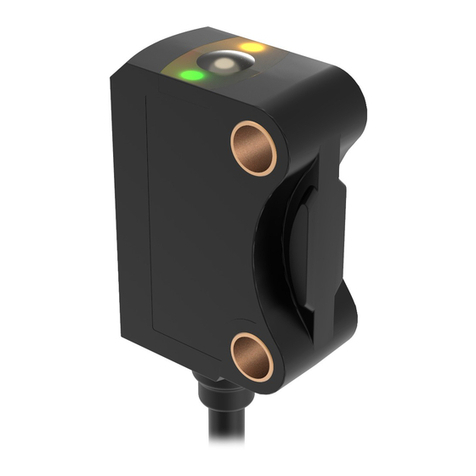
Banner LTF Series User manual

Instruction Manual
LTF Time of Flight Laser Distance Sensor
January 18, 2023
© Banner Engineering Corp. All rights reserved.

i
Contents
Chapter: 1 Product Description . . . . . . . . . . . . . . . . . . . . . . . . . . . . . . . . . . . . . . . . . 1
Models . . . . . . . . . . . . . . . . . . . . . . . . . . . . . . . . . . . . . . . . . . . . . . . . . 1
Overview . . . . . . . . . . . . . . . . . . . . . . . . . . . . . . . . . . . . . . . . . . . . . . . . 1
Features and Indicators . . . . . . . . . . . . . . . . . . . . . . . . . . . . . . . . . . . . . . 2
Display . . . . . . . . . . . . . . . . . . . . . . . . . . . . . . . . . . . . . . . . . . . . . . 2
Buttons and Icons . . . . . . . . . . . . . . . . . . . . . . . . . . . . . . . . . . . . . . . . . 2
Laser Description and Safety Information . . . . . . . . . . . . . . . . . . . . . . . . . . . . . . . 3
Class 2 Laser Models . . . . . . . . . . . . . . . . . . . . . . . . . . . . . . . . . . . . . . . 3
Chapter: 2 Sensor Installation . . . . . . . . . . . . . . . . . . . . . . . . . . . . . . . . . . . . . . . . . . 4
Mount the Device . . . . . . . . . . . . . . . . . . . . . . . . . . . . . . . . . . . . . . . . . . . . 4
Wiring Diagrams . . . . . . . . . . . . . . . . . . . . . . . . . . . . . . . . . . . . . . . . . . . . 4
Connecting to RSD1 . . . . . . . . . . . . . . . . . . . . . . . . . . . . . . . . . . . . . . . . . . 4
Chapter: 3 Sensor Programming . . . . . . . . . . . . . . . . . . . . . . . . . . . . . . . . . . . . . . . . . 6
Quick Menu . . . . . . . . . . . . . . . . . . . . . . . . . . . . . . . . . . . . . . . . . . . . . . 6
LTF Sensor Menu (MENU) . . . . . . . . . . . . . . . . . . . . . . . . . . . . . . . . . . . . . . . 6
Remote Input . . . . . . . . . . . . . . . . . . . . . . . . . . . . . . . . . . . . . . . . . . . . . . 7
Locking and Unlocking the Sensor . . . . . . . . . . . . . . . . . . . . . . . . . . . . . . . . . . . 9
Analog Output Menu (A_OUT) . . . . . . . . . . . . . . . . . . . . . . . . . . . . . . . . . . . . . 9
TEACH 4 mA (0 V) and TEACH 20 mA (10 V) . . . . . . . . . . . . . . . . . . . . . . . . . 10
Midpoint TEACH . . . . . . . . . . . . . . . . . . . . . . . . . . . . . . . . . . . . . . . . 11
Window Size . . . . . . . . . . . . . . . . . . . . . . . . . . . . . . . . . . . . . . . . . . . . . . . . . . . . . . . . . . . 12
TEACH 12 mA (5 V) . . . . . . . . . . . . . . . . . . . . . . . . . . . . . . . . . . . . . . . . . . . . . . . . . . . . . 12
Window TEACH Offset . . . . . . . . . . . . . . . . . . . . . . . . . . . . . . . . . . . . . . . . . . . . . . . . . . . 13
Adjust 4 mA (0 V) . . . . . . . . . . . . . . . . . . . . . . . . . . . . . . . . . . . . . . . . 13
Adjust 20 mA (10 V) . . . . . . . . . . . . . . . . . . . . . . . . . . . . . . . . . . . . . . 13
Slope . . . . . . . . . . . . . . . . . . . . . . . . . . . . . . . . . . . . . . . . . . . . . . 13
Loss of Signal . . . . . . . . . . . . . . . . . . . . . . . . . . . . . . . . . . . . . . . . . . 14
Discrete Output Menu (D_OUT) . . . . . . . . . . . . . . . . . . . . . . . . . . . . . . . . . . . 15
Two-Point TEACH . . . . . . . . . . . . . . . . . . . . . . . . . . . . . . . . . . . . . . . 16
Midpoint TEACH . . . . . . . . . . . . . . . . . . . . . . . . . . . . . . . . . . . . . . . . 18
Window Size . . . . . . . . . . . . . . . . . . . . . . . . . . . . . . . . . . . . . . . . . . . . . . . . . . . . . . . . . . . 18
TEACH Midpoint . . . . . . . . . . . . . . . . . . . . . . . . . . . . . . . . . . . . . . . . . . . . . . . . . . . . . . . . 18
Window TEACH Offset . . . . . . . . . . . . . . . . . . . . . . . . . . . . . . . . . . . . . . . . . . . . . . . . . . . 19
Adjust Switch Point One . . . . . . . . . . . . . . . . . . . . . . . . . . . . . . . . . . . . 19
Adjust Switch Point Two . . . . . . . . . . . . . . . . . . . . . . . . . . . . . . . . . . . . 20
TEACH Switch Point . . . . . . . . . . . . . . . . . . . . . . . . . . . . . . . . . . . . . . 20
Adjust Switch Point . . . . . . . . . . . . . . . . . . . . . . . . . . . . . . . . . . . . . . . 21
Mode . . . . . . . . . . . . . . . . . . . . . . . . . . . . . . . . . . . . . . . . . . . . . . 21
Switch Point Reference (SPtRef) . . . . . . . . . . . . . . . . . . . . . . . . . . . . . . . . 22
Switch Point TEACH Offset . . . . . . . . . . . . . . . . . . . . . . . . . . . . . . . . . . . 22
Switch Point Hysteresis . . . . . . . . . . . . . . . . . . . . . . . . . . . . . . . . . . . . . 22
Timer . . . . . . . . . . . . . . . . . . . . . . . . . . . . . . . . . . . . . . . . . . . . . . 24
Polarity . . . . . . . . . . . . . . . . . . . . . . . . . . . . . . . . . . . . . . . . . . . . . 24
Input Menu (INPUT) . . . . . . . . . . . . . . . . . . . . . . . . . . . . . . . . . . . . . . . . . 24
Input Type . . . . . . . . . . . . . . . . . . . . . . . . . . . . . . . . . . . . . . . . . . . . 25
Input Active . . . . . . . . . . . . . . . . . . . . . . . . . . . . . . . . . . . . . . . . . . . 25
Measure Menu (MEASURE) . . . . . . . . . . . . . . . . . . . . . . . . . . . . . . . . . . . . . 25
Speed . . . . . . . . . . . . . . . . . . . . . . . . . . . . . . . . . . . . . . . . . . . . . . 26
Trigger . . . . . . . . . . . . . . . . . . . . . . . . . . . . . . . . . . . . . . . . . . . . . 26
Display Menu (DISPLAY) . . . . . . . . . . . . . . . . . . . . . . . . . . . . . . . . . . . . . . 28
Units . . . . . . . . . . . . . . . . . . . . . . . . . . . . . . . . . . . . . . . . . . . . . . 29
Zero and Shift . . . . . . . . . . . . . . . . . . . . . . . . . . . . . . . . . . . . . . . . . . 29
View . . . . . . . . . . . . . . . . . . . . . . . . . . . . . . . . . . . . . . . . . . . . . . . 30

ii
Sleep . . . . . . . . . . . . . . . . . . . . . . . . . . . . . . . . . . . . . . . . . . . . . . 31
Information Menu (INFO) . . . . . . . . . . . . . . . . . . . . . . . . . . . . . . . . . . . . . . . 31
Reset Menu (RESET) . . . . . . . . . . . . . . . . . . . . . . . . . . . . . . . . . . . . . . . . 31
Factory Default Settings . . . . . . . . . . . . . . . . . . . . . . . . . . . . . . . . . . . . . . . 32
Chapter: 4 Sync Master/Slave . . . . . . . . . . . . . . . . . . . . . . . . . . . . . . . . . . . . . . . . . 33
Chapter: 5 Additional Remote TEACH Procedures . . . . . . . . . . . . . . . . . . . . . . . . . . . . . . 34
TEACH Analog Output and Discrete Output Switch Points Together . . . . . . . . . . . . . . . 34
TEACH Analog Output and Discrete Output Midpoints Together . . . . . . . . . . . . . . . . . . 34
Chapter: 6 Specifications for the LTF Sensor . . . . . . . . . . . . . . . . . . . . . . . . . . . . . . . . . 36
Repeatability Performance . . . . . . . . . . . . . . . . . . . . . . . . . . . . . . . . . . . . . . 37
Dimensions . . . . . . . . . . . . . . . . . . . . . . . . . . . . . . . . . . . . . . . . . . . . . . 38
Chapter: 7 Troubleshooting . . . . . . . . . . . . . . . . . . . . . . . . . . . . . . . . . . . . . . . . . . 39
Chapter: 8 Sensor Menu Full Map . . . . . . . . . . . . . . . . . . . . . . . . . . . . . . . . . . . . . . . 40
Chapter: 9 Accessories . . . . . . . . . . . . . . . . . . . . . . . . . . . . . . . . . . . . . . . . . . . . . 41
Cordsets . . . . . . . . . . . . . . . . . . . . . . . . . . . . . . . . . . . . . . . . . . . . . . . 41
Brackets . . . . . . . . . . . . . . . . . . . . . . . . . . . . . . . . . . . . . . . . . . . . . . . 41
RSD1 Remote Display . . . . . . . . . . . . . . . . . . . . . . . . . . . . . . . . . . . . . . . . 42
Chapter: 10 Banner Engineering Corp Limited Warranty . . . . . . . . . . . . . . . . . . . . . . . . . . . 43
. . . . . . . . . . . . . . . . . . . . . . . . . . . . . . . . . . . . . . . . . . . . . . . . . . . . 43

1 © Banner Engineering Corp. www.bannerengineering.com
PRODUCT DESCRIPTION
1. Product Description
Laser distance sensor with both analog and discrete (switched) outputs
WARNING
!
DO NOT USE THIS DEVICE FOR PERSONNEL PROTECTION
Using this device for personnel protection could result in serious injury or death.
• This device does not include the self-checking redundant circuitry necessary to allow its use in personnel
safety applications. A device failure or malfunction can cause either an energized (on) or de-energized (off)
output condition.
1.1. Models
NOTE: Some model combinations may not be available.
1.2. Overview
The LTF Time of Flight Laser Distance Sensor is designed for precise, long-distance measurements. A 2-line LCD shows the real-time distance
measurement, in either millimeters or inches,and the analog output measurement, in milliamps or volts, when the sensor is in Run mode.
See Factory Defaults for a list of sensor default settings.
Models with current or voltage analog outputs are available. This manual provides the display information and the navigation paths for the current
models with the voltage model text in parentheses if it is different.
• High-performance time of flight measurement
• Extended ranges up to 24 m
• Reliably detects challenging targets
• Fast setup with an intuitive interface
Family Connector
Blank = 2 m Integral Cable
Q = Rotatable M12/Euro QD
QP = PVC M12/Euro Pigtail QD
W/30 = 9 m Integral Cable
QD models require mating cordset
Q
Range
12
LTF
12
24
Laser
Class
C2
C2 = Class 2I = 4 to 20 mA analog
and (1) NPN/PNP discrete
U= 0 to 10 V analog
and (1) NPN/PNP discrete
LD = Laser diffuse
ILD
Output
Sensing
Mode
= 12 m
= 24 m

© Banner Engineering Corp. www.bannerengineering.com 2
PRODUCT DESCRIPTION
1.2.1. Features and Indicators
1.2.2. Display
1.2.3. Buttons and Icons
Use the sensor buttons Down, Up, Enter, and Escape to program the sensor and to access sensor information.
Figure 1: Features
Three LED indicators provide an ongoing indication of the sensing status.
Analog Output LED Indicator
• Solid Amber = Displayed distance is within the taught analog
output window
• Off = Displayed distance is outside the taught analog output
window
Power LED Indicator
• Solid Green = Normal operation, power On and laser On
• Flashing Green (1 Hz) = Power On and laser Off (laser
enable mode)
Discrete Output LED Indicator
• Solid Amber = Discrete Output is On
• Off = Discrete Output is Off
Figure 2: shown in Run Mode
The display is a 2-line, 8-character LCD. The main screen is the Run mode screen, which
shows the real-time distance measurement and the analog output measurement.
Down and Up Buttons
Press Down and Up to:
• Access the Quick Menu from Run mode
• Navigate the menu systems
• Change programming settings
• Change individual digit values in distance based settings
When navigating the menu systems, the menu items loop.
Enter Button
Press Enter to:
• Access the Sensor Menu from Run mode
• Access the submenus
• Move right one digit in distance based settings
• Save changes
In the Sensor Menu, a checkmark in the lower right corner of the display indicates that pressing Enter accesses a submenu.
Press Enter to save changes. New values flash rapidly and the sensor returns to the parent menu.
Analog Output
LED Indicator
Power
LED Indicator
Discrete Output
LED Indicator
Up and Down
Buttons
Enter Button
Escape Button
Display

3 © Banner Engineering Corp. www.bannerengineering.com
PRODUCT DESCRIPTION
1.3. Laser Description and Safety Information
CAUTION
!
RETURN DEFECTIVE UNITS TO THE MANUFACTURER.
Use of controls or adjustments or performance of procedures other than those specified herein may result in haz-
ardous radiation exposure.
• Do not attempt to disassemble this sensor for repair. A defective unit must be returned to the manufacturer.
1.3.1. Class 2 Laser Models
CAUTION
!
NEVER STARE DIRECTLY INTO THE SENSOR LENS.
Laser light can damage your eyes.
• Avoid placing any mirror-like object in the beam. Never use a mirror as a retroreflective target.
Escape Button
Press Escape to:
• Leave the current menu and return to the parent menu
• Return to Run mode from the Quick Menu
IMPORTANT: Pressing Escape discards any unsaved programming changes.
In the Sensor Menu, a return arrow in the upper left corner of the display indicates that pressing Escape returns to the parent menu.
Press and hold Escape for 2 seconds to return to Run mode from any menu or remote teach.
A lock symbol displays in the upper left corner of the display to indicate when the sensor is locked.
For Safe Laser Use - Class 2 Lasers
• Do not stare at the laser.
• Do not point the laser at a person’s eye.
• Mount open laser beam paths either above or below eye level, where practical.
• Terminate the beam emitted by the laser product at the end of its useful path.
Reference IEC 60825-1:2007, Section 8.2.
Class 2 Lasers
Class 2 lasers are lasers that emit visible radiation in the wavelength range from 400 nm to 700 nm, where eye
protection is normally afforded by aversion responses, including the blink reflex. This reaction may be expected to
provide adequate protection under reasonably foreseeable conditions of operation, including the use of optical
instruments for intrabeam viewing.
Figure 3: FDA (CDRH) warning label
(Class 2)
Class 2 Laser Safety Notes
Low-power lasers are, by definition, incapable of causing eye injury within the duration of a blink (aversion
response) of 0.25 seconds. They also must emit only visible wavelengths (400 to 700 nm). Therefore, an ocular
hazard may exist only if individuals overcome their natural aversion to bright light and stare directly into the laser
beam.

© Banner Engineering Corp. www.bannerengineering.com 4
SENSOR INSTALLATION
2. Sensor Installation
NOTE: Handle the sensor with care during installation and operation. Sensor windows soiled by fingerprints, dust, water, oil, etc. may create stray
light that may degrade the peak performance of the sensor. Blow the window clear using filtered, compressed air, then clean as necessary using
70% isopropyl alcohol and cotton swabs or water and a soft cloth.
2.1. Mount the Device
1. If a bracket is needed, mount the device onto the bracket.
2. Mount the device (or the device and the bracket) to the machine or equipment at the desired location. Do not tighten the mounting
screws at this time.
3. Check the device alignment.
4. Tighten the mounting screws to secure the device (or the device and the bracket) in the aligned position.
2.2. Wiring Diagrams
2.3. Connecting to RSD1
The following diagram depicts the connection of the LTF to the optional RSD1 accessory.
Figure 3: LTF to RSD1
Use these cordsets to connect the RSD1 to the LTF sensor or to other devices, such as PLC inputs, IO-Link masters, or control systems.
Figure 1: Analog Current Model Figure 2: Analog Voltage Model
Key
• 1 = Brown
• 2 = White
• 3 = Blue
• 4 = Black
• 5 = Gray
shield
+
12-30V dc
D_Out
A_Out
Input
–
Load
* User-configurable PNP/NPN setting
4-20 mA
3
1
2
4
5
NPN
or
PNP
shield
+
12-30V dc
D_Out
A_Out
Input
–
Load
* User-configurable PNP/NPN setting
3
1
2
4
5
NPN
or
PNP
0-10V
2
3
4
1
5
MQDEC3-503SS
Double Ended Shielded
MQDEC3-506SS
MQDEC3-515SS
MQDEC3-530SS
MQDEC2-506
Flying Lead Shielded
MQDEC2-515
MQDEC2-530
RSD1
LTF
MQDEC3-503SS
Double Ended Shielded
MQDEC3-506SS
MQDEC3-515SS
MQDEC3-530SS

5 © Banner Engineering Corp. www.bannerengineering.com
SENSOR INSTALLATION
5-Pin Male Threaded and 5-Pin Female Quick Disconnect M12 Cordset with Shield—Double Ended
Model Length "L1" Style Pinout (Male) Pinout (Female)
MQDEC3-503SS 0.91 m (2.99 ft)
Female Straight/Male Straight
MQDEC3-506SS 1.83 m (6 ft)
MQDEC3-515SS 4.58 m (15 ft)
MQDEC3-530SS 9.2 m (30.2 ft)
• 1 = Brown
• 2 = White
• 3 = Blue
• 4 = Black
• 5 = Gray
5-Pin Threaded M12 Cordsets with Shield—Single Ended
Model Length Style Dimensions Pinout (Female)
MQDEC2-506 2 m (6.56 ft)
Straight
• 1 = Brown
• 2 = White
• 3 = Blue
• 4 = Black
• 5 = Gray
MQDEC2-515 5 m (16.4 ft)
MQDEC2-530 9 m (29.5 ft)
MQDEC2-550 15 m (49.2 ft)
MQDEC2-575 23 m (75.44 ft)
MQDEC2-5100 30.5 m (100 ft)
MQDEC2-506RA 2 m (6.56 ft)
Right-Angle
MQDEC2-515RA 5 m (16.4 ft)
MQDEC2-530RA 9 m (29.5 ft)
MQDEC2-550RA 15 m (49.2 ft)
MQDEC2-575RA 23 m (75.44 ft)
MQDEC2-5100RA 31 m (101.68 ft)
1
4
5
3
2
2
3
4
1
5
M12 x 1
14.5
ø 5.9
14.5
“L1”
47.4 47.4
M12 x 1
44 Typ.
ø 14.5
M12 x 1
2
3
4
1
5
32 Typ.
[1.26"]
30 Typ.
[1.18"]
ø 14.5 [0.57"]
M12 x 1

© Banner Engineering Corp. www.bannerengineering.com 6
SENSOR PROGRAMMING
3. Sensor Programming
Program the sensor using the buttons on the sensor or the remote input (limited programming options).
From Run mode, use the buttons to access the Quick Menu and the Sensor Menu. See Quick Menu for the LTF and Sensor Menu (MENU) for
more information on the options available from each menu. For TEACH options, follow the TEACH instructions.
In addition to programming the sensor, use the remote input to disable the buttons for security, preventing unauthorized or accidental program-
ming changes. See Remote Input for more information.
3.1. Quick Menu
The sensor includes a Quick Menu with easy access to view and change the analog and discrete output switch points. Access the Quick Menu
by pressing Down or Up from Run mode. When in the Quick Menu, the current distance measurement displays on the first line and the menu
name and the analog value alternate on the second line of the display. Press Enter to access the switch points. Press Down and Up to change
each digit. Press Enter to move right one digit. After reviewing each digit, press Enter again to save the new value and return to the Quick Menu.
Press Cancel to ignore any changes made if only some digits have been changed.
Figure 2: Quick Menu Map (Window Mode)
3.2. LTF Sensor Menu (MENU)
Access the Sensor Menu by pressing Enter from Run mode. The Sensor Menu is also accessible from the Quick Menu: navigate to MENU and
press Enter. The Sensor Menu includes several submenus that provide access to view and change sensor settings and to view sensor informa-
tion.
Figure 1: Accessing the menus
See Quick Menu for the LTF See Sensor Menu (MENU)
from Run Mode
Access
Quick Menu
Access
Sensor Menu
Quick Menu
4mA Pt (value)
MENU
20mA Pt (value)
SPt1 Pt (value)
SPt2 Pt (value)
access Sensor
Menu (Top Menu)
Run
Mode
set value with
or
Save setting
and return to
Quick Menu
Cancel and
return to
Quick Menu
* In Setpoint Mode,
SPt1 Pt is replaced by SPt
and SPt2 Pt is not available.

7 © Banner Engineering Corp. www.bannerengineering.com
SENSOR PROGRAMMING
Figure 3: Sensor Menu Basic Map
See Sensor Menu Full Map and the Menu sections of this manual for more information.
3.3. Remote Input
Use the remote input to program the sensor remotely. The remove input is disabled by default. Activate remote input using the buttons to navigate
to the Input Type menu option.
The remote input provides limited programming options and is Active Low by default. For Active Low, connect the gray input wire to ground (0 V
DC), with a remote switch connected between the wire and ground. To use the Active High function, configure the sensor for Active High using
the buttons on the sensor, then connect the gray input wire to V+ (12 to 30 V DC). Pulse the remote input according to the diagram and the
instructions provided in this manual.
The length of the individual programming pulses is equal to the value T: 0.04 seconds ≤ T ≤ 0.8 seconds.
Exit remote programming modes by holding the remote input low for > 2 seconds, or waiting for the automatic 60-second timeout, or by pressing
and holding Escape for 2 seconds. The sensor returns to Run mode without saving any new settings.
MENU A_OUT
Access analog output settings
MENU D_OUT
Access discrete output settings
MENU INPUT
Select input line settings (remote TEACH, trigger mode, etc.)
MENU MEASURE
Select response speed and trigger measurement
MENU DISPLAY
Select display units, zero reference, shift, and orientation
MENU INFO
View sensor information
MENU RESET
Reset to factory defaults
Sensor Menu
Run
Mode
(See Sensor Menu Full Map for the complete map)
or
or
Go Back to Parent Menu
Select Menu Item
Press to Save Setting
Press and Hold to Go Back
to Run Mode

© Banner Engineering Corp. www.bannerengineering.com 8
SENSOR PROGRAMMING
Figure 4: Remote Input Map
5x
6x
4x
3x
2x
1x Set Window Size to X1 , then back to Run mode
Set Window Size to X2 , then back to Run mode
Set Window Size to X3 , then back to Run mode
Set Window Size to X4 , then back to Run mode
Set Window Size to X5 , then back to Run mode
Set Window Size to X6 , then back to Run mode
1x
2x
1x
1x
2x
1x Select Slope Positive, then back to Run mode
Select Slope Negative, then back to Run mode
8x
Enter Remote TEACH RMT TCH with measurement value
Enter Remote Setup REMOTE SETUP
Teaching..(4mA) Tch4mA with measurement value, then to Tch20mA
Teaching..(20mA) Tch20mA with measurement value, then back to Run mode
1x
REMOTE TEACHREMOTE SETUP
Slope Slope value (positive or negative)
Window Size WndSize with value
Sensor Lock / Unlock Locks or Unlocks Sensor
Lock Sensor
Unlock Sensor
Reset to Default Settings Resets Sensor to Factory Default Settings
0.04 seconds < T < 0.8 seconds
Timing between Pulse groups > 1 second
Pulse Timing (T)
NOTE: Follow procedure for the TEACH/SET method
(highlighted in black box) chosen in the TEACH Selection menu.
Timeout is 60 seconds.
3x
2x Teaching.. (SPt1) TchSPt1 with measurement value, then to TchSPt2
Teaching..(SPt2) TchSPt2 with measurement value, then back to Run mode
1x
3x Teaching.. (TchA&D1) Tch4mA and TchSPt1 with measurement value, then to TchA&D2
Teaching..(TchA&D2) Tch20mA and TchSPt2 with measurement value, then
1x
4x Teaching.. (Tch12mA) Tch12mA with measurement value, then back to Run mode
5x Teaching.. (TchMdPt) TchMdPt (teaches SPt in Switch Mode) with measurement value, then
6x Teaching.. (TchA&D) Tch12mA and TchMdPt (teaches SPt in Switch Mode) with measurement
value, then back to Run mode
5x
6x
4x
3x
2x
1x Set Mode to Alarm, then back to Run mode
Set Mode to Health, then back to Run mode
Set Mode to Switch , then back to Run mode
Set Mode to Window , then back to Run mode
Sensor Mode Mode with current value
2x
Run
Mode
2x
1x
4x
back to Run mode
back to Run mode
Refer to the Window size table for the acceptable values.

9 © Banner Engineering Corp. www.bannerengineering.com
SENSOR PROGRAMMING
3.4. Locking and Unlocking the Sensor
Use the lock and unlock feature to prevent unauthorized or accidental programming changes. A lock symbol displays in the upper left corner of
the display to indicate when the sensor is locked. When locked, the menus are available to view settings, but the values cannot be changed. The
remote input is also disabled, except for the unlock function.
Button Instructions--To lock or unlock the sensor using the buttons, press and hold Down and Escape simultaneously for 3 seconds.
Remote Input Instructions
1) Access the setup mode.
2) Access the lock/unlock function.
3) Lock or unlock the sensor.
3.5. Analog Output Menu (A_OUT)
Use the Analog Output menu to view or change:
• 4 mA (0 V) setpoint
• 20 mA (10 V) setpoint
• 12 mA (5 V) window
• Slope
• Loss of signal behavior
Table 1:Remote TEACH window sizes
Variable
Remote TEACH Window Size (mm)
LTF12 LTF24
X1 10 10
X2 20 20
X3 100 100
X4 500 500
X5 2000 2000
X6 11950 23950
Action Result
Double-pulse the remote input.
"REMOTE SETUP" displays.
Action Result
Four-pulse the remote input. "LOCK" and the current status (unlocked or locked)
display.
Action Result
Unlock : Single-pulse the remote line. "Unlocked" flashes and the sensor returns to Run
mode. The sensor is unlocked.
Lock: Double-pulse the remote input.
"Locked" flashes and the sensor returns to Run
mode. The sensor is locked and the lock symbol
displays in the upper left corner.
TT
T
TT
TTT
TT
T
TT
T

© Banner Engineering Corp. www.bannerengineering.com 10
SENSOR PROGRAMMING
Figure 5: Analog Output Menu Map
3.5.1. TEACH 4 mA (0 V) and TEACH 20 mA (10 V)
The Tch4mA (Tch0V) and Tch20mA (Tch10V) options use targets to set the 4 mA (0 V) and 20 mA (10 V) to the desired setpoints. When using
the buttons, only one value needs to be set if the second value is valid. When using the remote input, both values must be set.
Navigate:MENU > A_OUT > Tch2Pt > Tch4mA (Tch0V) or navigate: MENU > A_OUT > Tch2Pt > Tch20mA (Tch10V)
Remote input:Available
Button Instructions
1) Present the target.
2) Access the TEACH mode and TEACH the sensor.
3) Repeat steps 1 to 2 for the other setpoint, if desired.
Remote Input Instructions
Action Result
Present the target. The target must be within the sensor's measurement range. The target's analog output measurement and distance
measurement values display.
Action Result
Navigate: MENU > A_OUT > Tch2Pt > Tch4mA (Tch0V)
OR
Navigate: MENU > A_OUT > Tch2Pt > Tch20mA (Tch10V)
The selected TEACH mode and "Teaching" display
while the sensor is being taught.
TEACH Accepted
The new value is shown on the second line of the
display and flashes before it is saved and the sensor
returns to the parent menu.
TEACH Not Accepted
"FAIL" and a warning message display, and the
sensor returns to the parent menu.
MENU A_OUT
or
or
Go Back to Parent Menu
Select Menu Item
Press to Save Setting
Press and Hold to Go Back
to Run Mode
Adj20mA +12000mm
Adj4mA +00050mm
Tch4mA 50mm
Tch20mA 12000mm
Tch2Pt Tch20mA
Tch2Pt Tch4mA
WndSize +02000mm
Tch12mA 6000mm
TchMid Tch12mA
TchMid WndSize
Slope Negative
Slope Positive
LossSig 20.5 mA
LossSig Hold
LossSig 3.5 mA
A_OUT Adj4mA
A_OUT Adj20mA
A_OUT Tch2Pt
A_OUT TchMid
A_OUT Slope
A_OUT LossSig
Offset 0mm
TchMid Offset

11 © Banner Engineering Corp. www.bannerengineering.com
SENSOR PROGRAMMING
Teaches both the 4 mA (0 V) and 20 mA (10 V) setpoints.
1) Access the TEACH mode.
2) Present the target.
3) TEACH the sensor.
4) Present the target.
5) TEACH the sensor.
3.5.2. Midpoint TEACH
Action Result
Single-pulse the remote input.
"RMT TCH" and the current measurement value
display.
Action Result
Present the 4 mA (0 V) target. "RMT TCH" and the target's measurement value
display.
Action Result
Single-pulse the remote input.
"Tch4mA (Tch0V) Teaching" displays while the
sensor is being taught.
TEACH Accepted
The new value displays on the second line of the
display, flashes, and then "Tch20mA (Tch10V)" and
the current measurement value display.
TEACH Not Accepted
"FAIL" flashes, the sensor returns to step 2, and
"RMT TCH" displays.
Action Result
Present the 20 mA (10 V) target. "Tch20mA (Tch10V)" and the target's measurement
value display.
Action Result
Single-pulse the remote input.
"Tch20mA (Tch10V) Teaching" displays while the
sensor is being taught.
TEACH Accepted
The new value displays on the second line of the
display, flashes, and the sensor returns to Run mode.
TEACH Not Accepted
"FAIL" flashes, the sensor returns to step 2, and
"RMT TCH" displays.
Figure 6: Window and Midpoint Example
The Midpoint TEACH uses both the window size and the 12 mA (5 V) setpoint to
determine the actual measurement window. For example, a window of 200 mm with a
12 mA (5 V) setpoint of 600 mm places the measurement window from 500 mm to 700
mm.
To use the Midpoint TEACH:
1) Set the window size.
2) Set the measurement window using TEACH 12 mA (5 V) on page
12.
The Analog Output Midpoint TEACH and the Discrete Output Midpoint TEACH are
independent settings (see Midpoint TEACH on page 18).
T
T
T
4 mA
20 mA
12 mA
(500 mm) (700 mm)
(600 mm)
Midpoint

© Banner Engineering Corp. www.bannerengineering.com 12
SENSOR PROGRAMMING
3.5.2.1. Window Size
The A_OUT > TchMid > WndSize option sets the window size that the Midpoint TEACH uses to set the 4 mA (0 V) and 20 mA (10 V) setpoints.
The taught surface must be inside the defined sensing range, and at least one setpoint (with offset applied, if any) must be located within the
sensing range.
The Analog Output window size is a different setting than the Discrete Output window size when defined using the push buttons.
Navigate: MENU > A_OUT > TchMid > WndSize
Remote Input: Available
1) Access the Window Size mode.
2) Set the window size.
3.5.2.2. TEACH 12 mA (5 V)
The Tch12mA (Tch5V) option sets the midpoint that determines the actual measurement window.
Navigate: MENU > A_OUT > TchMid > Tch12mA (Tch5V)
Remote Input: Available
Button Instructions
1) Present the target.
2) Access the TEACH 12 mA (5 V) mode and TEACH the sensor.
Parameters LTF12 LTF24
Window Size Minimum 10 mm 10 mm
Window Size Maximum 11950 mm 23950 mm
Range 50 mm to 12000 mm 50 mm to 24000 mm
Default Window Size 2000 mm 2000 mm
Method Action Result
Push Button Navigate: MENU > A_OUT > TchMid > WndSize "WndSize" and the current window size value
display.
Remote Input
a. Double-pulse the remote input to enter setup mode.
b. Three-pulse the remote input to enter window size
mode.
a. "REMOTE SETUP" displays.
b. "WndSize" and the current window size
value display.
Method Action Result
Push Button
a. Use the Up and Down buttons to set the desired window size—the value changes in
increments of 2.
b. Press Enter to save the new value.
a. "WndSize" and the new value
display.
b. The new value flashes and the sensor
returns to "TchMid WndSize".
Remote Input
(Sets A_OUT and
D_OUT window
Size)
Pulse the remote input 1 to 6 times to select the desired window size.
1 pulse: 10 mm
2 pulses: 20 mm
3 pulses: 100 mm
4 pulses: 500 mm
5 pulses: 2000 mm
6 pulses: 11950 mm for the LTF12; 23950 mm for the LTF24
The new value flashes and the sensor
returns to Run mode.
Action Result
Present the target. The target's analog output measurement and distance
measurement values display.
TT
T
TT
T
T
T

13 © Banner Engineering Corp. www.bannerengineering.com
SENSOR PROGRAMMING
Remote Input Instructions
1) Access the TEACH mode.
2) Present the target.
3) TEACH the sensor.
3.5.2.3. Window TEACH Offset
Use the A_OUT > TchMid > Offset menu to set an offset from the taught distance used during a 12 mA (5 V) TEACH. By default, the value is
0 mm because the window is centered around the taught distance. A positive offset value always shifts the window towards the sensor.
3.5.3. Adjust 4 mA (0 V)
The Adj4mA (Adj0V) option manually adjusts the distance at which the Analog Output is 4mA (0 V). The value is adjustable within the sensor's
range. It is required to at least maintain the minimum window size.
Navigate: MENU > A_OUT > Adj4mA (Adj0V)
Remote Input: Not available
Default: 50 mm
3.5.4. Adjust 20 mA (10 V)
The Adj20mA (Adj10V) option manually adjusts the distance at which the Analog Output is 20 mA (10 V). The value is adjustable between the
sensor's range. It is required to at least maintain the minimum window size.
Navigate: MENU > A_OUT > Adj20mA (Adj10V)
Remote Input:Not available
Default: 12000 mm for LTF12, 24000 mm for LTF24
3.5.5. Slope
The Slope option sets the slope as positive or negative. This swaps the 4 mA and 20 mA (0 V and 10 V) values.
Navigate: MENU > A_OUT > Slope
Action Result
Navigate: MENU > A_OUT > TchMid > Tch12mA (Tch5V).
"Tch12mA (Tch5V) Teaching" displays while the sensor is being taught.
TEACH Accepted
The new value is shown on the second line of the display and flashes before
it is saved and the sensor returns to "TchMid Tch12mA (Tch5V)".
TEACH Not Accepted
"FAIL" and a warning message display and the sensor returns to "Tch Mid
Tch12mA (Tch5V)".
Action Result
Single-pulse the remote input.
"RMT TCH" and the current measurement value display.
Action Result
Present the target. "RMT TCH" and the target's measurement value display.
Action Result
Four-pulse the remote input.
"Tch12mA (Tch5V) Teaching" displays while the sensor is being taught.
TEACH Accepted
The new value displays on the second line of the display, flashes, and the
sensor returns to Run mode
TEACH Not Accepted
"FAIL" flashes, the sensor returns step 2, and "RMT TCH" displays.
T
TT
TTT
TT

© Banner Engineering Corp. www.bannerengineering.com 14
SENSOR PROGRAMMING
Remote Input: Available
Default: Positive
1) Access the slope setting.
2) Set the slope.
3.5.6. Loss of Signal
The LossSig option sets the Analog Output value used by the sensor during a loss of signal. When a signal is restored, measurement resumes.
Navigate: Menu > A_Out > LossSig
Remote Input: Not available
Default: 3.5 mA (0 V)
Figure 7: Slope—Current-Sourcing Models
The analog current output tracks slightly beyond each window limit (from 3.8 mA
to 20.2 mA)
Figure 8: Slope—Voltage-Sourcing Models
The analog voltage output tracks slightly beyond the upper window limit (up to
10.2 V)
Method Action Result
Push Button Navigate: MENU > A_OUT > Slope "Slope" and the current setting display.
Remote Input
a. Double-pulse the remote input to enter setup mode.
b. Single-pulse the remote input to access A_OUT
Slope.
a. "REMOTE SETUP" displays.
b. "Slope" and the current setting display.
Method Action Result
Push Button
a. Use Down and Up to change the slope between Positive and Negative.
b. Press Enter to save the selection.
a. The selection flashes rapidly on the
display.
b. The selection is saved and the sensor
returns to "A_OUT Slope".
Remote Input Positive slope: Single-pulse the remote input
Negative slope: Double-pulse the remote input
The selection flashes rapidly on the display,
and the sensor returns to Run mode.
4
Near
Window
Far
Window
20
Target Position
Analog Output (mA)
Positive
Slope
0
Near
Window
Far
Window
10
Analog Output (V dc)
Positive
Slope
Target Position
TT
T
T
T
TT
T

15 © Banner Engineering Corp. www.bannerengineering.com
SENSOR PROGRAMMING
The Range advanced measurement behavior is affected by the Loss of Signal option. For additional information on advanced measurements,
see Trigger on page 26. The Range advanced measurement tracks a maximum and a minimum during the measurement period, and calculates
the range as follows:
Range = maximum distance – minimum distance
If the maximum and/or minimum measurements are outside of the taught setpoints, the Loss of Signal option determines how the range is calcu-
lated.
3.6. Discrete Output Menu (D_OUT)
Use this menu to view or change
• Setpoints
• Midpoint
• Mode
• Timers
• Polarity
Option Description
3.5 mA (0 V)
The Analog Output switches to this value 2 seconds after a loss of signal. When advanced measurements are enabled, the
Analog Output is updated to this value immediately upon the release of the trigger input. For Voltage models, this is 0 V.
(Default)
20.5 mA (10.5 V) The Analog Output switches to this value 2 seconds after a loss of signal. When advanced measurements are enabled, the
Analog Output is updated to this value immediately upon the release of the trigger input. For Voltage models, this is 10.5 V.
Hold The Analog Output holds the last value indefinitely during a loss of signal. When advanced measurements are enabled, the
last value is held across the triggered measurement periods.
Option Sensor Behavior in Range Mode
3.5 mA (0 V) If the maximum or minimum measurement is outside of the taught setpoints, the sensor outputs 3.5 mA (0 V) to indicate an
out of range measurement.
20.5 mA (10.5 V) If the maximum or minimum measurement is outside of the taught setpoints, the sensor outputs 20.5 mA (10.5 V) to indicate
an out of range measurement.
Hold The sensor limits the maximum and minimum measurements so that they cannot exceed the taught setpoints.

© Banner Engineering Corp. www.bannerengineering.com 16
SENSOR PROGRAMMING
Figure 9: Discrete Output Menu Map
3.6.1. Two-Point TEACH
The TchSpt1 and TchSPt2 options teach the desired switch points. When using the buttons, the switch points can be taught independently. Both
values must be taught when using the remote input.
NOTE: When in Switch mode, see TEACH Switch Point.
Navigate:MENU > D_OUT > Tch2Pt > TchSPt1 and navigate: MENU > D_OUT > Tch2Pt > TchSPt2
Remote Input: Available
Button Instructions
1) Present the target.
2) Access the TEACH mode and TEACH the sensor.
Action Result
Present the target. The target must be within the sensor's range.. The target's analog output measurement and distance
measurement value display.
MENU D_OUT
or
or
Go Back to Parent Menu
Select Menu Item
Press to Save Setting
Press and Hold to Go Back
to Run Mode
OffDly 0 ms
Off1Sho 0 ms
OnDly 0 ms
On1Sho 0 ms
AdjSPt2 +12000mm
AdjSPt1 +00050mm
D_OUT AdjSPt1
D_OUT AdjSPt2
D_OUT Tch2Pt
D_OUT TchMid
D_OUT Mode
D_OUT Polarity
TchSPt1 50mm
TchSPt2 12000mm
Tch2Pt TchSPt2
Tch2Pt TchSPt1
WndSize +00020mm
TchMdPt 6000mm
TchMid TchMdPt
TchMid WndSize
D_OUT Timer
Timer On1Sho
Timer OffDly
Polarity NPN
Polarity PNP
Mode Wnd
Mode Wnd
Timer Off1Sho
Timer OnDly
Mode Health
Mode Alarm
Mode Swtch
Mode Swtch
D_OUT SPtRef
(in SPt mode only)
SPtRef Object
SPtRef Backgrnd
Offset 0mm
TchMid Offset
D_OUT Offset Offset 0 mm
(in SPtRef Custom mode only)
SPtRef Custom
The Tch2Pt, TchMid, AdjSPt1, and AdjSPt2
menus are only available in Wnd mode.
When in SPt, Alarm, or Health modes, these menus
are replaced by TchSPt and AdjSPt.
D_OUT Hyst Hyst Auto

17 © Banner Engineering Corp. www.bannerengineering.com
SENSOR PROGRAMMING
3) Repeat steps 1 to 2 for the other switch point, if desired.
Remote Input Instructions
1) Access the TEACH mode.
2) Present the target.
3) TEACH the sensor.
4) Present the target.
5) TEACH the sensor.
Action Result
Navigate: MENU > D_OUT > Tch2Pt > TchSPt1
OR
Navigate: MENU > D_OUT > Tch2Pt > TchSPt2
The selected TEACH mode and "Teaching" display
while the sensor is being taught.
TEACH Accepted
The new value is shown on the second line of the
display and flashes before it is saved and the sensor
returns to the parent menu.
TEACH Not Accepted
"FAIL" and a warning message display, and the
sensor returns to the parent menu.
Action Result
Single-pulse the remote input.
"RMT TCH" and the current switch point value
displays.
Action Result
Present the switch point one target. "RMT TCH" and the target's measurement value
display.
Action Result
Double-pulse the remote input.
"TchSPt1 Teaching" displays while the sensor is
being taught.
TEACH Accepted
The new value displays on the second line of the
display, flashes, and the sensor goes to "TchSPt2"
and the current measurement value.
TEACH Not Accepted
"FAIL" flashes, the sensor returns to step 2, and
"RMT TCH" displays.
Action Result
Present the switch point two target. "TchSPt2" and the target's measurement value
display.
Action Result
Single-pulse the remote input.
"TchSPt2 Teaching" displays while the sensor is
being taught.
TEACH Accepted
The new value displays on the second line of the
display, flashes, and the sensor returns to Run mode.
TEACH Not Accepted
"FAIL" flashes, the sensor returns to step 2, and
"RMT TCH" displays.
T
TT
T
T
Other manuals for LTF Series
1
This manual suits for next models
1
Table of contents
Other Banner Security Sensor manuals

Banner
Banner LS2e30-300Q8 User manual

Banner
Banner Q5X User manual

Banner
Banner K30 Pro User manual

Banner
Banner LTF User manual

Banner
Banner Q45 User manual

Banner
Banner EZ-SCREEN LS User manual

Banner
Banner SLLVE23-350 User manual

Banner
Banner PVS28 Series User manual

Banner
Banner SX5 User manual

Banner
Banner EZ-SCREEN SLSP14-450Q88 User manual