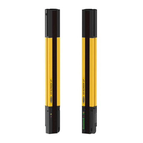
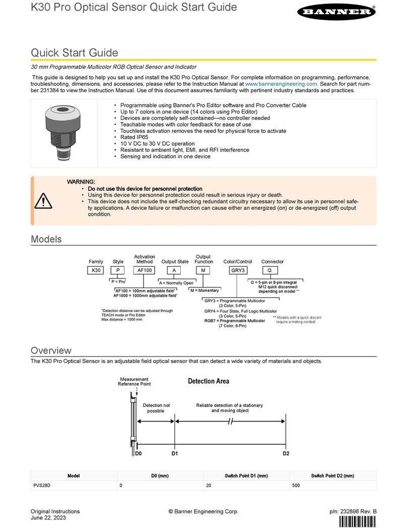
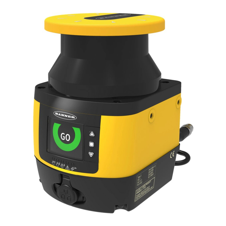
Banner EZ-SCREEN SLSP14-450Q88 User manual

EZ-SCREEN®Type2LightScreen
InstructionManual
Original Instrucons
122452 Rev. F
25 January 2017
©Banner Engineering Corp. All rights reserved
122452

Contents
1 About This Document ......................................................................................................................................................4
1.1 Important . . . Read This Before Proceeding! ......................................................................................................................................... 4
1.1.1 Use of Warnings and Cauons .................................................................................................................................................. 4
1.2 EU Declaraon of Conformity (DoC) ..................................................................................................................................................... 4
1.3 Banner Engineering Corp Limited Warranty ......................................................................................................................................... 4
1.4 Contact Us ............................................................................................................................................................................................. 5
2 Introducon .................................................................................................................................................................... 6
2.1 Features .................................................................................................................................................................................................6
2.2 System Descripon ................................................................................................................................................................................6
2.3 Appropriate Applicaons and Limitaons .............................................................................................................................................7
2.3.1 Examples: Appropriate Applicaons ........................................................................................................................................ 8
2.3.2 Examples: Inappropriate Applicaons ......................................................................................................................................8
2.4 Control Reliability and Safety Categories ...............................................................................................................................................8
2.5 Operang Features ................................................................................................................................................................................ 9
2.5.1 Trip/Latch Output .....................................................................................................................................................................9
2.5.2 Wiring Opons for Emier/Receiver Swapability .................................................................................................................... 9
2.5.3 Manual Reset/Remote Test Input and EDM ...........................................................................................................................10
2.5.4 Status Indicators .....................................................................................................................................................................10
3 Mechanical Installaon .................................................................................................................................................. 11
3.1 Mechanical Installaon Consideraons .............................................................................................................................................. 11
3.1.1 Calculang the Safety Distance (Minimum Distance) ............................................................................................................. 11
3.1.2 Reducing or Eliminang Pass-Through Hazards ..................................................................................................................... 14
3.1.3 Supplemental Safeguarding ................................................................................................................................................... 15
3.1.4 Other Consideraons .............................................................................................................................................................. 15
3.2 Mounng System Components ............................................................................................................................................................19
3.2.1 Overview of Emier/Receiver Mounng Hardware ............................................................................................................... 19
3.2.2 Mounng and Inial Alignment of Emier/Receiver Pairs ..................................................................................................... 20
4 Electrical Installaon and Tesng ................................................................................................................................... 23
4.1 Roung Cordsets .................................................................................................................................................................................. 23
4.2 Inial Electrical Connecons ............................................................................................................................................................... 23
4.2.1 Sensor Interchangeability .......................................................................................................................................................24
4.3 Inial Checkout Procedure ...................................................................................................................................................................25
4.3.1 Conguring the System for Inial Checkout ...........................................................................................................................25
4.3.2 Inial Power-Up ......................................................................................................................................................................25
4.3.3 Opcal Alignment ...................................................................................................................................................................26
4.3.4 Opcal Alignment Procedure with Mirrors ............................................................................................................................ 28
4.3.5 Trip Test ..................................................................................................................................................................................28
4.4 Electrical Connecons to the Guarded Machine .................................................................................................................................29
4.4.1 OSSD Output Connecons ......................................................................................................................................................29
4.4.2 FSD Interfacing Connecons .................................................................................................................................................. 30
4.4.3 Machine Primary Control Elements and EDM Input ............................................................................................................... 31
4.4.4 Manual Reset/Remote Test Input and EDM ...........................................................................................................................31
4.4.5 Preparing for System Operaon .............................................................................................................................................32
4.5 Reference Wiring Diagrams ..................................................................................................................................................................32
4.5.1 Generic Emier Wiring Diagram ............................................................................................................................................ 32
4.5.2 Generic Wiring to FSDs (manual reset) .................................................................................................................................. 33
4.5.3 Generic Wiring — Interface Module (2-Channel EDM, Manual Reset) ..................................................................................34
5 System Operaon ..........................................................................................................................................................35
5.1 Security Protocol ................................................................................................................................................................................. 35
5.2 Reset Procedures ................................................................................................................................................................................ 35
5.2.1 Receiver Resets ...................................................................................................................................................................... 35
5.2.2 Emier Resets ........................................................................................................................................................................ 35
5.3 Status Indicators ..................................................................................................................................................................................35
5.3.1 Receiver ..................................................................................................................................................................................36
5.3.2 Emier ....................................................................................................................................................................................36
5.4 Normal Operaon ............................................................................................................................................................................... 37
5.4.1 System Power-Up ...................................................................................................................................................................37
5.4.2 Run Mode ...............................................................................................................................................................................37
5.4.3 Manual Reset Procedure ........................................................................................................................................................37
6 Troubleshoong and Maintenance ................................................................................................................................38
6.1 Troubleshoong and Lockout Condions ........................................................................................................................................... 38
6.2 Recovery Procedures ...........................................................................................................................................................................38
6.2.1 Receiver (System Reset) .........................................................................................................................................................38
EZ-SCREEN®Type 2 Light Screen
6.2.2 Emier Reset ..........................................................................................................................................................................38
6.3 Electrical and Opcal Noise .................................................................................................................................................................39
6.3.1 Sources of Electrical Noise ..................................................................................................................................................... 39
6.3.2 Sources of Opcal Noise .........................................................................................................................................................39
6.4 Servicing and Maintenance ..................................................................................................................................................................40
6.4.1 Cleaning ..................................................................................................................................................................................40
6.4.2 Banner Engineering Corp Limited Warranty .......................................................................................................................... 40
6.4.3 Warranty Service ....................................................................................................................................................................40
6.4.4 Manufacturing Date ............................................................................................................................................................... 40
6.4.5 Disposal ................................................................................................................................................................................... 40
7 Checkout Procedures ......................................................................................................................................................41
7.1 Schedule of Checkouts ........................................................................................................................................................................ 41
7.2 Commissioning Checkout ....................................................................................................................................................................41
8 Specicaons and Accessories .......................................................................................................................................43
8.1 Specicaons .......................................................................................................................................................................................43
8.1.1 General Specicaons ............................................................................................................................................................43
8.1.2 Emier Specicaons .............................................................................................................................................................43
8.1.3 Receiver Specicaons ...........................................................................................................................................................43
8.1.4 Emier and Receiver Dimensions ........................................................................................................................................... 43
8.1.5 Bracket Dimensions .................................................................................................................................................................44
8.2 Accessories ..........................................................................................................................................................................................45
8.2.1 Cordsets ...................................................................................................................................................................................46
8.2.2 Interface Modules ................................................................................................................................................................... 48
8.2.3 Contactors ............................................................................................................................................................................... 48
8.2.4 Lens Shield ...............................................................................................................................................................................49
8.2.5 EZ-LIGHT®for EZ-SCREEN®.......................................................................................................................................................49
8.2.6 MSA Series Stands ..................................................................................................................................................................50
8.2.7 MSM Series Corner Mirrors ....................................................................................................................................................50
8.2.8 SSM Series Corner Mirrors ..................................................................................................................................................... 50
8.2.9 Accessory Mounng Brackets ................................................................................................................................................ 51
8.2.10 Alignment Aids ..................................................................................................................................................................... 52
8.2.11 Replacement Parts ............................................................................................................................................................... 52
8.2.12 Documentaon .....................................................................................................................................................................52
9 Standards and Regulaons ............................................................................................................................................. 53
9.1 Applicable U.S. Standards .................................................................................................................................................................... 53
9.2 OSHA Regulaons .................................................................................................................................................................................53
9.3 Internaonal/European Standards ...................................................................................................................................................... 53
9.4 Contact Us ........................................................................................................................................................................................... 53
10 Glossary .......................................................................................................................................................................55
EZ-SCREEN®Type 2 Light Screen
1 About This Document
1.1 Important . . . Read This Before Proceeding!
It is the responsibility of the machine designer, controls engineer, machine builder, machine operator, and/or maintenance personnel or
electrician to apply and maintain this device in full compliance with all applicable regulaons and standards. The device can provide the
required safeguarding funcon only if it is properly installed, properly operated, and properly maintained. This manual aempts to
provide complete installaon, operaon, and maintenance instrucon. Reading the manual in its enrety is highly recommended. Please
direct any quesons regarding the applicaon or use of the device to Banner Engineering.
For more informaon regarding U.S. and internaonal instuons that provide safeguarding applicaon and safeguarding device
performance standards, see Standards and Regulaons on page 53.
WARNING: User Responsibility
The user is responsible to:
• Carefully read, understand, and comply with all instrucons for this device.
• Perform a risk assessment that includes the specic machine guarding applicaon. Guidance on a compliant
methodology can be found in ISO 12100 or ANSI B11.0.
• Determine what safeguarding devices and methods are appropriate per the results of the risk assessment and
implement per all applicable local, state, and naonal codes and regulaons. See ISO 13849-1, ANSI B11.19, and/or
other appropriate standards.
• Verify that the enre safeguarding system (including input devices, control systems, and output devices) is properly
congured and installed, operaonal, and working as intended for the applicaon.
• Periodically re-verify, as needed, that the enre safeguarding system is working as intended for the applicaon.
Failure to follow any of these responsibilies may potenally create a dangerous condion that may lead to
serious injury or death.
1.1.1 Use of Warnings and Cauons
This manual contains numerous WARNING and CAUTION statements:
•Warnings refer to potenally hazardous situaons which, if not avoided, may lead to serious injury or death.
•Cauons refer to potenally hazardous situaons which, if not avoided, which may lead to minor or moderate injury or
potenal damage to equipment. Cauons are also used to alert against unsafe pracces.
These statements are intended to inform the machine designer and manufacturer, the end user, and maintenance personnel, how to
avoid misapplicaon and eecvely apply the EZ-SCREEN Type 2 Light Screen to meet the various safeguarding applicaon
requirements. These individuals are responsible to read and abide by these statements.
1.2 EU Declaraon of Conformity (DoC)
Banner Engineering Corp. herewith declares that the EZ-SCREEN Type 2 Light Screen is in conformity with the provisions of the
Machinery Direcve 2006/42/EC and all essenal health and safety requirements have been met.
Representave in EU: Peter Mertens, Managing Director Banner Engineering Europe. Address: Park Lane, Culliganlaan 2F, 1831 Diegem,
Belgium.
1.3 Banner Engineering Corp Limited Warranty
Banner Engineering Corp. warrants its products to be free from defects in material and workmanship for one year following the date of
shipment. Banner Engineering Corp. will repair or replace, free of charge, any product of its manufacture which, at the me it is
returned to the factory, is found to have been defecve during the warranty period. This warranty does not cover damage or liability for
misuse, abuse, or the improper applicaon or installaon of the Banner product.
THIS LIMITED WARRANTY IS EXCLUSIVE AND IN LIEU OF ALL OTHER WARRANTIES WHETHER EXPRESS OR IMPLIED (INCLUDING,
WITHOUT LIMITATION, ANY WARRANTY OF MERCHANTABILITY OR FITNESS FOR A PARTICULAR PURPOSE), AND WHETHER ARISING
UNDER COURSE OF PERFORMANCE, COURSE OF DEALING OR TRADE USAGE.
This Warranty is exclusive and limited to repair or, at the discreon of Banner Engineering Corp., replacement. IN NO EVENT SHALL
BANNER ENGINEERING CORP. BE LIABLE TO BUYER OR ANY OTHER PERSON OR ENTITY FOR ANY EXTRA COSTS, EXPENSES, LOSSES,
LOSS OF PROFITS, OR ANY INCIDENTAL, CONSEQUENTIAL OR SPECIAL DAMAGES RESULTING FROM ANY PRODUCT DEFECT OR FROM
THE USE OR INABILITY TO USE THE PRODUCT, WHETHER ARISING IN CONTRACT OR WARRANTY, STATUTE, TORT, STRICT LIABILITY,
NEGLIGENCE, OR OTHERWISE.
Banner Engineering Corp. reserves the right to change, modify or improve the design of the product without assuming any obligaons
or liabilies relang to any product previously manufactured by Banner Engineering Corp. Any misuse, abuse, or improper applicaon or
installaon of this product or use of the product for personal protecon applicaons when the product is idened as not intended for
such purposes will void the product warranty. Any modicaons to this product without prior express approval by Banner Engineering
Corp will void the product warranes. All specicaons published in this document are subject to change; Banner reserves the right to
EZ-SCREEN®Type 2 Light Screen
4 www.bannerengineering.com - Tel: 763.544.3164

modify product specicaons or update documentaon at any me. Specicaons and product informaon in English supersede that
which is provided in any other language. For the most recent version of any documentaon, refer to: www.bannerengineering.com.
1.4 Contact Us
Corporate Headquarters
Address:
Banner Engineering Corporate
9714 Tenth Avenue North
Minneapolis, Minnesota 55441, USA
Phone: +1 763 544 3164
Website: www.bannerengineering.com
Europe
Address:
Banner Engineering EMEA
Park Lane Culliganlaan 2F
Diegem B-1831, Belgium
Phone: +32 (0)2 456 0780
Website: www.bannerengineering.com/eu
Email: [email protected]
Turkey
Address:
Banner Engineering Turkey
Barbaros Mah. Uphill Court Towers A Blok D:49
34746 Ba Ataşehir Istanbul Türkiye
Phone: +90 216 688 8282
Website: www.bannerengineering.com.tr
Email: [email protected]
India
Address:
Banner Engineering India Pune Head Quarters
Oce No. 1001, 10th Floor Sai Capital, Opp. ICC Senapa Bapat Road
Pune 411016, India
Phone: +91 (0) 206 640 5624
Website: www.bannerengineering.co.in
Email: [email protected]
Mexico
Address:
Banner Engineering de Mexico Monterrey Head Oce
Edicio VAO Av. David Alfaro Siqueiros No.103 Col. Valle Oriente C.P.66269
San Pedro Garza Garcia, Nuevo Leon, Mexico
Phone: +52 81 8363 2714 or 01 800 BANNERE (toll free)
Website: www.bannerengineering.com.mx
Email: [email protected]
Brazil
Address:
Banner do Brasil
Rua Barão de Teé nº 1000, sala 54
Campos Elíseos, Jundiaí - SP, CEP.: 13208-761, Brasil
Phone: +1 763 544 3164
Website: www.bannerengineering.com.br
Email: [email protected]
China
Address:
Banner Engineering Shanghai Rep Oce
Xinlian Scienc Research Building Level 12, Building 2
1535 Hongmei Road, Shanghai 200233, China
Phone: +86 212 422 6888
Website: www.bannerengineering.com.cn
Email: [email protected]
Japan
Address:
Banner Engineering Japan
Cent-Urban Building 305 3-23-15 Nishi-Nakajima Yodogawa-Ku
Osaka 532-0011, Japan
Phone: +81 (0)6 6309 0411
Website: www.bannerengineering.co.jp
Email: [email protected]
Taiwan
Address:
Banner Engineering Taiwan
8F-2, No. 308 Secon 1, Neihu Road
Taipei 114, Taiwan
Phone: +886 (0)2 8751 9966
Website: www.bannerengineering.com.tw
Email: [email protected]
EZ-SCREEN®Type 2 Light Screen
www.bannerengineering.com - Tel: 763.544.3164 5

2 Introducon
2.1 Features
• An optoelectronic safeguarding device
• Creates a screen of synchronized, modulated infrared sensing beams. Choose from
10 sizes, in 150 mm (6 in) increments: dened areas from 150 mm to 1.8 m (6 in to
71 in)
• Compact package for smaller producon machines
• Models available with Trip or Latch output operaon (automac or manual start/
restart)
• 30 mm (1.18 in) resoluon
• Remote Test input terminals for simulang a "blocked" condion
•Operang range up to 15 m (50 )
• Type 2 per IEC 61496-1/-2; Category 2 PLc per EN ISO 13849-1
• FMEA tested according to IEC 61496-1, Type 2 requirements
• Receiver LEDs provide system status and emier/receiver alignment indicaons
• Highly immune to EMI, RFI, ambient light, weld ash, and strobe light
• Two-piece design
•Vibraon-tolerant, factory burned-in emier and receiver circuitry for toughness
and dependability
2.2 System Descripon
Note: This manual refers to an emier and its receiver, and their cabling as "a System".
Banner EZ-SCREEN Type 2 emiers and receivers provide a redundant, microprocessor-controlled, opposed-mode optoelectronic
"curtain of light", or "light screen". EZ-SCREEN Type 2 typically is used for point-of-operaon safeguarding, and is suited to safeguard a
variety of lower-risk machinery.
The EZ-SCREEN Type 2 is a two-piece (two-box) system comprising an emier and a receiver, but no external controller. The external
device monitoring (EDM) funcon ensures the fault detecon capability required by EN ISO 13849-1 Category 2.
The EZ-SCREEN Type 2 emiers have a row of synchronized modulated infrared (invisible) light-eming diodes (LEDs) in a compact
metal housing. Receivers have a corresponding row of synchronized photodetectors. The light screen created by the emier and
receiver is called the dened area; its width and height are determined by the length of the sensor pair and the distance between them.
The maximum range is 15 m (50 ), which decreases if corner mirrors are used. Resoluon is 30 mm (1.18 in).
Both emier and receiver feature LEDs to provide connuous indicaon of the System’s operang status, alignment and error
condions.
In typical operaon, if any part of an operator’s body (or any opaque object) of more than a pre-determined cross secon is detected,
the solid-state Output Signal Switching Device (OSSD) safety outputs turn OFF. These safety outputs are connected to the guarded
machine’s Final Switching Devices (FSDs) that control the machine primary control elements (MPCEs), which immediately stop the
moon of the guarded machine.
Both OSSD outputs must be connected to the machine control so that the machine’s safety-related control system interrupts the circuit
or power to the MPCEs (Machine Primary Control Elements), resulng in a non-hazardous condion. Each OSSD is capable of sourcing
0.5A at +24V dc.
The OSSD safety outputs are not capable of performing a “handshake” communicaon with the Muteable Safety Stop Interface (MSSI)
or Universal Safety Stop Interface (USSI) found on other Banner Engineering safety products.
EZ-SCREEN Type 2 is extensively FMEA (Failure Mode and Eects Analysis) tested to IEC 61496-1/-2 requirements. The design of the EZ-
SCREEN Type 2 has considered all single faults such that a loss of a crical safety funcon will result in a stop command and a lockout
condion. In the event of an accumulaon of undetected faults, a remote external test (or check) is required to maintain the safety
funcon.
EZ-SCREEN®Type 2 Light Screen
6 www.bannerengineering.com - Tel: 763.544.3164

Electrical connecons are made through M12 (or Euro-style)
quick-disconnects. An oponal hookup that provides sensor
interchangeability (or “swapability”) – the ability to install either
sensor at either QD connecon – is possible. Using a parallel
connecon (color-for-color), the emier cable can be connected
to the receiver cable, providing the ability to swap the emier and
receiver posion, similar to a popular feature of Banner MINI-
SCREEN®safety light screens. This hookup opon provides
advantages during installaon, wiring, and troubleshoong.
All models require a supply voltage of +24V dc ±20%.
Quick-Disconnect
Cables
M12 QD
Fittings
Defined
Area
Emitter
Specified Test Piece
Synchronization
Beam
Receiver
Status
Indicators
Figure 1. Banner EZ-SCREEN Type 2: emier, receiver, and two
interconnecng cables
2.3 Appropriate Applicaons and Limitaons
WARNING: Read this Secon Carefully Before Installing the System
If all mounng, installaon, interfacing, and checkout procedures are not followed properly, the Banner device
cannot provide the protecon for which it was designed. The user has the responsibility to ensure that all local,
state, and naonal laws, rules, codes, or regulaons relang to the installaon and use of this control system in
any parcular applicaon are sased. Ensure that all legal requirements have been met and that all technical
installaon and maintenance instrucons contained in this manual are followed.
The user has the sole responsibility to ensure that this Banner device is installed and interfaced to the guarded
machine by Qualied Persons1, in accordance with this manual and applicable safety regulaons.
The Banner EZ-SCREEN Type 2 Light Screen is intended for lower-risk machine guarding and other safeguarding applicaons, as
determined by a risk assessment. It is the user’s responsibility to verify whether the safeguarding is appropriate for the applicaon and
is installed, as instructed by this manual, by a Qualied Person.
The EZ-SCREEN Type 2 ability to perform its safeguarding funcon depends upon the appropriateness of the applicaon and upon its
proper mechanical and electrical installaon and interfacing to the guarded machine. If all mounng, installaon, interfacing, and
checkout procedures are not followed properly, the EZ-SCREEN Type 2 cannot provide the protecon for which it was designed.
CAUTION: Install System Only on Appropriate Applicaons
Banner EZ-SCREEN Type 2 is for use only on machinery that can be stopped immediately aer a stop signal is
issued at any point in the machine's stroke or cycle, such as part-revoluon clutched machines. Under no
circumstances may the EZ-SCREEN Type 2 be used on full-revoluon clutched machinery or in unsuitable
applicaons as those listed. If there is any doubt about whether or not your machinery is compable with the
EZ-SCREEN Type 2, contact Banner Engineering.
1A person who, by possession of a recognized degree or cercate of professional training, or who, by extensive knowledge, training and experience, has
successfully demonstrated the ability to solve problems relang to the subject maer and work.
EZ-SCREEN®Type 2 Light Screen
www.bannerengineering.com - Tel: 763.544.3164 7

CAUTION: Use of EZ-SCREEN Type 2
EZ-SCREEN Type 2 meets the Type 2 requirements of IEC 61496 and Category 2 PLc requirements of EN ISO
13849-1. DO NOT use EZ-SCREEN Type 2 unless it is installed, tested, and inspected in accordance with this
manual. DO NOT use EZ-SCREEN Type 2 where Control Reliability is required, or where Category 3, Category 4, or
Type 4 AOPD (acve opto-electronic protecve device) have been mandated, or where a risk assessment has
determined that frequent access by personnel to the hazard could result in an irreversible or serious injury (for
example, OSHA reportable injury).
Typical use is for safeguarding in situaons where the consequence of an accident will result in only slight
(normally reversible) injuries that are typically treated by the normal healing processes and minor medical
treatment (that is, rst aid, as dened by OSHA 29CFR1904.7).
Failure to follow these instrucons could result in serious bodily injury or death.
2.3.1 Examples: Appropriate Applicaons
EZ-SCREEN Type 2 are typically used for, but is not limited to, the following applicaons (dependent on machine risk assessment):
• Small assembly equipment
• Automated producon equipment
• "Table-top" roboc work cells
• Component inseron/"pick-and-place" machines
• Small packaging machines
• Equipment and process protecon (non-personnel safety)
•Applicaons that could result in only slight (normally reversible) injuries (such as bump, bruise, knock-down, trapping but not
crushing, minor cuts and abrasions, etc.)
2.3.2 Examples: Inappropriate Applicaons
Do not use EZ-SCREEN Type 2 in the following applicaons:
• As a primary safeguard in frequently accessed hazardous situaons that could result in serious injuries (normally irreversible,
including death)
• In any case where Control Reliability, Category 3, Category 4, or Type 4 AOPD (acve opto-electronic protecve device) have
been mandated. See EN ISO 13849-1, IEC 61496-1, or other appropriate standard
• With any machine that cannot be stopped immediately aer a stop signal is issued, such as single-stroke (or full-revoluon)
clutched machinery
• With any machine with inadequate or inconsistent machine response me and stopping performance
• With any machine that ejects materials or component parts through the dened area
• In any environment that is likely to adversely aect photoelectric sensing eciency. For example, corrosive chemicals or uids
or unusually severe levels of smoke or dust, if not controlled, may degrade sensing eciency
• As a tripping device to iniate or reiniate machine moon (PSDI applicaons), unless the machine and its control system fully
comply with the relevant standard or regulaon (see OSHA 29CFR1910.217, ANSI/NFPA 79, ANSI B11.19, ISO 12100, IEC
60204-1, IEC 61496-1, or other appropriate standard)
If an EZ-SCREEN Type 2 is installed for use as a perimeter guard (where a pass-through hazard may exist, see Reducing or Eliminang
Pass-Through Hazards on page 14), the dangerous machine moon can be iniated by normal means only aer the safeguarded area
is clear of individuals and the EZ-SCREEN Type 2 has been manually reset.
2.4 Control Reliability and Safety Categories
To summarize the expected safety circuit performance in high-risk situaons, requirements of Control Reliability (OSHA 29CFR1910.217
and ANSI B11.19)) and Category 3 and Category 4 (EN ISO 13849-1) demand that a reasonably foreseeable, single failure does not lead
to the loss of the safety funcon, and does not prevent a normal or immediate stop from occurring. The failure or the fault must be
detected at or before the next demand of safety (e.g., at the beginning or end of a cycle, or when a safeguard is actuated). The safety-
related part of the control system then must issue an immediate stop command, or prevent the next machine cycle or hazardous
situaon unl the failure or fault is corrected.
The eect of ANSI B11.19, and EN ISO 13849-1 is to set a baseline for situaons in which a minimum level of performance has been
mandated or in cases where a risk assessment has determined a need for Control Reliability, Category 3 or Category 4 level of
performance.
In lower-risk safety applicaons, safeguards and safety circuits do not require the level of performance and fault tolerance described by
Control Reliability, Category 3 or Category 4. Applicaons involving situaons that could result in a slight or normally reversible injury
(e.g., only requiring rst aid, as dened by OSHA 29CFR1904) can be solved by EN ISO 13849-1 Category 2.
EN ISO 13849-1 Category 2 does not require the same level of performance and fault tolerance as required by Control Reliability,
Category 3 or Category 4. Safety-related parts of control systems designed to Category 2 “shall be designed so that their funcon(s) are
checked at suitable intervals by the machine control system.” This allows a single fault to lead to the loss of the safety funcon between
EZ-SCREEN®Type 2 Light Screen
8 www.bannerengineering.com - Tel: 763.544.3164

the check [test] of the system, but the loss of safety funcon is detected by the check. By comparison, in a system designed to EN ISO
13849-1 Category 4, a single fault or an accumulaon of faults will not lead to a loss of the safety funcon.
While EN ISO 13849-1 generally applies to the machine level, IEC61496-1/-2 species requirements for the design, construcon and
tesng for two levels or “types” of acve opto-electronic protecve devices (AOPDs) or light curtains (light screens). “Type 2” and “Type
4” describe diering requirements to ensure that appropriate safety-related performance is achieved. The appropriate type is
dependent on the overall degree of risk reducon, as determined by the machine’s Risk Assessment (see ISO 12100, ANSI B11.19, or
other relevant standard).
A Type 2 AOPD relies on periodic tesng to detect a failure to danger. Between tests, a single fault can result in the loss of the safety
funcon. While this level of performance and fault tolerance is generally not allowed in Category 4 situaons, it is acceptable in the
lower-risk situaons described by Category 2.
While the EZ-SCREEN Type 2 conducts connual internal self-tests and all single faults have been considered, the installaon should
provide an addional periodic test/check of the EZ-SCREEN Type 2 and its interface to ensure the integrity of the safety funcon (see
Manual Reset/Remote Test Input and EDM on page 31). A component failure detected by periodic test/check must cause a “stop”
signal to be sent to the guarded machine and put the System into a Lockout condion.
Recovery from this type of Lockout condion requires:
• Replacement of the failed component (to restore the safety funcon)
• The appropriate reset procedure.
2.5 Operang Features
The Banner EZ-SCREEN Type 2 Light Screen models described by this manual feature standard funcons:
• Trip or Latch Output (depending on model)
• External Device Monitoring (EDM) via the Test/Retest input
The System Response Time (Tr) can be determined by the model number on the emier and receiver.
2.5.1 Trip/Latch Output
Whether a receiver features Trip or Latch Output determines whether the System will enter RUN mode automacally aer power-up, or
if it will require a manual reset rst. If the System has Trip Output, other measures must be taken to prevent a pass-through hazard.
For Latch Output models, the EZ-SCREEN Type 2 requires a manual reset for the OSSD outputs to turn ON, aer power is applied and all
beams are clear.
• For Trip Output models, the OSSD outputs will turn ON aer power is applied and the receiver passes its internal self-test/
synchronizaon and recognizes that all beams are clear. Trip Output models will also turn on aer all beams are cleared
following a blocked beam.
• For Latch Output models, the EZ-SCREEN Type 2 requires a manual reset for the OSSD outputs to turn ON, whenever power is
applied and all beams are clear.
WARNING: Use of Trip/Latch Output
Applicaon of power to the Banner device, the clearing of the dened area, or the reset of a Latch condion MUST
NOT iniate dangerous machine moon. Machine control circuitry must be designed so that one or more iniaon
devices must be engaged (in a conscious act) to start the machine – in addion to the Banner device going into
Run mode. Failure to follow these instrucons may result in serious bodily injury or death.
2.5.2 Wiring Opons for Emier/Receiver Swapability
Each EZ-SCREEN Type 2 sensor can be connected to its own power supply or, color-for-color to the other sensor’s cable. The color-for-
color hookup allows the emier and receiver posions to be interchanged without rewiring (funconality known as sensor "
swapability"). Model CSB.. splier cordsets and DEE2R.. double-ended cables facilitate interconnecon between an EZ-SCREEN Type 2
receiver and emier, providing a single "homerun" cable for oponal swapable hookup.
EZ-SCREEN®Type 2 Light Screen
www.bannerengineering.com - Tel: 763.544.3164 9

Individual Cordsets Splier Cordsets
Bn
Or/Bk
Or
Wh
Bk
Bu
Gn/Ye
Vi
+24V dc
C
n.c.
n.c.
OSSD2
OSSD1
0V dc
Ground
Reset/Test & EDM
AB
D
C
AB
Key Descripon
AEmier
B Receiver
C QDE-8..D Cordsets
Key Descripon
AEmier
B Receiver
C DEE2R.. Cordsets
D CSB.. Cordsets
2.5.3 Manual Reset/Remote Test Input and EDM
A single input provides the means to reset the system from a latch or lockout condion, to externally test the light screen and its
interface, and to monitor external devices (EDM) for proper operaon. If the System is in Run condion with outputs ON, operang the
switch results in a test. If the System is Latched or Locked Out, operang the switch results in a reset.
External Device Monitoring (EDM)
This feature allows the EZ-SCREEN Type 2 system to monitor the status of external devices such as MPCEs. A normally closed and a
normally open contact from each monitored device are wired in series-parallel to detect if one of the devices fails.
2.5.4 Status Indicators
Status indicators on both the emier and receiver are clearly visible on each sensor’s front panel.
Power/Fault LED (Green)
Alignment LEDs
(Yellow)
Status Blocked LED (Red)
Status Clear LED (Green)
Figure 2. EZ-SCREEN Type 2 emier and receiver status indicators
EZ-SCREEN®Type 2 Light Screen
10 www.bannerengineering.com - Tel: 763.544.3164

3 Mechanical Installaon
The EZ-SCREEN Type 2 system performance as a safety guarding device depends on:
• The suitability of the applicaon
• The proper mechanical and electrical installaon and interfacing to the guarded machine
WARNING: Read this Secon Carefully Before Installing the System
If all mounng, installaon, interfacing, and checkout procedures are not followed properly, the Banner device
cannot provide the protecon for which it was designed. The user has the responsibility to ensure that all local,
state, and naonal laws, rules, codes, or regulaons relang to the installaon and use of this control system in
any parcular applicaon are sased. Ensure that all legal requirements have been met and that all technical
installaon and maintenance instrucons contained in this manual are followed.
The user has the sole responsibility to ensure that this Banner device is installed and interfaced to the guarded
machine by Qualied Persons2, in accordance with this manual and applicable safety regulaons.
3.1 Mechanical Installaon Consideraons
The two primary factors that inuence the layout of the EZ-SCREEN Type 2 system mechanical installaon are the Safety Distance
(Minimum Distance) (see Calculang the Safety Distance (Minimum Distance) on page 11) and the supplemental safeguarding/
eliminang pass-through hazards (see Reducing or Eliminang Pass-Through Hazards on page 14). Other consideraons include:
•Emier and Receiver Orientaon on page 17
•Adjacent Reecve Surfaces on page 16
•Use of Corner Mirrors on page 16
•Installaon of Mulple Systems on page 18
WARNING: Posion Components Carefully
The emier and receiver must be posioned such that the hazard cannot be accessed by reaching over, under,
around, or through the sensing eld. Addional and supplemental guarding may be required.
3.1.1 Calculang the Safety Distance (Minimum Distance)
Safety Distance (Ds), also called Minimum Distance (S), is the minimum distance required between the dened area and the closest
reachable hazard point. The distance is calculated so that when an object or a person is detected (by blocking a sensing beam), the EZ-
SCREEN Type 2 sends a stop signal to the machine, causing it to stop by the me the object or person can reach any machine hazard
point.
The distance is calculated dierently for U.S. and European installaons. Both methods take into account several factors, including a
calculated human speed, the total system stopping me (which itself has several components), and the depth penetraon factor. Aer
the distance has been determined, record the calculated distance on the Daily Checkout Card.
WARNING: Safety Distance (Minimum Distance)
The Banner emiers and receivers must be mounted at a distance from the nearest hazard such that an individual
cannot reach the hazard before cessaon of hazardous moon or situaon. This distance can be calculated using
the formulas in this secon, as described by ANSI B11.19 and ISO 13855, and must be greater than 100 mm (4 in)
regardless of calculated value. Failure to establish and maintain the minimum distance may result in serious
bodily injury or death.
2A person who, by possession of a recognized degree or cercate of professional training, or who, by extensive knowledge, training and experience, has
successfully demonstrated the ability to solve problems relang to the subject maer and work.
EZ-SCREEN®Type 2 Light Screen
www.bannerengineering.com - Tel: 763.544.3164 11

Figure 3. Safety distance (minimum distance) and hard (xed) guarding
EZ-SCREEN Type 2 Models With Response Times
Models (see note below) Dened Area Height Number of Beams Response Time (Tr)
LS2..30-150Q8 150 mm (5.9 in) 8 11 ms
LS2..30-300Q8 300 mm (11.8 in) 16 13 ms
LS2..30-450Q8 450 mm (17.7 in) 24 14 ms
LS2..30-600Q8 600 mm (23.6 in) 32 16 ms
LS2..30-750Q8 750 mm (29.5 in) 40 17 ms
LS2..30-900Q8 900 mm (35.4 in) 48 19 ms
LS2..30-1050Q8 1050 mm (41.3 in) 56 21 ms
LS2..30-1200Q8 1200 mm (47.2 in) 64 22 ms
LS2..30-1350Q8 1350 mm (53.1 in) 72 24 ms
LS2..30-1500Q8 1500 mm (59 in) 80 25 ms
LS2..30-1650Q8 1650 mm (65 in) 88 27 ms
LS2..30-1800Q8 1800 mm (70.9 in) 96 29 ms
Note: The .. in the model numbers is one of the following:
•E= Emier
•TR = Trip-Output Receiver
•LR = Latch-Output Receiver
•TP = Trip-Output Emier/Receiver Pair
•LP = Latch-Output Emier/Receiver Pair
Pair model numbers end in 88 (for example, LS2TP30-150Q88) to indicate that both the transmier and receiver
have an 8-pin connector.
Formula and Examples
U.S. Applicaons European Applicaons
The Safety (Separaon) Distance formula for U.S. applicaons:
Ds = K × (Ts + Tr) + Dpf
The Minimum Distance formula for European applicaons:
S = (K × T) + C
EZ-SCREEN®Type 2 Light Screen
12 www.bannerengineering.com - Tel: 763.544.3164

U.S. Applicaons European Applicaons
Ds
the Safety Distance, in inches
K
1600 mm per second (or 63 in per second), the OSHA 29CFR1910.217,
and ANSI B11.19 recommended hand-speed constant (see Note 1 below)
Ts
the overall stop me of the machine (in seconds) from the inial stop
signal to the nal ceasing of all moon, including stop mes of all
relevant control elements (for example, IM-T-.. Interface Modules) and
measured at maximum machine velocity (see Note 3 below)
Tr
the maximum response me, in seconds, of the EZ-SCREEN Type 2
emier/receiver pair (depending on model)
Dpf
the added distance due to the depth penetraon factor as prescribed in
OSHA 29CFR1910.217, and ANSI B11.19 for U.S. applicaons.
Calculate using the formula: Dpf = 3.4 × (d – 7) where d is the resoluon
of the light curtain (for d < 64 mm). For EZ-SCREEN Type 2, d = 30 mm
and Dpf = 78 mm (3 in).
S
the Minimum Distance, in mm, from danger zone to light screen center
line; minimum allowable distance is 100 mm ( 175 mm for non-industrial
applicaons), regardless of calculated value
K
hand-speed constant (see Note 2 below); 2000 mm/s (for Minimum
Distances < 500 mm) 1600 mm/s (for Minimum Distances > 500 mm)
T
the overall machine stopping response me (in seconds), from the
physical iniaon of the safety device and the machine coming to a stop
(or the hazard removed). This can be broken down into two parts: Ts and
Tr where T= Ts + Tr
C
the addional distance, in mm, based on intrusion of a hand or object
towards the danger zone prior to actuaon of a safety device. Calculate
using the formula (in mm):
C = 8 × (d - 14)
where dis the resoluon of the light curtain (for d≤40 mm). For EZ-
SCREEN Type 2, d = 30 mm and C = 128 mm (5 in).
Notes: 1. The OSHA-recommended hand speed constant Khas been determined by various studies and, although these studies
indicate speeds of 1600 mm/sec. (63 in/sec.) to more than 2500 mm/sec. (100 in/sec.), they are not conclusive
determinaons. Consider all factors, including the physical ability of the operator, when determining the value of Kto
be used.
2. The recommended hand speed constant K, derived from data on approach speeds of the body or parts of the body as
stated in ISO 13855.
3. Ts is usually measured by a stop-me measuring device. If the machine manufacturer's specied stop me is used, at
least 20% should be added to allow for possible clutch/ brake system deterioraon. This measurement must take into
account the slower of the two MPCE channels, and the response me of all devices or controls that react to stop the
machine.
WARNING: Determine Correct Stop Time
Stop me (Ts) must include the response me of all devices or controls that react to stop the machine. If all
devices are not included, the calculated safety distance (Ds or S) will be too short. This can lead to serious bodily
injury or death. Be sure to include the stop me of all relevant devices and controls in your calculaons.
If required, each of the two Machine Primary Control Elements (MPCE1 and MPCE2) must be capable of
immediately stopping the dangerous machine moon, regardless of the state of the other. These two channels of
machine control need not be idencal, but the stop me performance of the machine (Ts, used to calculate the
safety distance) must take into account the slower of the two channels.
EZ-SCREEN®Type 2 Light Screen
www.bannerengineering.com - Tel: 763.544.3164 13

Examples
Example: U.S. Applicaons, Model
K= 63 in. per second (the hand speed constant set by OSHA)
Ts = 0.32 (0.250 second is specied by the machine manufacturer; plus
20% safety factor; plus 20 ms for interface module IM-T-9A
response me)
Tr = 0.016 seconds (the specied response me of an LS2..30-600 EZ-
SCREEN Type 2)
Dpf = 3 in
Substute the numbers into the formula as follows:
Ds = K x ( Ts + Tr ) + Dpf
Mount the EZ-SCREEN Type 2 emier and receiver so that no part of the dened
area will be closer than 24.2 in. to the closest reachable hazard point on the
guarded machine.
Example: European Applicaons, Model
K= 1600 mm per second
T= 0.336 (0.250 second specied by machine manufacturer; plus
20% safety factor; plus 20 ms interface module response me),
plus 0.016 seconds (the specied LS2..30-600 response me)
C= 8 x (30 - 14) = 128 mm (14 mm resoluon)
Substute the numbers into the formula as follows:
S = (K x T ) + C
S = (1600 x 0.336) + 128 = 665.6 mm
Mount the EZ-SCREEN Type 2 emier and receiver so that no part of the
dened area will be closer than 665.6 mm to the closest reachable hazard
point on the guarded machine.
3.1.2 Reducing or Eliminang Pass-Through Hazards
A pass-through hazard is associated with applicaons where personnel may pass through a safeguard (which issues a stop command to
remove the hazard), and then connues into the guarded area, such as in perimeter guarding. Subsequently, their presence is no longer
detected, and the related danger becomes the unexpected start or restart of the machine while personnel are within the guarded area.
In the use of light screens, a pass-through hazard typically results from large safety distances calculated from long stopping mes, large
minimum object sensivies, reach-over, reach-through, or other installaon consideraons. A pass-through hazard can be generated
with as lile as 75 mm (3 in) between the dened area and the machine frame or hard (xed) guarding.
Eliminate or reduce pass-through hazards whenever possible. While it is recommended to eliminate the pass-through hazard
altogether, this may not be possible due to machine layout, machine capabilies, or other applicaon consideraons.
One soluon is to ensure that personnel are connually sensed while within the hazardous area. This can be accomplished by using
supplemental safeguarding, such as described by the safety requirements in ANSI B11.19 or other appropriate standards.
An alternave method is to ensure that once the safeguarding device is tripped it will latch and will require a deliberate manual acon
to reset. This method of safeguarding relies upon the locaon of the reset switch as well as safe work pracces and procedures to
prevent an unexpected start or restart of the guarded machine.
WARNING: Use of the Banner device for Perimeter Guarding
If a Banner device is installed in an applicaon that results in a pass-through hazard (for example, perimeter
guarding), either the Banner device System or the Machine Primary Control Elements (MPCEs) of the guarded
machine must cause a Latched response following an interrupon of the dened area.
The reset of this Latched condion may only be achieved by actuang a reset switch that is separate from the
normal means of machine cycle iniaon.
Lockout/Tagout procedures per ANSI Z244.1 may be required, or addional safeguarding, as described by ANSI
B11.19 safety requirements or other appropriate standards, must be used if a passthrough hazard cannot be
eliminated or reduced to an acceptable level of risk. Failure to observe this warning may result in serious bodily
injury or death.
EZ-SCREEN®Type 2 Light Screen
14 www.bannerengineering.com - Tel: 763.544.3164

3.1.3 Supplemental Safeguarding
As described in Calculang the Safety Distance (Minimum
Distance) on page 11, the EZ-SCREEN Type 2 must be properly
posioned such that an individual cannot reach through the
dened area and access the hazard point before the machine has
stopped.
Addionally, the hazard cannot be accessible by reaching around,
under, or over the dened area. To accomplish this, supplemental
guarding (mechanical barriers, such as screens or bars), as
described by ANSI B11.19 safety requirements or other
appropriate standards, must be installed. Access will then be
possible only through the dened area of the EZ-SCREEN Type 2
System or through other safeguarding that prevents access to the
hazard (see Figure 4 on page 15).
The mechanical barriers used for this purpose are typically called
"hard (xed) guarding"; there must be no gaps between the hard
(xed) guarding and the dened area. Any openings in the hard
(xed) guarding must comply with the safe opening requirements
of ANSI B11.19 or other appropriate standard.
Figure 4. An example of supplemental safeguarding
Figure 4 on page 15 shows an example of supplemental safeguarding inside a roboc work cell. The EZ-SCREEN Type 2, in conjuncon
with the hard (xed) guarding, is the primary safeguard. Supplemental safeguarding (such as a horizontal-mounted safety light screen as
an area guard) is required in areas that cannot be viewed from the reset switch (for example, behind the robot and the conveyor).
Addional supplemental safeguarding may be required to prevent clearance or trapping hazards (for example, a safety mat as an area
guard between the robot, the turntable, and the conveyor).
WARNING: The Hazard Must Be Accessible Only through the Dened Area
The installaon of the EZ-SCREEN Type 2 must prevent any individual from reaching around, under, over or
through the dened area and into the hazard without being detected. Mechanical barriers (for example, hard
(xed) guarding) or supplemental safeguarding may be required to comply with this requirement, and is described
by ANSI B11.19 safety requirements or other appropriate standards.
3.1.4 Other Consideraons
Reset Switch Locaon
The reset switch must be mounted at a locaon that complies with the warning and guidelines below. If any hazardous areas are not
in view from the switch locaon, addional means of safeguarding must be provided. The switch should be protected from accidental or
unintended actuaon (for example, through the use of rings or guards).
A key-actuated reset switch provides some operator or supervisory control, as the key can be removed from the switch and taken into
the guarded area. However, this does not prevent unauthorized or inadvertent resets due to spare keys in the possession of others, or
addional personnel entering the guarded area unnoced. When considering where to locate the reset switch, follow the guidelines
below.
WARNING: Reset Switch Locaon
When considering where to locate the reset switch, you must follow the guidelines outlined in this secon.
If any areas within the guarded area are not visible from the reset switch, addional safeguarding must be
provided, as described by the ANSI B11.19 series or other appropriate standards.
Failure to follow these instrucons could result in serious injury or death.
All reset switches must be:
• Outside the guarded area
• Located to allow the switch operator a full, unobstructed, view of the enre guarded area while the reset is performed
• Out of reach from within the guarded area
• Protected against unauthorized or inadvertent operaon (such as through the use of rings or guards).
EZ-SCREEN®Type 2 Light Screen
www.bannerengineering.com - Tel: 763.544.3164 15

Important: Reseng a safeguard must not iniate hazardous moon. Safe work procedures require a start-up procedure to be
followed and the individual performing the reset to verify that the enre hazardous area is clear of all personnel before each
reset of the safeguard is performed. If any area cannot be observed from the reset switch locaon, addional supplemental
safeguarding must be used: at a minimum, visual and audible warnings of machine start-up.
Adjacent Reecve Surfaces
WARNING: Avoid Installaon Near Reecve Surfaces
Avoid locang the dened area near a reecve surface; it could reect sensing beam(s) around an object or
person within the dened area, and prevent its detecon by the EZ-SCREEN Type 2. Perform the trip test, as
described in this manual, to detect such reecon(s) and the resultant opcal short circuit. Failure to prevent
reecon problems will result in incomplete guarding and could result in serious injury or death.
A reecve surface located adjacent to the dened area may deect one or more beams around an object in the dened area. In the
worst case, an opcal short circuit may occur, allowing an object to pass undetected through the dened area.
This reecve surface may result from shiny surfaces or glossy paint on the machine, the workpiece, the work surface, the oor, or the
walls. Beams deected by reecve surfaces are discovered by performing the trip test and the periodic checkout procedures. To
eliminate problem reecons:
• If possible, relocate the sensors to move the beams away from the reecve surface(s), being careful to maintain adequate
separaon distance
• Otherwise, if possible, paint, mask, or roughen the shiny surface to reduce its reecvity
• Where these are not possible (as with a shiny workpiece or machine frame), determine the worst-case resoluon resulng from
the opcal short circuit and use the corresponding depth penetraon factor (Dpf or C) in the Safety Distance (Minimum
Distance) formula; or mount the sensors in such a way that the receiver's eld of view and/or the emier's spread of light are
restricted from the reecve surface
• Repeat the trip test (see Trip Test on page 28) to verify that these changes have eliminated the problem reecon(s). If the
workpiece is especially reecve and comes close to the dened area, perform the trip test with the workpiece in place
d
d
d
Operating Range (R)
Emitter Receiver
Do not position reflective surfaces
within the shaded area
top view
side view
For 0.2 to 3 m (8" to 10') Operang range: d = 0.26 m (10")
For Operang range > 3 m (>10'): d = 0.0875 x R (m or )
Figure 5. Adjacent Reecve Surfaces
Use of Corner Mirrors
EZ-SCREEN Type 2 may be used with one or more corner mirrors. Mirrors are not allowed for applicaons that would allow undetected
personnel access into the safeguarded area. The use of glass-surface corner mirrors reduces the maximum specied emier/receiver
separaon by approximately 8 percent per mirror, as follows:
SSM and MSM Series Glass-Surface Mirrors
Corner Mirrors Max. Emier / Receiver Range
113.8 m (45 )
212.7 m (42 )
311.7 m (38 )
EZ-SCREEN®Type 2 Light Screen
16 www.bannerengineering.com - Tel: 763.544.3164

SSM and MSM Series Glass-Surface Mirrors
Corner Mirrors Max. Emier / Receiver Range
410.8 m (35 )
If mirrors are used, the dierence between the angle of incidence from the emier to the mirror and from the mirror to the receiver
must be between 45° and 120° (see Figure 6 on page 17). If placed at a sharper angle, an object in the light screen may deect
beam(s) to the receiver, prevenng the object from being detected, also know as false proxing. Angles greater than 120° result in
dicult alignment and possible opcal short circuits.
WARNING: Avoid Retroreecve Installaon
Do not install emiers and receivers in "retroreecve" mode, with less than a 45° angle of incidence, as shown.
Sensing may be unreliable in this conguraon and result in a serious bodily injury or death.
A
Emitter
Receiver
Mirror
45˚ < A < 120˚
Emitter
Receiver
Mirror
Figure 6. Using EZ-SCREEN Type 2 sensors in a retroreecve mode
Emier and Receiver Orientaon
The emier and receiver must be mounted parallel to each other and aligned in a common plane, with both machine interface cable
ends poinng in the same direcon. Never mount the emier with its machine interface cable end oriented in the opposite direcon of
the cable end of the receiver. If this occurs, voids in the light screen may allow objects or personnel to pass through the dened area
undetected.
The emier and receiver may be oriented in a vercal or horizontal plane, or at any angle between horizontal and vercal, as long as
they are parallel to each other and their cable ends point in the same direcon. Verify that the light screen completely covers all access
to the hazard point that is not already protected by hard (xed) guarding or other supplemental guarding.
WARNING: Proper Orientaon of System Emiers and Receivers
EZ-SCREEN Type 2 emiers and receivers must be installed with their corresponding cabled ends poinng in the
same direcon (for example, both cabled ends facing up). Failure to orient them properly will impair the
performance of the EZ-SCREEN Type 2 System and will result in incomplete guarding, and could result in serious
bodily injury or death.
EZ-SCREEN®Type 2 Light Screen
www.bannerengineering.com - Tel: 763.544.3164 17

Receiver
Emitter
Receiver
Emitter
Receiver
Emitter
Both cable ends down Both cable ends up Orientaon parallel to oor with both
cable ends poinng in the same direcon
Figure 7. Examples of Correct Emier/Receiver Orientaon
Receiver
Emitter
Receiver
Emitter
Cable ends point in opposite direcons
Problem: Voids in dened area
Emier and receiver not parallel to each other
Problem: Reduced excess gain
Figure 8. Examples of Incorrect Emier/Receiver Orientaon
Installaon of Mulple Systems
Whenever two or more EZ-SCREEN Type 2 emier and receiver pairs are adjacent to one another, opcal crosstalk may take place
between the systems. To minimize opcal crosstalk, alternate the posions of the emiers and receivers (see Figure 9 on page 19).
When three or more systems are installed in the same plane (as shown in Figure 9 on page 19), opcal crosstalk may occur between
sensor pairs whose emier and receiver lenses are oriented in the same direcon. In this situaon, eliminate opcal crosstalk by
mounng these sensor pairs exactly in line with each other within one plane, or by adding a mechanical barrier between the pairs.
EZ-SCREEN®Type 2 Light Screen
18 www.bannerengineering.com - Tel: 763.544.3164

Receiver
Emitter
Scan Code 2
Receiver
Emitter
Scan Code 1
a. Two systems in a horizontal plane
Receiver
Emitter
Scan Code 2
Receiver
Emitter
Scan Code 1
b. Two or three systems stacked (or alternate receiver/emier
posions)
Emitter
Receiver
Horizontal
Receiver Horizontal
Emitter
Scan Code 1
Scan Code 2
c. Two systems at right angles
Receiver 1
Emitter 1
Scan Code 1
Receiver 2
Emitter 2
Scan Code 2
Receiver 3
Emitter 3
Scan Code 2
Opaque Shield
d. Mulple systems
Figure 9. Installaon of Mulple Systems
WARNING: Mulple Pairs of Sensors
Do not connect mulple pairs of sensors to one Interface Module (for example, IM-T-9A/-11A) or otherwise
parallel OSSD outputs. Connecon of mulple OSSD safety outputs to a single device may result in serious bodily
injury or death, and is prohibited.
WARNING: Synchronizaon
In situaons where mulple systems are mounted closely together, or where a secondary emier is in view
(within ±5°), within range of an adjacent receiver; a receiver may synchronize to the signal from the wrong
emier, reducing the safety funcon of the light screen.
3.2 Mounng System Components
3.2.1 Overview of Emier/Receiver Mounng Hardware
EZ-SCREEN®Type 2 Light Screen
www.bannerengineering.com - Tel: 763.544.3164 19

Mounng Hardware
The EZ-SCREEN standard end-cap mounng bracket hardware is
supplied with each emier and receiver. Brackets are designed to
mount directly to MSA Series stands using the hardware with the
supplied stands.
Figure 10. Emier and Receiver End-Cap Mounng Brackets
Using Center Mounng Brackets
Center mounng brackets are supplied with longer sensors and
must be used whenever the sensors are subject to shock or
vibraon. The sensors are designed to be mounted with up to 450
mm (18 in) distance between brackets:
• Sensors 600 to 900 mm (24 in to 36 in) long are supplied
with one center bracket, which should be centered on the
sensor.
• Sensors 1050 to 1350 mm (42 in to 54 in) long are
supplied with two center brackets, which should be
posioned 1/3 of the sensor's length from each sensor
end.
• Sensors 1500 to 1800 mm (59 in to 71 in) long are
supplied with three center brackets
To install each bracket:
1. Spread the clamp and snap over the back of the sensor so
that the clamp is securely fastened to the sensor without
blocking any beams.
2. Compress the foam spacer and slide the clamp along the
length of the sensor housing to align the clamp with the
center mounng bracket as shown in Figure 11 on page
20. Three separate mounng holes are provided on the
clamp to allow for all possible mounng conguraons.
3. Connect the clamp to the center bracket using the M3
screw supplied.
4. Loosen all the mounng screws to the sensor, align the
sensors and then ghten the end screws. Finally, ghten
the M3 screw joining the clamp to the center mounng
bracket.
Figure 11. Emier and Receiver Center Mounng Brackets
3.2.2 Mounng and Inial Alignment of Emier/Receiver Pairs
Emier/receiver pairs may be spaced from 0.2 to 15 m (8 in to 50 ) apart. The maximum distance between an emier and its receiver
is reduced if corner mirrors are used. The supplied brackets (when mounted to the sensor end caps) allow ±30° rotaon.
To mount each emier/receiver pair:
1. From a common point of reference (ensuring the calculated safety distance), make measurements to locate the emier and
receiver in the same plane with their midpoints directly opposite each other.
EZ-SCREEN®Type 2 Light Screen
20 www.bannerengineering.com - Tel: 763.544.3164
This manual suits for next models
2
Table of contents
Other Banner Security Sensor manuals

Banner
Banner LTF User manual

Banner
Banner SLLVE23-350 User manual

Banner
Banner ES-UA-5A User manual

Banner
Banner Q5X User manual

Banner
Banner Q5X User manual

Banner
Banner LS2e30-300Q8 User manual

Banner
Banner EZ-SCREEN User manual

Banner
Banner SLLE14-280 User manual

Banner
Banner SX5 User manual

Banner
Banner Q5X User manual