Banner Q5X User manual

Original Instructions
June 14, 2023
p/n: 219603 Rev. C
219603
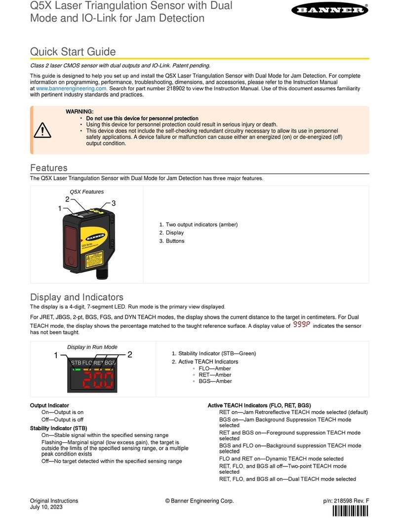
Q5X Laser Triangulation Sensor with Analog
Outputs and IO-Link Quick Start Guide
•
•
•
•
•
•
•
•
•
•
•
•
•
Product Description
LasersensorwithananalogoutputandIO-Link
ThisguideisdesignedtohelpyousetupandinstalltheQ5X Laser Triangulation Sensor.Forcompleteinformationonprogramming,perfor-
mance,troubleshooting,dimensions,andaccessories,pleaserefertotheInstructionManualatwww.bannerengineering.com. Search for p/
n219602toviewtheInstructionManual.Useofthisdocumentassumesfamiliaritywithpertinentindustrystandardsandpractices.
WARNING:
Do not use this device for personnel protection
Using this device for personnel protection could result in serious injury or death.
Thisdevicedoesnotincludetheself-checkingredundantcircuitrynecessarytoallowitsuseinpersonnelsafe-
ty applications. A device failure or malfunction can cause either an energized (on) or de-energized (off) output
condition.
Features
TheQ5X Laser Triangulation Sensorhasthreemajorfeatures.
Q5XFeatures
1
23
Display and Indicators
Thedisplayisafour-digit,seven-segmentLED.Runmodeistheprimaryviewdisplayed.
For 1-PT, 2-PT, BGS, FGS, and DYN TEACH modes, the display shows the current distance to the target in centimeters. For Dual TEACH
mode,thedisplayshowsthepercentagematchedtothetaughtreferencesurface.Adisplayvalueof999Pindicatesthesensorhasnotbeen
taught.
DisplayinRunMode
STB 2-PT 1-PT MM
12
Output Indicators
Ch1: On when the displayed distance is within the taught
analogoutputwindow
Ch2: On when the displayed distance is within the taught
discreteoutputwindow
Stability Indicator (STB)
On—Stablesignalwithinthespecifiedsensingrange
Flashing—Marginalsignal,thetargetisoutsidethelimitsof
the specified sensing range, or a multiple peak condition
exists
Off—Notargetdetectedwithinthespecifiedsensingrange
Active TEACH Indicators (2PT and 1PT)
2-PTon—Two-pointTECHmodeselected(default)
1-PTon—One-pointTEACHmodeselected
Display Value Indicator (MM)
On—Displayshowsthedistanceinmillimeters(default)
Off—Displayshowstheanalogoutputvalue
ToggleofftheMMlightbypressingSELECTwhenthesen-
sor is in run mode. This changes the display to show the
analogoutputvalue.PressSELECTagaintoshowthedis-
tancevalue.
Twooutputindicators(amber)
1.
Display
2.
Buttons
3.
StabilityIndicator(STB—Green)
1.
◦
◦
Active TEACH Indicators
2-PT-Two-PointTEACH(Amber)
1-PT-One-PointTEACH(Amber)
2.
Displayvalueindicator(MM-Amber)
3.
© Banner Engineering Corp.

June 14, 2023page2
Q5X Laser Triangulation Sensor with Analog Outputs and IO-Link Quick Start Guide
•
•
•
•
•
•
•
•
•
•
•
•
•
•
•
•
•
•
Buttons
Usethesensorbuttons(SELECT)(TEACH),(+)(CH1/CH2),and(-)(MODE)toprogramthesensor.
Q5X sensor face
(SELECT)(TEACH)
PresstoselectmenuitemsinSetupmode
Pressandholdforlongerthan2secondstostartthecur-
rently selected TEACH mode (the default is two-point
TEACH)
(+)(CH1/CH2)
PresstonavigatethesensormenuinSetupmode
Press to change setting values; press and hold to increase
numericvalues
Pressandholdforlongerthan2secondstoswitchbe-
tweenChannel1andChannel2
(-)(MODE)
PresstonavigatethesensormenuinSetupmode
Press to change setting values; press and hold to decrease
numericvalues
Press and hold for longer than 2 seconds to enter Setup
mode
NOTE: When navigating the menu, the menu
itemsloop.
Class2LaserDescriptionandSafetyInformation
CAUTION:
Return defective units to the manufacturer.
Use of controls or adjustments or performance of procedures other than those specified herein may result in
hazardousradiationexposure.
Do not attempt to disassemble this sensor for repair. A defective unit must be returned to the manufacturer.
CAUTION:
Neverstaredirectlyintothesensorlens.
Laserlightcandamageyoureyes.
Avoid placing any mirror-like object in the beam. Never use a mirror as a retroreflective target.
For Safe Laser Use - Class 2 Lasers
Donotstareatthelaser.
Donotpointthelaserataperson’seye.
Mountopenlaserbeampathseitheraboveorbeloweyelevel,wherepractical.
Terminatethebeamemittedbythelaserproductattheendofitsusefulpath.
Class2lasersarelasersthatemitvisibleradiationinthewavelengthrangefrom400nmto700nm,whereeyeprotectionisnormallyafford-
edbyaversionresponses,includingtheblinkreflex.Thisreactionmaybeexpectedtoprovideadequateprotectionunderreasonablyfore-
seeableconditionsofoperation,includingtheuseofopticalinstrumentsforintrabeamviewing.
Low-power lasers are, by definition, incapable of causing eye injury within the duration of a blink (aversion response) of 0.25 seconds. They
also must emit only visible wavelengths (400 to 700 nm). Therefore, an ocular hazard may exist only if individuals overcome their natural
aversiontobrightlightandstaredirectlyintothelaserbeam.
© Banner Engineering Corp.

Q5X Laser Triangulation Sensor with Analog Outputs and IO-Link Quick Start Guide
June 14, 2023 page3
(1) Applying tilt to sensor may improve performance on reflective targets. The direction and magnitude of the tilt depends on the application, but a 15° tilt is often
sufficient.
Class2RedLasermodels:ReferenceIEC60825-1:2014
FDA (CDRH) warning label (Class 2)
LASER LIGHT
DO NOT STARE INTO BEAM
CLASS 2 LASER PRODUCT
IEC 60825-1:2014. Wavelength
640-670nm; 1.0mW max. Complies with
21 CFR 1040.10 and 1040.11 except for
conformance with IEC 60825-1: 2014
as described in Laser Notice
No. 56, dated May 8, 2019.
Output:<1.0mW
Laser wavelength:640to670nm
Pulse Duration:20µsto2ms
Installation
Sensor Orientation
Optimizedetectionreliabilityandminimumobjectseparationperformancewithcorrectsensor-to-targetorientation.Toensurereliabledetec-
tion,orientthesensorasshowninrelationtothetargettobedetected.
OptimalOrientationofTargettoSensor
See the following figures for examples of correct and incorrect sensor-to-target orientation as certain placements may pose problems for
sensingsometargets.TheQ5Xcanbeusedinthelesspreferredorientationandatsteepanglesofincidenceandstillprovidereliabledetec-
tion performance due to its high excess gain. For the minimum object separation distance required for each case, refer
to"TypicalPerformanceCurves" on page 10.
Orientationbyawall Orientation for a moving object Orientation for a height difference
Orientation for a color or luster difference
Horizontal
Orientation Orientation
(Optimal)
CC
Orientation for highly reflective target(1)
Reflective
Surface
(optional)
Mount the Device
Ifabracketisneeded,mountthedeviceontothebracket.
1.
© Banner Engineering Corp.

June 14, 2023page4
Q5X Laser Triangulation Sensor with Analog Outputs and IO-Link Quick Start Guide
Wiring Diagrams
Wiring diagram for 4-20mA Analog
shield
+
12–30VDC
D_Out/IO-Link
A_Out
Input
–
Load
* Push-Pull output. User-configurable PNP/NPN setting.
bu (3)
bn (1)
wh (2)
bk (4)
gy (5)
**
NPN
Wiring diagram for 0-10V Analog
shield
+
12–30VDC
D_Out/IO-Link
A_Out
Input
–
Load
* Push-Pull output. User-configurable PNP/NPN setting.
0-10 V
bu (3)
bn (1)
wh (2)
bk (4)
gy (5)
**
NPN
1
4
5
3
2
CleaningandMaintenance
Cleanthesensorwhensoiledandusewithcare.
Handle the sensor with care during installation and operation. Sensor windows soiled by fingerprints, dust, water, oil, etc. may create stray
light that may degrade the peak performance of the sensor. Blow the window clear using filtered, compressed air, then clean as necessary
using only water and a lint-free cloth.
Button Map from RSD1 to Sensor
The sensor may be optionally connected to the Banner RSD1 remote display accessory. Refer to this table for the RSD1 button association
withyoursensor.
Button association between the RSD1 and the Q4X/Q5X sensors
Device UpButton DownButton EnterButton EscapeButton
RSD1
Q4XandQ5X
N/A
SensorProgramming
Programthesensorusingthebuttonsonthesensorortheremoteinput(limitedprogrammingoptions).
Inadditiontoprogrammingthesensor,usetheremoteinputtodisablethebuttonsforsecurity,preventingunauthorizedoraccidentalpro-
grammingchanges.SeetheInstructionManual,p/n219602formoreinformation.
SetupMode
AccessSetupmodeandthesensormenufromRunmodebypressingandholdingMODEforlongerthan2seconds.Use+and-tonavi-
gatethroughthemenu.PressSELECTtoselectamenuoptionandaccessthesubmenus.Use+and-tonavigatethroughthesubmenus.
PressSELECTtoselectasubmenuoptionandreturntothetopmenu,orpressandholdSELECTforlongerthan2secondstoselectasub-
menuoptionandreturnimmediatelytoRunmode.
ToexitSetupmodeandreturntoRunmode,navigatetoEndandpressSELECT.
Thenumberthatfollowsamenuoption,forexampletch1,indicatesthechannelthatisselected.Formenuitemswithoutanumber(exclud-
ing submenu items), these menu options are only available from Channel 1 and the settings apply to both channels.
Mount the device (or the device and the bracket) to the machine or equipment at the desired location. Do not tighten the mounting
screwsatthistime.
2.
Checkthedevicealignment.
3.
Tightenthemountingscrewstosecurethedevice(orthedeviceandthebracket)inthealignedposition.
4.
© Banner Engineering Corp.

Q5X Laser Triangulation Sensor with Analog Outputs and IO-Link Quick Start Guide
June 14, 2023 page5
Sensor Menu Map—Channel1
© Banner Engineering Corp.

June 14, 2023page6
Q5X Laser Triangulation Sensor with Analog Outputs and IO-Link Quick Start Guide
SensorMenuMap—Channel2
Basic TEACH Instructions
UsethefollowinginstructionstoteachtheQ5Xsensor.Theinstructionsprovidedonthesensordisplayvarydependingonthetypeof
TEACHmodeselected.Two-pointTEACHisthedefaultTEACHmode.
© Banner Engineering Corp.
Q5X Laser Triangulation Sensor with Analog Outputs and IO-Link Quick Start Guide
June 14, 2023 page7
•
•
•
•
•
•
•
•
•
•
See the Instruction Manual for detailed instructions and other available TEACH modes. The TEACH modes include:
Two-pointanalogteach2-Pt—Setsthedistancevaluesassociatedwith0Vand10V(4mAand20mA)basedontaughttargetdis-
tances
Onepointanalogteach1-Pt—Setsthe5V(12mA)midpointoftheanalogoutputtocentertheanalogoutputaroundareferencetar-
getposition
Two-pointstaticbackgroundsuppression2-Pt(discrete,channel2only)—Two-pointTEACHsetsasingleswitchpoint.Thesensor
setstheswitchpointbetweentwotaughttargetdistances.
DynamicbackgroundsuppressiondYn(discrete,channel2only)—Dynamic TEACH sets a single switch point during machine run
conditions.Thesensortakesmultiplesamplesandtheswitchpointissetbetweentheminimumandthemaximumsampleddis-
tances.
One-pointwindow(foregroundsuppression)FGS(discrete,channel2only)—One-point window sets a window (two switch points)
centered around the taught target distance.
One-pointbackgroundsuppressionbGS(discrete,channel2only)—One-point background suppression sets a single switch point in
front of the taught target distance. Objects beyond the taught switch point are ignored.
Dualintensity+distanceduAL(discrete,channel2only)—Dualmoderecordsthedistanceandamountoflightreceivedfromtheref-
erencesurface.See"Dual Mode Reference Surface Considerations" on page 11formoreinformationaboutselectingareference
surface. The output switches when an object passing between the sensor and the reference surface changes the perceived distance
oramountofreturnedlight.
ManualAdjustments
Manuallyadjustthesensorswitchpointusingthe+and-buttons.
NOTE: WhenFGSmodeisselected,manualadjustmentmovesbothsidesofthesymmetricalthresholdwindowsimul-
taneously,expandingandcollapsingthewindowsize.Manualadjustmentdoesnotmovethecenterpointofthewin-
dow.
NOTE: When dual mode is selected, after the TEACH process is completed, use the manual adjustment to adjust the
sensitivityofthethresholdsaroundthetaughtreferencepoint.Thetaughtreferencepointisacombinationofthemea-
sured distance and returned signal intensity from the reference target. Manual adjustment does not move the taught
referencepoint,butpressing+increasesthesensitivity,andpressing-decreasesthesensitivity.Whenre-positioning
thesensororchangingthereferencetarget,re-teachthesensor.
Locking and Unlocking the Sensor Buttons
Usethelockandunlockfeaturetopreventunauthorizedoraccidentalprogrammingchanges.
Three settings are available:
—Thesensorisunlockedandallsettingscanbemodified(default).
—Thesensorislockedandnochangescanbemade.
—Theswitchpointvaluecanbechangedbyteachingormanualadjustment,butnosensorsettingscanbechangedthrough
themenu.
WhenthesensorisineitherLocor0Locmode,theactivechannelcanbechangedusing(+)(CH1/CH2).
WheninLocmode,Locdisplayswhenthe(SELECT)(TEACH)buttonispressed.Theswitchpointdisplayswhen(+)(CH1/CH2)or(-)
(MODE)arepressed,butLocdisplaysifthebuttonsarepressedandheld.
Whenin0Locmode,Locdisplayswhen(-)(MODE)ispressedandheld.Toaccessthemanualadjustoptions,brieflypressandre-
lease(+)(CH1/CH2)or(-)(MODE).ToenterTEACHmode,pressthe(SELECT)(TEACH)buttonandholdforlongerthan2seconds.
PressandholdTEACHforlongerthan2secondstostarttheselectedTEACHmode.
1.
Presentthetarget.
2.
PressTEACHtoteachthetarget.Thetargetistaughtandthesensorwaitsforthesecondtarget,ifrequiredbytheselectedTEACH
mode,orreturnstoRunmode.
3.
CompletethesestepsonlyifitisrequiredfortheselectedTEACHmode.
4.
Presentthesecondtarget.
a.
PressTEACHtoteachthetarget.ThetargetistaughtandthesensorreturnstoRunmode.
b.
FromRunmode,presseither+or-onetime.
Theselectedchanneldisplaysbriefly,thenthecurrentswitchpointvalueflashesslowly.
1.
Press+tomovetheswitchpointupor-tomovetheswitchpointdown.
After 1 second of inactivity, the new switch point value flashes rapidly, the new setting is accepted, and the sensor returns to Run
mode.
2.
© Banner Engineering Corp.

June 14, 2023page8
Q5X Laser Triangulation Sensor with Analog Outputs and IO-Link Quick Start Guide
ToenterLocmode,hold+andpress-fourtimes.Toenter0Locmode,hold+andpress-seventimes.Holding+andpressing-fourtimes
unlocksthesensorfromeitherlockmodeandthesensordisplaysuLoc.
Averaging
UsetheAveragingAUGmenutosetthenumberofmeasurementsthatareaveragedtogetherfortheanalogoutput.
Increasingtheaveragingimprovesrepeatability,butincreasesthetotalresponsespeed.Thedefaultis16.Thefiltercanbesetto1,2,4,8,
16,32,64,128,256,or512.Usethetabletodeterminethetotalresponsespeed.
Response Speed (ms)
Base Measurement
Rate
FilterSetting
1 2 4 8 16 32 64 128 256 512
0.5ms 0.5 1.5 3 7 13 26 50 100 200 400
1.0ms 1 3 5 11 20 45 90 160 320 650
2.0ms 3 5 9 20 40 80 150 300 600 1200
3.0ms 5 8 15 30 55 110 220 420 840 1680
5.0ms 10 15 25 45 85 170 340 680 1350 2270
Lateral Entry Response
Lateral entry to the Q5X Base Measurement
Rate(ms) LateralEntryResponse(ms)
0.5 3
1.0 5
2.0 15
3.0 25
5.0 50
When lateral entry needs to be considered, the lateral entry response is added to calculate the total response time.
NOTE: TheQ5Xusesadynamicmeasurementrate,sotheseresponsetimesareworst-case.
Specifications
Sensing Beam
IEC 60825-1:2014
VisibleredClass2lasermodels,650nm
Supply Voltage (Vcc)
12to30VDC(Class2supply)(10%maxripplewithinlimits)
Supply Protection Circuitry
Protected against reverse polarity and transient overvoltages
Power and Current Consumption, exclusive of load
< 1 W
Sensing Range
95mmto3000mm(3.74into118.11in)
Output Configuration
Channel 1: Analog output
Channel 2: Configurable PNP/NPN discrete output or IO-Link
Response Speed
Total response speed varies between 0.5 ms and 2270 ms,
dependingonbasemeasurementrateandaveragingset-
tings.
Formoreinformation,see"Averaging" on page 8.
Boresighting
± 65 mm at 3000 mm
Delay at Power Up
< 2.5 s
Maximum Torque
Sidemounting:1N·m(9in·lbs)
Ambient Light Immunity
5000luxat1m
2000luxat2m
Connector
Integral 5-pin M12 male quick-disconnect connector
Construction
Housing: ABS
Lens cover: PMMA acrylic
Lightpipe and display window: polycarbonate
Temperature Effect (Typical)
< 0.5 mm/°C at < 500 mm
<1.0mm/°Cat<1000mm
< 2.0 mm/°C at < 2000 mm
< 5.0 mm/°C at < 3000mm
© Banner Engineering Corp.

Q5X Laser Triangulation Sensor with Analog Outputs and IO-Link Quick Start Guide
June 14, 2023 page9
Remote Input
Allowable Input Voltage Range: 0 to Vsupply
ActiveHigh(internalweakpull-down):Highstate>(Vsupply–
2.25 V) at 2 mA maximum
Active Low (internal weak pull-up): Low state < 2.25 V at 2 mA
maximum
IO-Link Interface
IOLinkRevisionV1.1
Smart Sensor Profile: Yes
Baud Rate: 38400 bps
Process Data In Length: 32 bits
Process Data Out Length: 8 bits
Minimum Cycle Time: 3.6 ms
IODD files: Provides all programming options of the display,
plus additional functionality.
Application Note
For optimum performance, allow 10 minutes for the sensor to
warm up
Environmental Rating
IP67perIEC60529
Vibration
MIL-STD-202G, Method 201A (Vibration: 10 Hz to 55 Hz, 0.06
inch (1.52 mm) double amplitude, 2 hours each along X, Y
and Z axes), with device operating
Shock
MIL-STD-202G, Method 213B, Condition I (100G 6x along X,
Y, and Z axes, 18 shocks), with device operating
Operating Conditions
–10°Cto+50°C(+14°Fto+122°F)
35% to 95% relative humidity
Storage Temperature
–25°Cto+70°C(–13°Fto+158°F)
Excess Gain
Base
Mea-
sure-
ment
Rate
(ms)
Base
Mea-
sure-
ment
Rate in
Sync
Mode
(ms)
Ambi-
ent
Light
Rejec-
tion
ExcessGain(90%WhiteCard)
at 100
mm
at 500
mm
at
1000
mm
at
2000
mm
at
3000
mm
0.5 1.0 Dis-
abled 200 80 25 6 3
1.0 2.0 En-
abled 200 80 25 6 3
2.0 4.0 En-
abled 920 400 100 25 12
3.0 6.0 En-
abled 1600 700 200 50 25
5.0 10.0 En-
abled 3200 1400 400 100 50
Discrete Output Rating
Current rating: 50 mA maximum
Blackwirespecificationsperconfiguration
IO-Link Push/Pull
OutputHigh: ≥Vsupply-2.5V
OutputLow: ≤2.5V
PNP
OutputHigh: ≥Vsupply-2.5V
OutputLow: ≤1V(loads≤1MegΩ)
NPN
OutputHigh: ≥Vsupply-2.5V(loads≤50kΩ)
OutputLow: ≤2.5V
Whitewirespecificationsperconfiguration
Q5XKU...models 0–10VDC,1000Ohmminimum
Q5XKI...models 4–20mADC,300Ohmmaximum
DiscreteOutputDistanceRepeatability
Distance(mm) Repeatability
95to300 ±0.5mm
300to1000 ±0.25%
1000to2000 ±0.5%
2000to3000 ±1.0%
Beam Spot Size
x
yBeam
Spot
Pattern
Distance(mm) Size(x×y)(mm)
100 2.6×1.5
1000 4.2×2.5
2000 6×3.6
2000to3000 7.8×4.7
Beamspotsizeiscalculatedas1.6timestheD4σmeasured
value
© Banner Engineering Corp.

June 14, 2023page10
Q5X Laser Triangulation Sensor with Analog Outputs and IO-Link Quick Start Guide
Required Overcurrent Protection
WARNING: Electrical connections must
bemadebyqualifiedpersonnelinac-
cordancewithlocalandnationalelectri-
calcodesandregulations.
Overcurrentprotectionisrequiredtobeprovidedbyendprod-
uctapplicationperthesuppliedtable.
Overcurrent protection may be provided with external fusing
or via Current Limiting, Class 2 Power Supply.
Supply wiring leads < 24 AWG shall not be spliced.
For additional product support, go
towww.bannerengineering.com.
Supply
Wiring
(AWG)
Required Overcurrent
Protection (A)
Supply
Wiring
(AWG)
Required Overcurrent
Protection (A)
20 5.0 26 1.0
22 3.0 28 0.8
Continued on page 10
Continued from page 9
Supply
Wiring
(AWG)
Required Overcurrent
Protection (A)
Supply
Wiring
(AWG)
Required Overcurrent
Protection (A)
24 1.0 30 0.5
Certifications
Banner Engineering BV
Park Lane, Culliganlaan 2F bus 3
1831 Diegem, BELGIUM
Class2power;ULEnvironmentalRating:Type1
TypicalPerformanceCurves
Minimum Object Separation Distance (90% to 6% reflectance) for
the 3000 mm Models
Switch Point
Distance
Background
X
Y
Discrete Minimum Object Separation (Uniform and Non-Uniform)
Dimension X
0
10
20
30
40
50
60
70
80
90
100
0500 15001000 2000 2500 3000 3500
Matte targets with a non-uniform
reflectivity: 6% to 90%
Matte targets with uniform
reflectivity: 6% to 90%
Accuracy (90% to 6% Reflectance)
Accuracy ( ± mm)
25
0
5000 1000 1500 2000 2500 3000 3500
50
75
100
125
150
Repeatability (90% to 6% Reflectance)
Distance (mm)
Repeatability (±mm)
0500 1000 1500 2000 2500 3000 3500
0
5
10
15
20
25
30
Continued on page 11
© Banner Engineering Corp.
Q5X Laser Triangulation Sensor with Analog Outputs and IO-Link Quick Start Guide
June 14, 2023 page11
Continued from page 10
Temperature Effects (90% to 6% Reflectance)
0
1
0.5
2
3
4
5
0 500 1000 1500 2000 2500 3000 3500
Dual Mode Reference Surface Considerations
Optimizereliabledetectionbyapplyingtheseprincipleswhenselectingyourreferencesurface,positioningyoursensorrelativetotherefer-
encesurface,andpresentingyourtarget.
TherobustdetectioncapabilitiesoftheQ5Xallowssuccessfuldetectionevenundernon-idealconditionsinmanycases.Typicalreference
surfaces are metal machine frames, conveyor side rails, or mounted plastic targets. Contact Banner Engineering if you require assistance
settingupastablereferencesurfaceinyourapplication.
Fordetailedinstructionsfordetectingclearortransparentobjects,refertotheInstructionManual,p/n219602.
BannerEngineeringCorpLimitedWarranty
BannerEngineeringCorp.warrantsitsproductstobefreefromdefectsinmaterialandworkmanshipforoneyearfollowingthedateofship-
ment. Banner Engineering Corp. will repair or replace, free of charge, any product of its manufacture which, at the time it is returned to the
factory, is found to have been defective during the warranty period. This warranty does not cover damage or liability for misuse, abuse, or the
improperapplicationorinstallationoftheBannerproduct.
THISLIMITEDWARRANTYISEXCLUSIVEANDINLIEUOFALLOTHERWARRANTIESWHETHEREXPRESSORIMPLIED(INCLUD-
ING, WITHOUT LIMITATION, ANY WARRANTY OF MERCHANTABILITY OR FITNESS FOR A PARTICULAR PURPOSE), AND WHETHER
ARISING UNDER COURSE OF PERFORMANCE, COURSE OF DEALING OR TRADE USAGE.
ThisWarrantyisexclusiveandlimitedtorepairor,atthediscretionofBannerEngineeringCorp.,replacement.INNOEVENTSHALLBAN-
NER ENGINEERING CORP. BE LIABLE TO BUYER OR ANY OTHER PERSON OR ENTITY FOR ANY EXTRA COSTS, EXPENSES,
LOSSES, LOSS OF PROFITS, OR ANY INCIDENTAL, CONSEQUENTIAL OR SPECIAL DAMAGES RESULTING FROM ANY PRODUCT
DEFECT OR FROM THE USE OR INABILITY TO USE THE PRODUCT, WHETHER ARISING IN CONTRACT OR WARRANTY, STATUTE,
TORT, STRICT LIABILITY, NEGLIGENCE, OR OTHERWISE.
BannerEngineeringCorp.reservestherighttochange,modifyorimprovethedesignoftheproductwithoutassuminganyobligationsorlia-
bilitiesrelatingtoanyproductpreviouslymanufacturedbyBannerEngineeringCorp.Anymisuse,abuse,orimproperapplicationorinstalla-
tion of this product or use of the product for personal protection applications when the product is identified as not intended for such purposes
willvoidtheproductwarranty.AnymodificationstothisproductwithoutpriorexpressapprovalbyBannerEngineeringCorpwillvoidtheprod-
uct warranties. All specifications published in this document are subject to change; Banner reserves the right to modify product specifications
orupdatedocumentationatanytime.SpecificationsandproductinformationinEnglishsupersedethatwhichisprovidedinanyotherlan-
guage.Forthemostrecentversionofanydocumentation,referto:www.bannerengineering.com.
Forpatentinformation,seewww.bannerengineering.com/patents.
◦
◦
◦
Selectareferencesurfacewiththesecharacteristicswherepossible:
Matteordiffusesurfacefinish
Fixedsurfacewithnovibration
Drysurfacewithnobuild-upofoil,water,ordust
1.
Positionthereferencesurfacebetween200mm(20cm)andthemaximumsensingrange.
2.
Positionthetargettobedetectedasclosetothesensoraspossible,andasfarawayfromthereferencesurfaceaspossible.
3.
Anglethesensingbeamrelativetothetargetandrelativetothereferencesurface10degreesormore.
4.
© Banner Engineering Corp.
June 14, 2023page12
Q5X Laser Triangulation Sensor with Analog Outputs and IO-Link Quick Start Guide
FCC Part 15 Class A
This equipment has been tested and found to comply with the limits for a Class A digital device, pursuant to part 15 of the FCC Rules. These
limitsaredesignedtoprovidereasonableprotectionagainstharmfulinterferencewhentheequipmentisoperatedinacommercialenviron-
ment.Thisequipmentgenerates,uses,andcanradiateradiofrequencyenergyand,ifnotinstalledandusedinaccordancewiththeinstruc-
tion manual, may cause harmful interference to radio communications. Operation of this equipment in a residential area is likely to cause
harmfulinterferenceinwhichcasetheuserwillberequiredtocorrecttheinterferenceathisownexpense.
IndustryCanadaClassA
This device complies with CAN ICES-3 (A)/NMB-3(A). Operation is subject to the following two conditions: 1) This device may not cause
harmfulinterference;and2)Thisdevicemustacceptanyinterferencereceived,includinginterferencethatmaycauseundesiredoperation.
Cet appareil est conforme à la norme NMB-3(A). Le fonctionnement est soumis aux deux conditions suivantes : (1) ce dispositif ne peut pas
occasionner d'interférences, et (2) il doit tolérer toute interférence, y compris celles susceptibles de provoquer un fonctionnement non
souhaité du dispositif.
Documenttitle:Q5XLaserTriangulationSensorwithAnalogOutputsandIO-LinkQuickStartGuide
Partnumber:219603
Revision:C
OriginalInstructions
©BannerEngineeringCorp.Allrightsreserved.
219603
© Banner Engineering Corp.
Other manuals for Q5X
12
Table of contents
Other Banner Security Sensor manuals

Banner
Banner L-GAGE LTF12 User manual

Banner
Banner EZ-SCREEN User manual

Banner
Banner SLLVE23-350 User manual

Banner
Banner PVS28 Series User manual

Banner
Banner Q5X User manual

Banner
Banner VS8LEJ User manual

Banner
Banner EZ-SCREEN LS User manual

Banner
Banner ES-UA-5A User manual

Banner
Banner Q45 User manual

Banner
Banner K30 Pro User manual

Banner
Banner LTF Series User manual

Banner
Banner Q5X User manual

Banner
Banner SLLE14-280 User manual

Banner
Banner LS2e30-300Q8 User manual

Banner
Banner EZ-SCREEN SLSP14-450Q88 User manual

Banner
Banner ES-FA-9AA User manual

Banner
Banner SX5 User manual

Banner
Banner LTF User manual

Banner
Banner Q5X User manual