manuals.online logo
Brands
  1. Home
  2. •
  3. Brands
  4. •
  5. Baumer
  6. •
  7. Accessories
  8. •
  9. Baumer FVDK 10P65Y0/KS35A User manual

Baumer FVDK 10P65Y0/KS35A User manual

10138548
Í?*-uPÂÂ*Â?Î
1/4
Canada
Baumer Inc.
CA-Burlington, ON L7M 4B9
Phone +1 (1)905 335-8444
China
Baumer (China) Co., Ltd.
CN-201612 Shanghai
Phone +86 (0)21 6768 7095
Denmark
Baumer A/S
DK-8210 Aarhus V
Phone +45 (0)8931 7611
France
Baumer SAS
FR-74250 Fillinges
Phone +33 (0)450 392 466
Germany
Baumer GmbH
DE-61169 Friedberg
Phone +49 (0)6031 60 07 0
India
Baumer India Private Limited
IN-411038 Pune
Phone +91 20 2528 6833/34
Italy
Baumer Italia S.r.l.
IT-20090 Assago, MI
Phone +39 (0)2 45 70 60 65
Singapore
Baumer (Singapore) Pte. Ltd.
SG-339412 Singapore
Phone +65 6396 4131
Sweden
Baumer A/S
SE-56133 Huskvarna
Phone +46 (0)36 13 94 30
Switzerland
Baumer Electric AG
CH-8501 Frauenfeld
Phone +41 (0)52 728 1313
United Kingdom
Baumer Ltd.
GB-Watchfield, Swindon, SN6 8TZ
Phone +44 (0)1793 783 839
USA
Baumer Ltd.
US-Southington, CT 06489
Phone +1 (1)860 621-2121
www.baumer.com/worldwide
Baumer Electric AG · CH-8501 Frauenfeld
Phone +41 (0)52 728 1122 · Fax +41 (0)52 728 1144
FVDK 10P65Y0/KS35A
Optoelektronische Sensoren
Photo electric sensors
Cellules opto-électroniques
Lichtleitergerät
Fiber optic sensor
Cellules pour fibres
optiques
Abmessungen
Dimensions
Dimensions
Technische Änderungen vorbehalten Technical specifications subject to change Sous réserve de modifications techniques
Allg. Sicherheitsbestimmungen
General safety instructions
Instructions générales de sécurité
•Die Angaben des Sicherheitskonzeptes und die Einsatzgrenzen der Verkaufsdokumentation sind zu beachten.
•Safety concept information and limiting parameters as published in the sales documentation apply at all times.
•Les caractéristiques pour les consignes de sécurité ainsi que les paramètres de montage sont à respecter et à contrôler avec l a documentation de vente.
•Vor dem Anschliessen des Sensors die Anlage spannungsfrei schalten.
•Disconnect power before connecting the sensor.
•Mettre l`installation hors tension avant le raccordement dela cellule optoélectronique.
Elektrischer Anschluss
Connection diagram
Schéma de raccordement
BN = braun/brown/brun
BK = schwarz/black/noir
BU = blau/blue/bleu
PK = rosa/pink/rose
0 V
PNP light/dark
+VS
Z
Ext. Teach
BN
PK
BK
BU
4,2
22,5 16
12,4 35,3
1,5
32,4
28,4
4
ø 3,3
7,6
8,4
0,5
10
13,7
200
M8 x 1
7
max. 34
Anschlussbelegung
Pin assignment
Raccordement
1 / +VS3 / 0 V
4 / light/dark
2 / Ext. Teach
All manuals and user guides at all-guides.com
2/4
FVDK 10P65Y0/KS35A
Technische Daten
Technical data
Données techniques
Betriebsreichweite (Einweg) Actual range Sb (through beam) Portée de fonctionnement Sb (barrière)
T
astweiteT
w (Reflex-Lic
htleiter) Sensing distance
T
w (diffuse sensor) P
ortéeT
w (réflex)
Betriebsspannungsbereich Vs V
oltage supply range
Vs Plage de tension
Vs
max. Stromverbrauc
hmax. supply current Consommation max.
max. Sc
haltstrom max. switching current Courant de sortie max
Spannungsabf
all V
oltage drop T
ension résiduelle
Ansprechzeit Response time T
emps d'activation
Abfallz
eit Release time T
emps désactivation
Kurzsc
hlussfest Short circuit protection Protégé contre courts-circuits
V
erpolungsfest Reverse polarity protectionProtégé contre inversion polarité
Betriebstemperatur T
emperature range T
empérature de fonctionnement
Sc
hutzklasse Protection class Classe de protection
Montage und Justage
Mounting
Montage
Anderes Ende nach unten drücken und einrasten.
Zum Herausnehmen den Hebel mit einem flachen
Schraubendreher etwas herausziehen.
Befestigen Sie das Licthleitergerät mit dem beiliegenden
Montagewinkel oder einer DIN - Schiene.
Ein Ende der Aussparung an der einen Seite des Winkels
oder der DIN-Schiene einhaken.
Mount the amplifier on the original bracket (attached to the
amplifier) or the DIN rail.
Engage the (A) part shown below to one rail of the original
bracket or the DIN rail.
Push the (B) part downwards until it clicks.
To remove the amplifier, use a standard screwdriver to pull
the (C) part backwards and lift it up.
Pressez "B" vers le bas jusqu'au clic.
Pour libérer la cellule, insérez un tournevis et pressez "C" vers
l' extérieur
Fixez la cellule pour fibres optiques à l'aide de l'étrier de montage
inclut ou sur rail DIN..
Enclenchez d' abord la partie (A) de la cellule sur l' équerre ou
sur le rail DIN.
A
BC
DIN-Schiene
A
BC
rail DIN
A
BC
DIN rail
540 mm (with FSE 200C1Y00)
150 mm (with FLE 200C1Y00)
10 - 30 VDC (ripple 1
0% max.)
50 mA
100 mA
< 1 VDC max.
500 msmax.
500 msmax.
ja/ yes/ oui
ja/ yes/ oui
-20° to +55°C
IP 40
All manuals and user guides at all-guides.com
3/4
FVDK 10P65Y0/KS35A Lichtleitergerät/ fiber optic sensor/ cellules pour fibres optiques
Empfindlichkeitseinstellung:
Die folgende Konfiguration ist bei Anlieferung eingestellt:
- Modus Schalter auf RUN, Hell-/Dunkelschaltung auf L-ON,
maximale Empfindlichkeit
n
oi
t
c
ur
ts
ni'
d
le
u
na
M
la
una
m
r
es
U
g
n
u
tielnas
g
n
u
neideB
Sensitivity adjustment
Following mode is set when the product is delivered:
- Mode selector on RUN, light-on/dark-on selector on L-ON (light-on),
max. sensitivity
Component description
Die Bedienelemente
Anzeige aktivierte
Ausgansverzögerungszeit
TUNING - Taste
L-ON/D-ON Schalter
- L
-ON=Hellschaltung
- D-ON=Dunkelschaltung
Modus Schalter RUN/SET
7 - Segment-
anzeige
Verschmutzungs-
anzeige (grüne LED)
Ausgangsanzeige
(red LED)
Hintergrund
Objekt
Einstellung für Kontrasterkennung
1. Führen Sie einen entsprechenden Lichtleiter in den Sensor ein.
2. Stellen Sie den Modus-Schalter auf "SET".
Display: 1 (grüne LED=aus; rote LED=aus)
3. Das Objekt in die gewünschte Position bringen und die TUNING-Taste
drücken.
Display: 2
(Genügend Signalreserve: rote LED=aus; grüne LED=blinkt
Ungenügend Signalreserve: rote LED=blinkt; grüne LED=blinkt)
4. Das Objekt entfernen. Anschliessend die TUNING-Taste drücken.
Korrekte Einstellung: Fehlerhafte Einstellung:
Empfindlichkeitsanzeige 1 bis 9.
(Bedeutung der Werte siehe
nächste Seite, unten!)
Stellen Sie den Modus-Schalter
auf "RUN". Einstellung fertig.
Um ein Objekt neu einzulernen,
den Modus-Schalter auf "SET"
stellen und den Programmier-
vorgang von 2 - 4 wiederholen.
- "E" blinkt wenn das Objekt
ausserhalb des Bereiches ist.
- "E" leuchtet, wenn der Kontrast-
unterschied zu gering ist.
Der Sensor funktioniert nicht, wenn
bei fehlerhafter Einstellung in den
"RUN" Modus gewechselt wird!
Ändern Sie die Objektposition und
wiederholen Sie den Programmier-
vorgang 2 - 4.
background
mark
Contrast detection setting
1
. Put a fiber cable into the sensor.
2. Set mode selector to "SET" mode.
Digital display: 1 (green LED=off; red LED=off)
3. Put a target on ideal sensing position and press TUNING button once.
Digital display: 2
(sufficient sensitivity: red LED=off; green LED=flashing
insufficient sensitivity: red LED=flashing; green LED=flashing)
4. Take the target away and press TUNING button once again.
correct tuning: incorrect tuning:
- "E" flashes when sensitivity is
insufficient
- "E" lights on when the contrast
is not clear enough
Change the position of your object
and/or the sensing distance and
repeat the procedure from 2 to 4.
Note: The sensor will not operate
if the mode is changed to "RUN" mode
with an incorrect tuning status.
Sensitivity margin indicates 1 to 9
(The meaning of this value is
explained on the next page!)
Set mode selector to "RUN".
Contrast detection setting is now
adjusted.
If a new setting is necessary,
set Mmode selector to "SET" and
repeat the programming procedure
2 to 4.
OFF - delay display
TUNING button
L
-ON/D-ON selector
- L
-ON=light on
- D-ON=dark on
Mode selector RUN/SET
Digital display
Stability indicator
(green LED)
Operating indicator
(red LED)
Réglage de sensibilité
La produit est livré avec la configuration suivant:
- Sélecteur de mode "RUN", commutateur L-ON/D-ON sur mode L-ON
(commutation claire) et sensibilité réglée au maximum.
Description des éléments de réglage
objet
arrière-plan
Détection de contraste
1
. Introduisez la fibre choisie dans les orifices de la cellule.
2. Mettre le sélecteur de mode sur "SET"
Affichage digital: 1 (LED verte=off; LED rouge=off)
3. Mettre le premier objet en position. Pressez la touche TUNING.
Affichage digital: 2
(Lumière suffisante: LED rouge=off; LED verte=clignote
Lumière insuffisante: LED rouge=clignote; LED verte=clignote)
4. Enlever l'objet. Pressez à nouveau la touche TUNING.
Fonction correcte: Fonction incorrecte:
- "E" clignote si la lumière est
insuffisant.
- "E" allumé si le contraste est
insuffisant.
Essayez de rapprocher la fibre de
l'objet.
Renouvelez la procédure de
2 à 4. La cellule ne fonctionne pas
si, lors d'un mauvais réglage, l'on
commute en mode "RUN".
Marge de contraste 1 à 9.
(Pour information sur marge de
contraste, visitez la dernièr page!)
Remettre le sélecteur de mode
sur "RUN".
Pour l'ajustage sur un nouvel
objet, commutez le contact sur
"SET" et renouvelez la
procédure de 2 à 4.
Affichage pour la temporisation
à la retombée
Bouton TUNING
Sélecteur L-ON/D-ON
- L-ON=commutation claire
- D-ON=comutation sombre
Sélecteur de mode RUN/SET
Affichage digital
Témoine de service
LED vert
Témoin de commutation
(LED rouge)
All manuals and user guides at all-guides.com
4/4
FVDK 10P65Y0/KS35A Lichtleitergerät/ fiber optic sensor/ cellules pour fibres optiques
User manual Manuel d'instruction
Bedienungsanleitung
correct tuning: incorrect tuning:
Red LED=off; green LED=flashing Red & green LED=flashing
- "E" flashes when sensitivity is
insufficient
Change the position of your object
and/or the sensing distance and
repeat the procedure from 2 to 3.
The sensor will not operate if the
mode is changed to "RUN"mode
with an incorrect tuning status.
Set mode selector to "RUN".
Contrast detection setting is now
adjusted.
If a new setting is necessary,
set mode selector to "SET" and
repeat the programming procedure
2 to 3.
Positions - Einstellung
1. Führen Sie einen entsprechenden Lichtleiter in den Sensor ein.
2. Modus - Schalter auf "SET" stellen.
Display: 1 (grüne LED=aus; rote LED=aus)
3. Objekt in die gewünschte Position bringen und TUNING-Taste drücken.
Display: 2
Korrekte Einstellung: Fehlerhafte Einstellung:
Rote LED=aus; grüne LED=blinkt Rote & güne LED=blinken
Stellen Sie den Modus-Schalter
auf "RUN". Einstellung fertig.
Um ein Objekt neu einzulernen,
den Modus-Schalter auf "SET"
stellen und den Programmier-
vorgang von 2 - 3 wiederholen.
- "E" blinkt wenn das Objekt
ausserhalb des Bereiches ist.
Ändern Sie die Objektposition und
wiederholen Sie den Programmier-
vorgang 2 - 3. Der Sensor
funktioniert nicht, wenn bei fehler-
hafter Einstellung in den "RUN"
Modus gewechselt wird!
Position setting
1. Put a fiber cable into the sensor.
2. Set mode selector to "SET" mode.
Digital display: 1 (green LED=off; red LED=off)
3. Put a target on ideal sensing position and press the TUNING button once.
Digital display: 2
Indication de la sensibilité - valeur limite.
La limite de la sensibilité est indiquée sitôt que la procédure d'
ajustage est terminée.
Affichage de la marge 1 2 3 4 5 6 7 8 9
Facteur de sécurité >1.0 >1.2 >1.5 >2.0 >3.0 >4.0 >5.0 >6.0 >7.0
Temporisation à la retombée
Pour activer ou désactiver la temporisation à la retombée, le sélecteur
de mode doir être en position "RUN" (marche). Pressez le bouton
TUNING pendant 10s. L'activation on/off est indiqué par un point rouge.
(Point rouge allumé=temporisation à la retombée de 40ms est activé)
Puissance maximale
1. Mettre le sélecteur de mode sur "SET".
Affichage digital: 1 (LED verte=off; LED rouge=off)
2. Appuyer sur le bouton TUNING pendant 3s.
Affichage digital: H (LED verte=on; LED rouge=on)
3. Remettre le sélecteur de mode "RUN". La puissance maximale est
ainsi obtenue.
Fonction correcte: Fonction incorrecte:
LED rouge=off; LED verte=clignote LED rouge & verte=clignote
- "E" clignote si la lumière est
insuffisant.
Essayez de rapprocher la fibre
de l'objet.
Renouvelez la procédure de
2 à 3. La cellule ne fonctionne
pas si, lors d'un mauvais réglage,
l'on commute en mode "RUN".
Remettre le sélecteur de mode
sur "RUN".
Pour l'ajustage sur un nouvel
objet, commutez le contact sur
"SET" et renouvelez la
procédure de 2 à 3.
Détection de position
1. Introduisez la fibre choisie dans les orifices de la cellule.
2. Mettre le sélecteur de mode sur "SET".
Affichage digital: 1 (LED verte=off; LED rouge=off)
3. Mettre le bord de l'objet en position. Pressez la touche TUNING.
Affichage digital: 2
Abfallverzögerung - Einstellung
Die Abfallverzögerung wird aktiviert wenn der Sensor im "RUN" -
Modus ist und die TUNING-Taste länger als 10s gedrückt wird. Ob
die Abfallverzögerung aktiv ist oder nicht, sieht man am roten Punkt.
(Roter Punkt leuchtet=Ausgansverzögerung von 40ms aktiv)
Bei einer Verpolung der Versorgungsspannung leuchten alle 6 LED's
auf dem Display auf ("0" - Darstellung) und blinken.
Einstellung der maximalen Empfindlichkeit
1. Stellen Sie den Modus - Schalter auf "SET".
Display: 1 (grüne LED=aus; rote LED=aus)
2. Drücken Sie jetzt die Teach-in-Taste länger als 3s.
Disaply: H (grüne LED=leuchtet; rote LED=leuchtet)
Stellen Sie nun den Modus - Schalter auf "RUN" zurück. Die maximale
Empfindlichkeit ist nun eingestellt.
Empfindlichkeitsanzeige - Grenzbereich
Der Empfindlichkeits-Grenzbereich wird als Zahl auf dem Display
angezeigt, sobald die Programmiervorgang abgeschlossen ist.
Empfindlichkeit 1 2 3 4 5 6 7 8 9
(7 - Segmentanzeige)
Sicherheitsfaktor >1.0 >1.2 >1
.5 >2.0 >3.0 >4.0 >5.0 >6.0 >7.0
Sensitivity margin indication
Sensitivity margin will be indicated when sensitivity adjustment is over.
Sensitivity (digital display) 1 2 3 4 5 6 7 8 9
Contrast value as
automatically settled hysteresis >1
.0 >1
.2 >1.5 >2.0 >3.0 >4.0 >5.0 >6.0 >7.0
When short circuit protection is activating, each LED of 6 LED's
for "0" flashes and turns clockwise. When this happens, correct wiring.
Off delay setting
Off delay function can activate when mode selector is on "RUN" mode
and tuning button is pressed for longer than 10 sec.
Activation/disactivation of off delay function is shown by red dot.
(Red point is on=Off delay of 40ms is activated!)
Une inversion de la polarité est indiquée par le fait que les 6 LD's
clignotent et par l' affichage du "0". Corrigez dans ce cas le câblage.
Externes teach-in
Die Programmierung der Kontrasterkennung kann über den Eingang
ext. Teach erfolgen. Der Programmierablauf erfolgt identisch der
Einstellung für die Kontrasterkennung mittels TUNING Taste.
Folgen Sie diesem Ablauf. (vorige Seite)
PNP: Ein kurzer Impuls von 24 VDC am Eingang ext. Teach
bewirkt dasselbe wie ein Druck auf die TUNING Taste im Normal-
betrieb.
La programmation de la reconnaissance de contraste peut se réaliser
avec l'entrée teach- externe. La procédure est similaire à celle réalisée
avec la touche TUNING.
Suivez la procédure ( page précédente).
PNP: Une courte impulsion de 24 VDC sur l'entrée teach-externe
produit le même effet qu'une pression sur la touche TUNING
en mode normal.
Teach-in-externe
Remote teach-in
For external programming of the contrast detection, you can use the
ext. teach input. The programming process is similar the teach-in
procedure with the TUNING button.
Follow the procedure "contrast detection setting" on the site before.
PNP: A short 24 VDC pulse on the ext. teach input is similar with a
push on the TUNING button in the normal mode.
Maximum sensitivity setting
1. Set mode selector to "SET" mode.
Digital display: 1 (green LED=off; red LED=off)
2. Press tuning button for longer than 3 second.
Digital display: H (green LED=on; red LED=on)
Put mode selector to "RUN" mode. Maximum sensitivity setting is over.
All manuals and user guides at all-guides.com

Other Baumer Accessories manuals

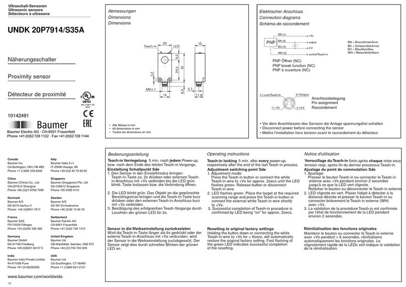
Baumer UNDK 20P7914/S35A User manual

Baumer

Baumer UNDK 20P7914/S35A User manual

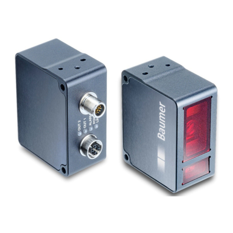
Baumer OX200 User manual

Baumer

Baumer OX200 User manual

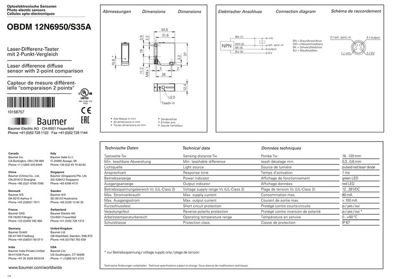
Baumer OBDM 12N6950/S35A User manual

Baumer

Baumer OBDM 12N6950/S35A User manual

Baumer UNDK 10N8914/KS35A User manual

Baumer

Baumer UNDK 10N8914/KS35A User manual

Baumer UNDK 10P8914/KS35A User manual

Baumer

Baumer UNDK 10P8914/KS35A User manual

Baumer R600V.DAH5 User manual

Baumer

Baumer R600V.DAH5 User manual

Baumer OADM 12U6460/S35A User manual

Baumer

Baumer OADM 12U6460/S35A User manual

Baumer UNAR 18P7903/S14G User manual

Baumer

Baumer UNAR 18P7903/S14G User manual

Baumer UNAM 12P3912/S14 User manual

Baumer

Baumer UNAM 12P3912/S14 User manual

Baumer CombiFlow PF75H User manual

Baumer

Baumer CombiFlow PF75H User manual

Baumer UNAM 12P1912/S14 User manual

Baumer

Baumer UNAM 12P1912/S14 User manual

Baumer OADM 21I6480/S14F User manual

Baumer

Baumer OADM 21I6480/S14F User manual

Baumer UNDK 20P7914/S35A User manual

Baumer

Baumer UNDK 20P7914/S35A User manual

Baumer UNAM 12N1912/S14 User manual

Baumer

Baumer UNAM 12N1912/S14 User manual

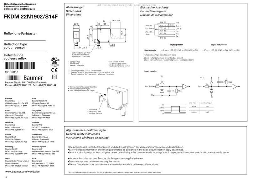
Baumer FKDM 22N1902/S14F User manual

Baumer

Baumer FKDM 22N1902/S14F User manual

Baumer qTarget OT500 User manual

Baumer

Baumer qTarget OT500 User manual

Baumer OHDM 16N5651 User manual

Baumer

Baumer OHDM 16N5651 User manual

Baumer UNAM 18P7903/S14 User manual

Baumer

Baumer UNAM 18P7903/S14 User manual

Baumer UNAR 18P6912/S14G User manual

Baumer

Baumer UNAR 18P6912/S14G User manual

Baumer OADM 20I6581/S14F User manual

Baumer

Baumer OADM 20I6581/S14F User manual

Baumer UNAM 12N3914/S14 User manual

Baumer

Baumer UNAM 12N3914/S14 User manual

Baumer FEDK 07N6901/KS35A User manual

Baumer

Baumer FEDK 07N6901/KS35A User manual

Baumer UNAM 18P7903/S14 User manual

Baumer

Baumer UNAM 18P7903/S14 User manual

Baumer FKDM 22P1902/S14F User manual

Baumer

Baumer FKDM 22P1902/S14F User manual

Popular Accessories manuals by other brands

Clas Ohlson HTD58667A-F instruction manual

Clas Ohlson

Clas Ohlson HTD58667A-F instruction manual

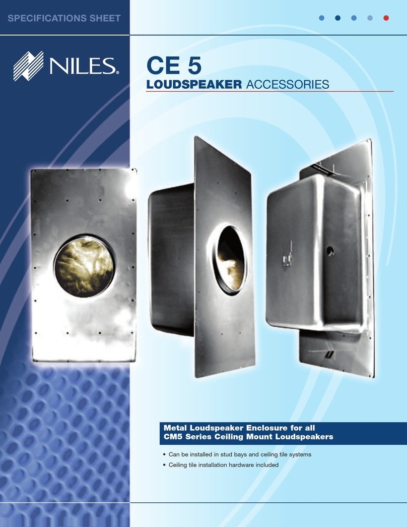
Niles CE 5 Specifications

Niles

Niles CE 5 Specifications

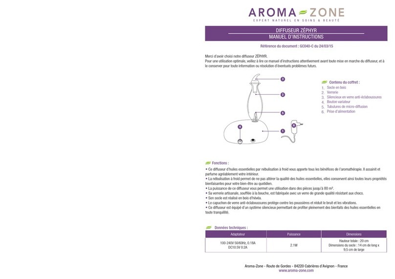
Aroma-Zone ZÉPHYR instruction manual

Aroma-Zone

Aroma-Zone ZÉPHYR instruction manual

Amcrest SmartHome AD410 Installing

Amcrest

Amcrest SmartHome AD410 Installing

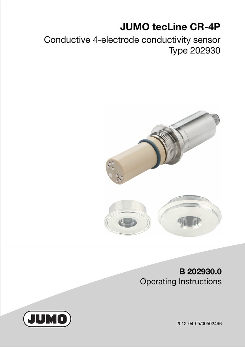
JUMO tecLine CR-4P operating instructions

JUMO

JUMO tecLine CR-4P operating instructions

ReFleX Wireless RX901a instruction manual

ReFleX Wireless

ReFleX Wireless RX901a instruction manual

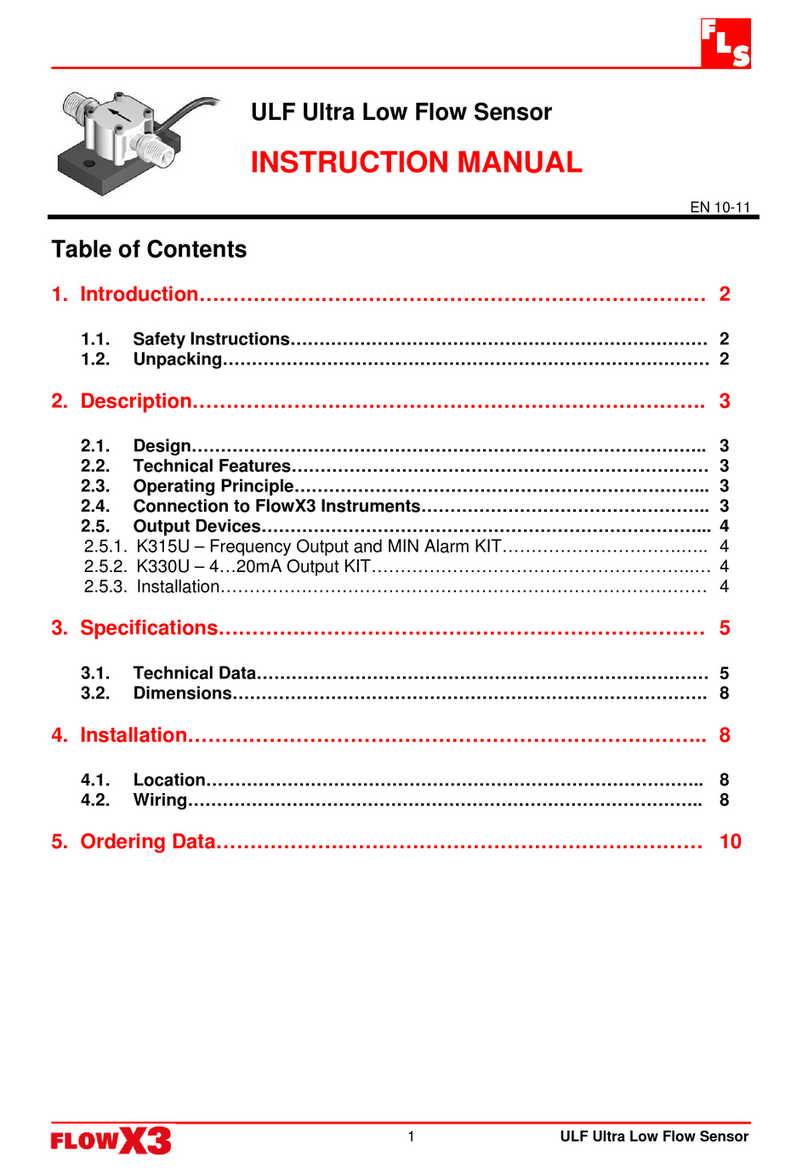
FLS FlowX3 series instruction manual

FLS

FLS FlowX3 series instruction manual

AAON AA-EBUS-DRS-TGD-01K Technical guide

AAON

AAON AA-EBUS-DRS-TGD-01K Technical guide

Panasonic MA3S781D Specification sheet

Panasonic

Panasonic MA3S781D Specification sheet

Carefree MARQUEE owner's manual

Carefree

Carefree MARQUEE owner's manual

Konifera BW73002 Assembly instructions

Konifera

Konifera BW73002 Assembly instructions

DISTINQ DQEB11WT instruction manual

DISTINQ

DISTINQ DQEB11WT instruction manual

SICK MZT6-03VPS-KPX operating instructions

SICK

SICK MZT6-03VPS-KPX operating instructions

Vega VEGAPULS C 21 operating instructions

Vega

Vega VEGAPULS C 21 operating instructions

S&S Northern Merlin CO2 AVG Installation & operation manual

S&S Northern

S&S Northern Merlin CO2 AVG Installation & operation manual

LG Power Tank PMC-1000 user manual

LG

LG Power Tank PMC-1000 user manual

Hewi AQ1.12S21040 manual

Hewi

Hewi AQ1.12S21040 manual

Middle Atlantic Products ICOMP-COOL Quiet-Cool Series instruction sheet

Middle Atlantic Products

Middle Atlantic Products ICOMP-COOL Quiet-Cool Series instruction sheet

manuals.online logo
manuals.online logoBrands
  • About & Mission
  • Contact us
  • Privacy Policy
  • Terms and Conditions

Copyright 2025 Manuals.Online. All Rights Reserved.