BEA IS40P User manual

2
5
6
4
1
3
1
2
75.5696.02 EN 20120213 Page 1 of 8
DESCRIPTION SPECIFICATION
SENSOR TILT ANGLE 15° to 45°
SUPPLY VOLTAGE 12 to 24 VAC ±10%
12 to 24 VDC +30% / -5%
MAIN FREQUENCY 50 to 60 Hz
POWER CONSUMPTION < 2 W
RELAY OUTPUT
- Max. Voltage
- Max. Current
- Max Switching Power
2 Relays with switch-over contact (voltage free)
60 VDC / 125 VAC
1 A (resistive)
30 W (DC) / 60 VA (AC)
INSTALLATION HEIGHT 8 ft - 16 ft (2.5 m – 6 m)
TEMPERATURE RANGE -22°F ( -30°C) to + 140°F (60°C)
PROTECTION DEGREE IP65 / NEMA 4
NORM CONFORMITY Electromagnetic compatibility (EMC) according to 2004/108/EEC, R&TTE: 1999/5/EC
DIMENSIONS (D X W X H) 5 in × 4 in × 3.75 in (127 mm × 102 mm × 96 mm)
MATERIAL
- Housing
- Face
ABS
Polycarbonate
COLOR
- Housing
- Face
Black
Transparent Purple
CABLE LENGTH 32 ft (10 m)
TECHNOLOGY INFRARED
RADIATED FREQUENCY 875 nm
RADIATED POWER DENSITY < 250 mW/m²
DETECTION MODE Presence
MAXIMUM DETECTION FIELD 10 ft x 10 ft (3 m x 3 m)
OUTPUT HOLD TIME 0.5 s – 9 s (Activation Relay) / 0.5 s (Presence Relay)
REACTION TIME 250 ms
MINIMUM TARGET SPEED 0 in/s (0 cm/s)
LED SIGNAL Green = Activation Relay / Red = Presence Relay
SENSOR ANGLE 15°, 30°, 45°
IS40P
USER’S GUIDE
ACTIVE INFRARED (IR) PRESENCE SENSOR
IS40P
- The IS40P uses Active
Infrared technology for
presence detection.
SPECIFICATIONS
1. IR angle indicator
2. LED’s
3. IR emitters
4. Sensor angle adjustment
5. Bracket
6. Cable
DESCRIPTION

!
CAUTION
1 9/16
1 1/16
1 1/16 1 1/16
4 1/8
1/2
1 1/4
1 1/2
6
5
4
3
6
6.25
3
6.25
6
2.5
75.5696.02 EN 20120213 Page 2 of 8
PRECAUTIONS
This device IS NOT intended for use as a safety sensor.
Not recommended for dynamic envioronments. (snow, rain, fog, etc.)
Shut off all power before attempting any wiring procedures.
Maintain a clean & safe environment when working in public areas.
Constantly be aware of pedestrian/vehicle trafc around the area.
Always stop pedestrian/vehicle trafc through the doorway when performing tests that may result in unexpected reactions by the door.
ESD electrostatic discharge: Circuit boards are vulnerable to damage by electrostatic discharge. Before handling any board ensure
you dissipate your body’s charge.
Always check placement of all wiring before powering up to insure that moving parts will not catch any wires and cause damage to
equipment.
Ensure compliance with all applicable safety standards upon completion of installation.
DO NOT attempt any internal repair of the sensor. All repairs and/or component replacements must be performed by BEA Inc. Unau-
thorized disassembly or repair:
1. May jeopardize personal safety and may expose one to the risk of electrical shock.
2. May adversely affect the safe and reliable performance of the product and will result in a voided product warranty.
DIMENSIONS (inches)
MOUNTING
Wall mounting Ceiling mounting Bracket dimensions
INSTALLATION TIPS
The sensor must be
rmly fastened to
prevent vibration.
The sensor must not
have any object likely
to move or vibrate in
its sensing eld.
DO NOT cover
the sensor.
Remove the bracket from the sensor.
Drill 2 holes accordingly. If necessary, drill an additional
hole to facilitate wire routing. Fix the bracket rmly.
Position the sensor on the bracket
and fasten the angle adjustment screws.
Avoid exposing the
sensor to sudden
temperature changes
Avoid proximity to neon
lamps, uorescent lights
or moving objects

8
7
4
8
12
16
20
ft
ft
63 0 36
DOOR
4
8
12
16
20
ft
ft
63 0 36
DOOR
4
8
12
16
20
ft
ft
63 0 36
DOOR
75.5696.02 EN 20120213 Page 3 of 8
WIRING AND RELAY CONFIGURATION
Notes:
1. It is important to adjust sensor angle to position IR eld correctly.
2. To obtain an IR pattern that’s straight down (closest to the door threshold); wall mounted sensors need to be
set at 20º; sensors mounted on an extension bracket or out from the wall should be set to approximately 15º.
3. The graphics above are not to scale and for illustration purposes and represent an approximate IR detection
field when at 16 ft. The point of emphasis is to show the IR detection area with respect to the sensor angles.
SENSOR ANGLE
COM
NO
NC
RED
BLACK
12-24 V
AC-DC
WHITE
GREEN
YELLOW
WHITE/BLACK
GREEN/BLACK
YELLOW/BLACK
COM
NO
NC
Red LED
Presence
1-4
Activation
Relay
Presence
Relay
1 Active Passive
2 Passive Active
3 Passive Passive
4 Active Active
Description Active Passive
Detection COM COM
No
Detection COM COM
NO
NC
NO
NC
NO
NC
NO
NC
RELAY
CONFIGURATION
WIRING
Adjust the angle of the sensor to position the detection eld Tighten the screws rmly
RECOMMENDED
SPECIAL APPLICATIONS
CEILING
WALL
15° 30° 45°
ACTIVATION RELAY
PRESENCE RELAY
POWER
RECOMMENDED
Green LED
Presence

9
12”
A
B
C
D
E
75.5696.02 EN 20120213 Page 4 of 8
* Dimensions are approximate.
Approximate default IR pattern size using a 15º sensor tilt angle.
The higher the mounting height the larger the IR pattern.
SENSOR
IR PATTERN SIZE AT 15° SENSOR ANGLE
Mounting
Height
Width * Depth *
A = 8 ft 5 ft 5 ft
B = 10 ft 7 ft 7 ft
C = 11.5 ft 7.5 ft 7.5 ft
D = 13 ft 8.5 ft 8.5 ft
E = 16 ft 10 ft 10 ft
Maximum Mounting Height
IS40P 16 ft
Use of BEA Spotnder may be
utilized to locate IR eld.

10
75.5696.02 EN 20120213 Page 5 of 8
OUTPUT CONFIGURATION
OUTPUT
CONFIGURATION
PRESENCE RELAY IS40P LED
0 – 6: ALL MODES Activates when object is in presence zone.
ACTIVATION RELAY IS40P LED
0: STANDARD MODE Activates when object is in presence zone
1: PULSE ON ENTRY Activates when object enters presence zone
2: PULSE ON EXIT Activates when object exits presence zone
3: PULSE ON ENTRY FIRST / LAST LINE
(See Example to the Left)
Activates when object enters presence zone
(rst or last line)
4: PULSE ON EXIT FIRST / LAST LINE
(See Example to the Left)
Activates when object exits presence zone
(rst or last line)
5: REMAINS ACTIVE UNTIL PRESENCE
ZONE IS CLEARED
Activates when object is in presence zone
6: REMAINS ACTIVE UNTIL PRESENCE
ZONE IS CLEARED
Activates when object is in presence zone
DOOR EXAMPLE
REMOTE CONTROL PARAMETERS
Red
FIRST LINE
LAST LINE
1
02 3 4 5 6 78 9
FREQUENCY
AUTOMATIC
LEARN TIME
IR IMMUNITY low medium high
1 min 2 min30 s 10 min 20 min5 min 1 h 2 h1.5 h
IR / Presence Settings
low high
∞
FACTORY
VALUES
=
Note:The automatic learn time is the amount of time a static
object needs to be in the IR eld before the sensor will learn it.
1 s 2 s
.5 s 4 s 5 s3 s 6 s 8 s7 s 9 s
ACTIVATION RELAY
HOLD TIME
Green

10 REMOTE CONTROL PARAMETERS (CONTINTUED)
DOOR
DOOR
DOOR
DOOR
DOOR
DOOR
DOOR
DOOR
DOOR
2
3
7
5
6
2
5
6
5
2
1
7
5
1
1
1
2
1
7
5
2
1
7
5
2
1
5
2
3
4
7
5
6
1
2
3
4
7
5
6
1
75.5696.02 EN 20120213 Page 6 of 8
FACTORY
VALUES
=
IR / Presence Settings (Continued)
IR PATTERN
SIZE
AVAILABLE TARGET SIZE
1
2
3
4
5
9
8
7
6
The target (Target Size)
can vary location within
the eld (IR Pattern Size)

10
x
11
New
Value
Parameter
75.5696.02 EN 20120213 Page 7 of 8
QUESTION A VALUE The number of green ashes
indicates the value of the
chosen parameter.
Check parameter values
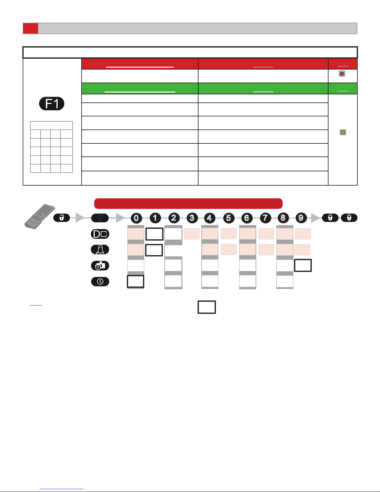
REMOTE CONTROL PARAMETERS (CONTINUED)
SENSOR SETUP SEQUENCE / FACTORY VALUES / ACCESS CODE
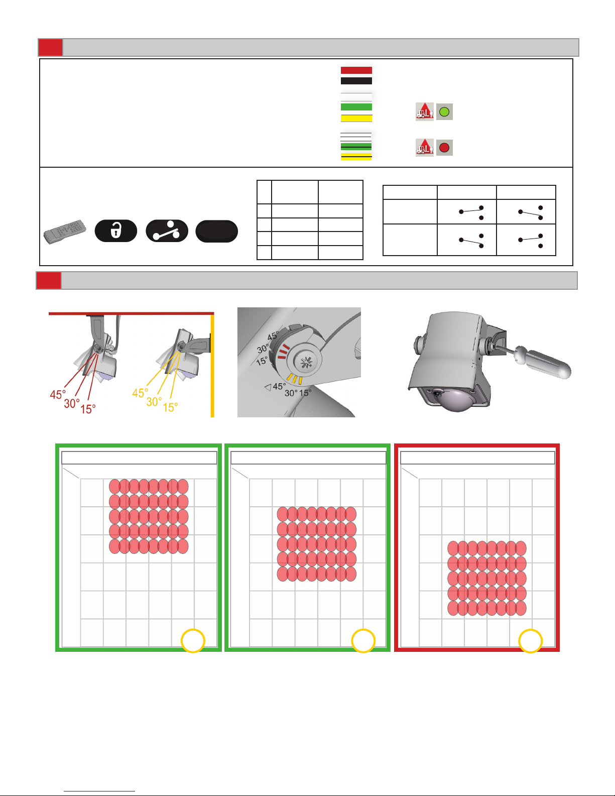
IMPORTANT: ALWAYS FINISH AN ADJUSTMENT
SESSION BY LAUNCHING A SETUP.
IMPORTANT: ENSURE TO SAVE ANY
CHANGES DURING THE ADJUSTMENT
SESSION VIA PRESSING LOCK LOCK.
RESETTING TO FACTORY VALUES
SETTING AN ACCESS CODE
DELETING AN ACCESS CODE
If you do not know the access code, cycle the power supply.
Within 1 minute, you can access the sensor without introducing any access code or delete the existing access code per the instrucitons above.
12 TROUBLESHOOTING
SYMPTOMS POSSIBLE CAUSES CORRECTIVE ACTION
The red LED is on during rain or
snow.
The presence detection is disturbed
by the rain or snow.
Increase the immunity of the IR eld.
(value 2 or 3 respectively).
The red LED is permanently on
after a setup.
Setup has failed due to motion in the
IR eld during setup.
Launch a setup with the IR area clear of
moving objects.
The door keeps recycling open
or closed.
The sensor detects door vibrations
or environmental disturbances.
Increase IR immunity.
Secure mounting bracket.
The door never closes and the
red LED is on. Objects in the IR detection area.
Wait for learn time to expire and/or
Launch a setup.
Move objects or reduce automatic learn
time.
The door never closed and the
LED(s) is off.
Output relay(s) could be wired or
congured backwards.
Change wiring at output(s) and/or
change relay conguration.

12
1
4
7
F1 F2
5
8
0
+
?
3
6
9
2 A
B
C
D
13
14
75.5696.02 EN 20120213 Page 8 of 8
Application requires an access
code or sensor will not unlock
after entering an access code.
You must enter a code or the wrong
code was entered.
Cycle the power. No code is required
to unlock during the rst minute after
powering on. Unlock, then lock and enter
a new access code or “0000” to delete
the current access code.
TROUBLESHOOTING (CONTINUED)
SYMPTOMS POSSIBLE CAUSES CORRECTIVE ACTION
The sensor does not respond to
the remote control.
The batteries in the remote control
are not installed properly, dead or the
remote is poorly aimed.
Verify or replace batteries or aim remote
towards sensor.
The sensor is not powered. Check the power supply of the sensor.
ACCESSORIES
Spotnder
P/N: 10SPOTFINDER
Remote control
P/N: 10REMOTE
Telescoping HD Bracket
P/N: 10HDBRACKET
COMPANY CONTACT
Our Service Technicians can be called 24 hours a day, 7 days a week. For more information visit www.beasensors.com.
Do not leave problems unresolved. If a satisfactory solution cannot be achieved after troubleshooting
a problem, please call BEA, Inc. If you must wait for the following workday to call BEA, leave the door
inoperable until satisfactory repairs can be made. Never sacrifice the safe operation of the automatic
door or gate for an incomplete solution.
After Normal Business Hours
West / Mexico
1-888-419-2564
Central
1-800-407-4545
AK, MI, WI, TX, Canada
1-866-836-1863
East
1-866-249-7937
Phone: 1-800-523-2462 Fax: 1-888-523-2462
Transformer
P/N: 1024VAC
Table of contents
Other BEA Accessories manuals

BEA
BEA SUPERSCAN-T User manual

BEA
BEA MAGIC SWITCH MS21H User manual

BEA
BEA VIO-D User manual

BEA
BEA PBR45 Series User manual

BEA
BEA BODYGUARD III GT 300 User manual

BEA
BEA C8 User manual

BEA
BEA LZR RS300 User manual

BEA
BEA 1SAFE User manual

BEA
BEA MAGIC SWITCH CHROMA User manual

BEA
BEA LZR SIGMA User manual