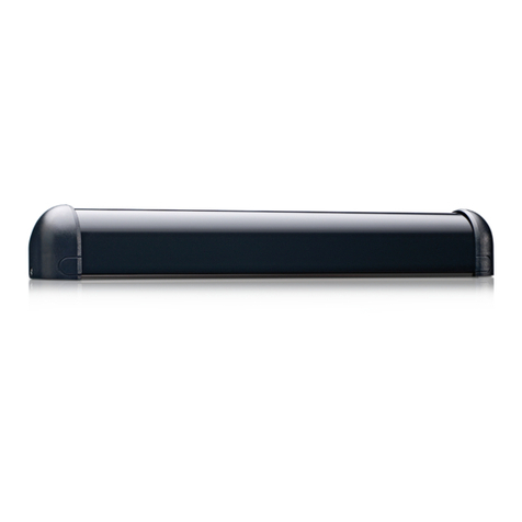
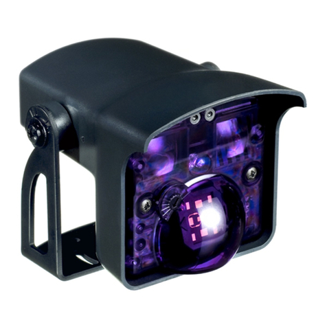
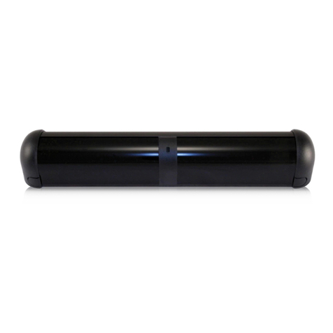
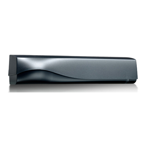
BEA DK-12 User manual

DK-12
PRESENCESENSOR
INSTRUCTIONMANUALFORINDUSTRIALAPPLICATIONS
We can be reached from anywhere in the world:
US & Canada Toll Free 800-523-2462 (EST)
US & Canada Toll Free 877-232-9378 (PST)
Mexico Toll Free 001-800-711-1398
Latin America 412-782-5191
B.E.A., Inc. •300 South Main Street •Pittsburgh PA 15215 •USA
Tel. 412-782-5150 •Fax 412-782-5154
75.1034 V1 Feb 2001
OBSOLETE

75.1034 V1 Feb 2001 Page 2 of 9
DK-12PRESENCESENSOR
The DK-12 is an active infrared presence sensor which is used for activation or safety on all types industrial
doors (high speed doors, sliding doors, rolling steel, vertical lift, etc.). The DK-12 projects a pyramid shaped
pattern that extends to the floor. It will automatically adjust itself upon initial programming to compensate for
bright light, shiny floors, various colors of carpeting, etc. It also has a fine tuning adjustment to accomodate
the most extreme environments.
For smaller openings, the DK-12's pattern can be reduced by shutting off one or two of the four zones
available, making it ideal for narrow doors or areas. When a door opening is 8 feet or less, one DK-12 should
be used and when a door opening is greater than 8 feet, two DK-12 s’s should be used.
Because it is microprocessor driven, the DK-12 has the ability to be programmed and to adapt to changing
environments. When the immediate area around a doorway gets cluttered with items that should not be there
such as pallets, pallet jacks, garbage cans, etc., the DK-12 will see these unwanted objects and begin to
learn the object and resume normal operation after the preset time delay expires. This is known as self-
adaptation and is adjustable from 30 seconds to 25 minutes.
DK-12TECHNICALSPECIFICATIONS
Installation height 7’ to 14’ for Industrial Doors
Wide detection pattern 6’ W x 4’ D (see pattern chart)
Narrow detection pattern (center, left, right) 2.5’ W x 3.5’ D (see pattern chart)
Asymmetrical detection pattern (left, right) 4’ W x 4’ D (see pattern chart)
Mounting angle 20°- 26°- 32°
Power supply 12 - 24 V AC or DC +/- 10 %
Frequency 50 or 60 Hz
Energy Consumption 2 W
Output SPDT relay
Max. voltage - relay contacts 60 V DC - 125 V AC
Max. current - relay contacts 8 AMP - resistive
Max. Power supply 30 Watts(DC), 125 V (AC)
Hold time 1 to 10 seconds
Operating temperature -30°F to 131°F
Immunity Immune to electrical and radio frequency interference
Cable 3 feet of 6 conductor cable
Extra cable is available upon request for an additional cost
Weight 1 lb., 11 oz.
Dimensions 11 ¼" L x 2¼" D x 3" H
Material Aluminum & ABS plastic
Housing color Black
OBSOLETE

INSTALLINGTHESENSOR
**B.E.A. sensors, as with all automatic door equipment, should be set up and
inspected in accordance with applicable ANSI standards.
1. Unscrew the left end cover of the DK-12 sensor, and remove the mounting bracket from the sensor by
sliding it out. To do this, loosen the allen head screw as shown below.
2. Select a mounting position for the sensor. For door opening narrower than 8 feet, the sensor should be
centered in relation to the door opening. If the DK-12 is used on any door with an opening greater than
8’, it is highly recommended to use more than one DK-12. Pattern selections will depend on the door and
the mounting position. See the chart and diagram on the following pages for pattern selection.
For openings wider than 8’ and higher than 14’
See page 7 for selecting the pulsing frequency of two
DK-12’s located next to each other
For openings narrower than 8’ and lower than 14’
75.1034 V1 Feb 2001 Page 3 of 9
*NOTE: Be sure that there are no objects within the view of the sensor lenses, such as a door roll.
DK-12
DK-12
DK-12
OBSOLETE

3. The mounting bracket may be mounted directly to a wall or to the ceiling above the door. Select the
location for mounting and secure solidly with screws provided.
Wall
Mount Ceiling
Mount
4. The installer must provide means for routing wires from the sensor to the inside of the header. The
terminal block is located at the left end of the sensor. At the back edge of the left and right end covers,
there is a small punch out slot to allow the concealed passage of wire into the sensor. A slot is also
provided at the top of the sensor, should wires need to be routed from the opposite end of the sensor.
Locate the wire passage hole on the header to keep it concealed. Once the hole is located and drilled,
pull the 6-conductor wire from the header to the sensor, and leave a few inches hanging out.
There is no need to drill holes in the aluminum mounting bracket. (voids warranty)
5. Mount the sensor back into its bracket as indicated below. The 20°position is considered standard.
6. Tighten set screw on sensor.
IMPORTANT NOTE: BEA strongly recommends the use of the WHU (weather protection hood) on any
DK-12 that is installed outside and is exposed to the elements. The circuit board of the DK-12 is not
waterproof; therefore, it is susceptible to water damage. Any DK-12 that is returned due to water
damage will be considered out of warranty.
WIRINGTHESENSOR
At the left side of the sensor, remove the 7 pin terminal connector by pulling it straight out. Connect wires as
shown below.
75.1034 V1 Feb 2001 Page 4 of 9
TOP VIEW OF CONNECTOR
Data wires are not used in
industrial applications
Setup
Button
IR
Receiver
Data (+)
Data (-)
NCNO
COM
24 V AC
OBSOLETE

DETECTORADJUSTMENTS–OPERATIONOFREMOTECONTROL
All adjustments to the DK-12 will be made by BEA’s infrared (IR) remote control. The IR remote control
enables one to set-up and adjust the detector. The remote uses a modified code, which makes it
incompatible with the majority of consumer electronics. Because the end cap blocks the IR receiver after
installation, no access code is required.
To adjust the DK-12, stand to the left of the detector, pointing the remote towards the left side of the detector
(without end cap installed) at a distance less than 6 feet from the DK-12. Each adjustment requires pushing
two buttons on the remote; a “function” button and then a number. Certain buttons are not used by the DK-12
and if they are pushed, will be ignored.
When one of the “function” buttons is pressed, the indicator LED on the detector will flash rapidly. The
flashing of the LED will only occur if a function button is pushed. During the flashing, the detector is waiting
for the input of a value between 0 and 9 for its setting. If a value is not entered within 20 seconds after
pressing one of the “function” buttons, the detector will go back to the previous settings and the LED will stop
flashing. In order to continue with another try, the whole cycle must be started again. For certain functions,
not all 10 digits (0-9) are available and if an error is made, the command is ignored and the adjustment must
be redone with proper values.
The remote provides access to all the adjustments of the detector:
SENSITIVITY
RELAY HOLD TIME
RELAY MODE
AUTO LEARN TIME
PATTERN
FREQUENCY
SINGLE OR DOUBLE SET-UP
INQUIRY FOR THE ABOVE SETTINGS ?
75.1034 V1 Feb 2001 Page 5 of 9
12
3
4
5
6
7
8
9
F
1
0
F
2
+
?
OBSOLETE

DK-12PROGRAMMING
The DK-12 has been programmed with factory default settings. They are defined on the remote control chart
on the following page. Please review the factory default settings before making any changes to the DK-12. If
at any time the factory default settings are appropriate for your application, you DO NOT have to change
them. Only change the parameters that are needed to customize your application.
To program the DK-12, complete the following steps:
1. Review the default settings.
2. Determine which settings need to be changed.
3. Change any setting that is independent of the door position (relay hold time, relay mode, auto learn,
frequency):
•Remove left end cap.
•Stand within 6’ of the left side of the sensor (do not be afraid to stand in the pattern area, but move
out of the pattern after making a change).
•Point the remote control toward the opening (the receiver is located inside of DK-12)
•Press the function button followed by the number that corresponds to the desired setting.
4. Launch a set-up with the followed by #1. This will enable the DK-12 to evaluate its surroundings and
store it into permanent memory. The LED will flash for approximately 10 sec. and stop once the set-up is
complete (see set-up for more details).
SET-UP
Once a set-up is launched the LED will flash at 5 Hz for approximately 10 seconds.
•If the set-up is successful, the LED will go off and the detector will function normally.
•If the set-up is not successful, the LED will continue to flash, but at a lower frequency of 2.5 Hz.
•Possible problems during setup:
a. If a person walks through the detection zone during the set-up, the set-up can be
disturbed
b. If a very reflective object is placed within 32 inches from the DK-12, it can blind the
detector and make the set-up impossible.
c. If the set-up that corresponds to the DOOR OPEN state is launched when the door is
closed, the set-up will be ignored and vice versa.
Please note: When two DK-12’s are installed on the same door, place the end cap on one DK-12 and
program the open DK-12. Once the first DK-12 is programmed, install its end cap and remove the
second DK-12’s end cap and repeat the programming procedure.
75.1034 V1 Feb 2001 Page 6 of 9
OBSOLETE

Function
Buttons Actions Factory
Settings LED Status
SENSITIVITY – Press this key followed by the number
button (0-9) of the sensitivity desired. This setting can be
selected for both states of the door, DOOR OPEN or
DOOR CLOSED.
9 – maximum
0 - minimum
SEE section A on following page for more details.
Door closed = 8
Door open = 7
LED flashes
RELAY HOLD TIME – Press this key followed by the
number button (0-9) to enter the required hold time.
0- 1 sec. 4- 5 sec. 7- 8 sec.
1- 2 sec. 5- 6 sec. 8- 9 sec.
2- 3 sec. 6- 7 sec. 9- 10 sec.
3- 4 sec.
1 second = 0 LED flashes
PATTERN SELECTION – Press this key followed by a
number button (1-6) to select the required pattern. This
setting can be selected for both states of the door, DOOR
OPEN or DOOR CLOSED.
1- Wide pattern (ABCD)
2- Wide left pattern (ABC)
3- Wide right pattern (BCD)
4- Narrow left pattern (AB)
5- Narrow center pattern (BC)
6- Narrow right pattern (CD)
SEE section C on following page for more details.
Door closed = 1
Door open = 1
LED flashes
RELAY CONFIGURATION - Press this key followed by
a number button (1-4) to select the required relay output
desired.
1- active output, relay contact open during detection,
closed during non-detection
2- passive output, relay contact closed during detection,
open during non-detection
3- continuous detection, relay contact always closed
4- continuous non-detection, relay contact always open
Passive = 2 LED flashes
AUTO LEARN TIME – Press this key followed by a
number button (1-9) to select the required auto learn time.
0 – 30 sec. 4 – 5 min. 7 – 15 min.
1 – 1min. 5 – 7 min. 8 – 20 min.
2 – 2 min. 6 – 10 min. 9 – 25 min.
3 – 3 min.
SEE section B on following page for more details
1 minute = 1 LED flashes
FREQUENCY –Press this key followed by a number
button (1-2) to select the required frequency.
1 – high impulse
2 – low impulse
High impulse = 1
LED flashes
INQUIRY – Press this button after pressing the button of
the parameter that you would like to check. Then count the
number of times the LED flashes. This corresponds to the
status of the parameter in question.
No setting LED will flash
according to
the setting of
the parameter
in question.
SET-UP – Press this button followed by a number button
(1-3) to launch the desired set-up.
1 – Door closed set-up
2 – Door open set-up
3 – Reset factory default settings (can be pressed in either
door open or door closed position)
No setting See SET-UP
procedure.
?
75.1034 V1 Feb 2001 Page 7 of 9
OBSOLETE

SENSITIVITY
The sensitivity setting of the DK-12 allows the installer to adjust the size of the pattern selected for both states
of the door (DOOR OPEN or DOOR CLOSED).
The sensitivity of the pattern can be different when the door is open and when it is closed. In the DK-12,
there is no link between the pattern for DOOR OPEN or DOOR CLOSED. The sensitivity of the pattern is
accessible as a function of the state of the door and only the corresponding sensitivity can be adjusted. The
DK-12 receives communication from the LO-21 or SS-21 as to the state of the door (open or closed) via the
data lines.
•The maximum sensitivity is strongly discouraged for DOOR OPEN if the mounting height is less
than 8’.
•The sensitivity can be adjusted after doing a set-up without relaunching a set-up.
AUTOLEARNTIME
The Auto Learn Time is the time in which the DK-12 will automatically learn any permanent changes in its
field of detection. This time delay begins counting down once a change in the detection zone occurs. If the
object is removed from the zone before the time delay has expired the DK-12 will not save it as part of its
memory. During the auto learn time the DK-12 will lock on and hold the door in either the open or closed
position for the set learn time. Once the auto learn time has expired the DK-12 will do a short reevaluation
that takes +/- 10 seconds. If someone walks through the pattern during this evaluation, it will fail and the DK-
12 will stay triggered until it has a stable background to learn. After the DK-12 has learned the object, it will
resume its normal function.
•If the pattern of the DK-12 is interrupted during the auto learn time, the auto learn time will
continue to count down without interruption.
PATTERNSELECTION
The DK-12 detection zone is made up of 4 small zones placed next to each other, perpendicular to the door.
The 4 zones are shown in the diagram below. There are 6 different patterns with combinations of 4 detection
zones.
The shape of the pattern can be different when the door is open and when it is closed. In the detector, there
is no link between the pattern for the open door and the pattern for the closed door. The shape of the pattern
is accessible as a function of door state and only the corresponding shape can be adjusted. The DK-12
receives input from the LO-21 or SS-21 as to the state of the door via the data lines.
75.1034 V1 Feb 2001 Page 8 of 9
Header
DK-12
Width
ABCD
Depth
NOTE: After any change in the shape of the pattern, it is necessary to complete a set up.
OBSOLETE

75.1034 V1 Feb 2001 Page 9 of 9
DK-12TROUBLESHOOTINGGUIDE
DK-12 LED flashes very slowly and door remains open or closed
•Relay is in fixed ON position. Select a relay output of active or passive.
DK-12 LED flashes very slowly and door has no safety
•Relay is in the fixed OFF position. Select a relay output of active or passive.
DK-12 LED flashes very fast
•DK-12 has only received the first half of a two button remote input. Enter second half of code or wait 20
seconds for LED to go out.
•If LED fails to go out, power the DK-12 down and then power it back up.
DK-12 LED Flashes at a medium speed (4 flashes per second)
•DK-12 is programming. Stay out of the DK-12’s field of view.
DK-12 LED flashes at 1 flash per second
•DK-12 has failed to program due to interference during programming. Clear the pattern area and
reprogram.
•If DK-12 fails to program again, place a black mat on the floor in the DK-12’s field of view and reprogram.
Once programmed, remove the mat and let the DK-12 self adapt for the set Auto Learn Time.
If after troubleshooting a problem, a satisfactory solution cannot be achieved, please call B.E.A., Inc.
for further assistance during Eastern Standard Time at
1-800-523-2462 from 7am - 5pm or 1-800-407-4545 from 5pm - midnight & weekends.
DO NOT leave any problem unresolved. If you must wait for the following workday to call B.E.A.,
leave the door inoperable until satisfactory repairs can be made. NEVER sacrifice the safe
operation of the automatic door or gate for an incomplete solution.
OBSOLETE
Other manuals for DK-12
2
Table of contents
Other BEA Accessories manuals

BEA
BEA COLIBRI ONE DRO User manual

BEA
BEA Eagle 10 User manual

BEA
BEA CONDOR ID User manual

BEA
BEA MS21H User manual

BEA
BEA Jamb Style PBJ Series User manual

BEA
BEA Iris Overhead Safety for Door User manual

BEA
BEA Superscan User manual

BEA
BEA IS40 User manual

BEA
BEA IS40 User manual

BEA
BEA ACTIV8 THREE PULSE User manual