17
Emergency Reserve Manifold
2005715.05
When the ERM is in operation there is provision for
an alarm output to warn when the running bank
contents is typically below half. The ERM contents
gauge should then be locally monitored. The Bank
valves can be used to cycle the left and right banks
allowing for empty cylinders to be changed while
keeping continues supply to the pipeline.
CAUTION: The following procedures
4.2 to 4.7 are only typical guides, where there
areconictswiththehospital’semergency
procedure,thehospital’spolicieswilltake
precedence.
4.2 Procedure to prime ERM.
4.2.1 The following procedure must be carried
out once the commissioning (section 3) is complete
and the system is ready to be put into use.
4.2.2 Ensure the high-pressure isolation valve
on the left-hand bank is fully open, the right-hand
bank isolation valve is closed, and all cylinder
valves on both banks are fully closed. Correct as
required, see section 4.7 Cylinder Operation.
4.2.4 Ensure the connecting pipeline is ready for
use. Slowly open the line valve ‘B’ (Item 9, gure
1).
4.3 Procedure when mains sup-
ply fails.
4.3.1 The following steps relate to gure 1 & 2,
and detail how to operate the ERM in the event of
the main supply system failing to supply gas at the
correct distribution pressure.
4.3.2 Ensure the ERM line valve ‘B’ is open. Close
main supply line valve (Shown as valve ‘A’ in gure
2).
4.3.3 Ensure that one of the high-pressure
bank isolation valve is fully open, the other bank
isolation valve is closed, and all cylinder valves on
both banks are fully closed. Correct as required.
4.3.4 The pressure regulator will be set below
the nominal distribution system pressure. This
should now be increased to the full distribution
pressure by increasing the line regulator setting,
until the correct distribution pressure can be
obtained.
4.3.5 Once the ERM is in operation there is
provision for an alarm output to warn when the
running bank contents is typically below half.
The ERM contents gauge should then be locally
monitored for cycling the cylinder banks for
continuous supply (see section 4.4 for bank cycling
procedure).
4.4 Procedure to cycle banks &
changing cylinders.
4.4.1 Refer to hospitals/site policy for safe
cylinder handling (See section 4.6 for typical
cylinder handling safety check list) when moving
the cylinders into place ready for connection to the
tailpipes.
4.4.2 When the running bank pressure falls to
the pressure for changing cylinder (for typical
changeover pressures see table 5). Slowly open the
standby bank isolation valve (see gure 1). With
the standby bank now operating as the running
bank, close the high pressure isolation valve and
cylinder valves for the empty cylinder bank.
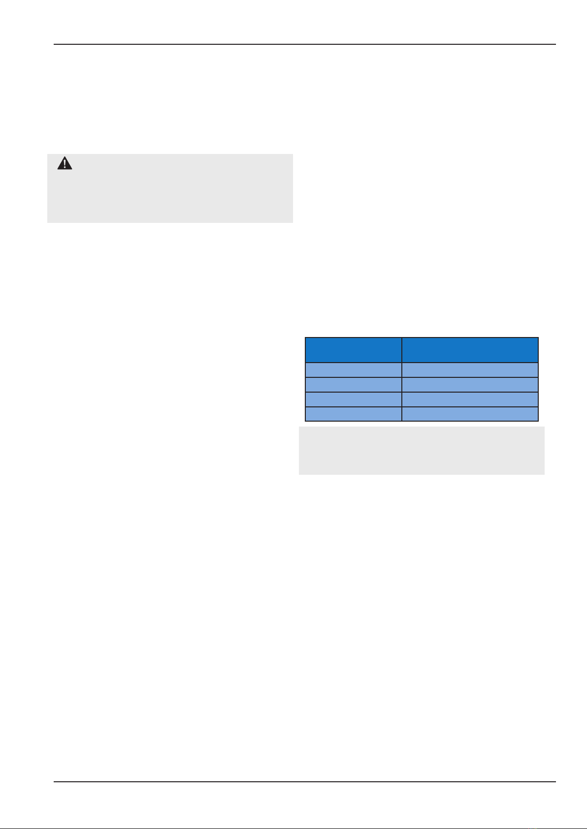
Table 4: Typical cylinder bank changeover
pressure.
Nominal Supply
pressure
Typical Cylinder changeover
4 Bar 15 Bar (50 Bar Cyl. and Below)
4 Bar 20 Bar (137 Bar Cyl. and above)
7 Bar 30 Bar
11 Bar 30 Bar
Note - Values in table 5 are only for reference
as a typical guide, refer to hospital emergency
procedure policy.
4.4.3 For the empty cylinder/s disconnect the
tailpipe from the cylinder (see gure 13) by either
undoing the handwheel or unscrewing the nut
at the cylinder end, depending on the cylinder
connection type.
4.4.4 Replace the empty cylinder/s and reconnect
the tailpipes. Slowly open the cylinder valves (see
section 4.7 - Cylinder operation.
4.4.5 Repeat this section each time the running
bank drops to the changeover pressure until the
main supply is fully operational.
4.5 Procedure to reinstate main
supply.
4.5.1 The following steps detail how to reinstate
the mains supply once it has been returned to
normal operation.
4.5.2 Slowly open valve ‘A’ (See gure 2).
4.5.3 Complete the steps in section 3, followed by
4.2