manuals.online logo
Brands
  1. Home
  2. •
  3. Brands
  4. •
  5. YOKOGAWA
  6. •
  7. Test Equipment
  8. •
  9. YOKOGAWA CA11E HANDY CAL User manual

YOKOGAWA CA11E HANDY CAL User manual

IM CA11E-02E <Page 1>
■ Calibration the Generation Feature
Operation procedure:
<1> Warm up the standard.
<2> Before turning on the power of the CA11E calibrator, connect it to the standard.
<3> Turn on the power of the instrument.
<4> Simultaneously press and hold the keys (shown in the gure in the
“Assignment of Keys for Calibration” section below) for about 2 seconds to enter
the calibration mode.
<5> Select the generation range to calibrate using the MEASURE/SOURCE selection
switch and range selection rotary switch. The display unit shows “CAL,” “SOURCE,”
“ON,” “0,” and the lower limit.
<6> Read the output value of the CA11E using the standard (digital multimeter), and using
the adjustment keys adjust the CA11E so that the output value is set to the offset
value. Then press and hold the input determination (ENTER) key for about 1 second
to x the setting.
After xing the setting, the display unit reading changes to “CAL,” “SOURCE,” “ON,”
“FS,” and a full scale of the range.
<7> Read the output value of the CA11E using the standard (digital multimeter), and using
the adjustment keys adjust the CA11E so that the output value is set to the full
scale value. Then press and hold the input determination (ENTER) key for about
1 second to x the setting.
After xing the setting, the display unit shows “0 FS” blinking. Re-press and hold
the input determination (ENTER) key for about 1 second to write the calibration
coefcients to the EEPROM of the instrument.
(This overwrites the previous calibration coefcients.)
When this is complete, the instrument returns to the status in Step 5.
<8> Repeat Steps 5 to 7 for each range to be calibrated.
To return to the previous step:
<9> To return to the previous step without xing the setting, press and hold the input
cancellation key for about 1 second.
Note that this is possible only before writing to the EEPROM.
To return to the nomal operation mode:
<10> Simultaneously press and hold the keys (shown in the gure in the
“Assignment of Keys for Calibration” section below) for about 2 seconds, or press
the [POWER] key to turn off the power once and then press it again to turn it back on.
■ Calibration Precautions
Connection for 20 mA SINK calibration
Connect the CA11E calibrator to the standard as show below:
CA11E
H
L
SINK
Lo Hi
DMM
current range
Constant-voltage
power supply
(Vo: 5 to 28 V)
■ Assignment of Keys for Calibration
When the CA11E calibrator is in the calibration mode, keys are assigned as specied here.
1 2 3 4
CAL
ON
SOURCE 0
Input cancellation key
Input determination
(ENTER) key
Digit to adjusted by
the adjustment keys
Mode switching
(calibration or nomal)
(Press and hold two keys
simultaneously for 2 seconds.)
Adjustment keys
(six keys)
(For about 1 second)
■ Calibration the Measurement Feature
Operation procedure:
<1> Warm up the standard.
<2> Before turning on the power of the CA11E calibrator, connect it to the standard.
<3> Turn on the power of the instrument.
<4> Simultaneously press and hold the keys (shown in the gure in the
“Assignment of Keys for Calibration” section below) for about 2 seconds to enter
the calibration mode.
<5> Select the measurement range to calibrate using the MEASURE/SOURCE
selection switch and range selection rotary switch.
“CAL” and “MEASURE” appear and “FS” blinks on the display unit.
(If a value nearly equivalent to full scale has been input, a measured value and
“FS” appear.)
<6> Set up the standard in order to input the full scale value to the instrument.
Wait until the reading stabilizes, then press and hold the input determination
(ENTER) key for about 1 second to x the setting.
<7> After xing the setting, “0” and “FS” indications on the display unit start blinking.
Re-press and hold the input determination (ENTER) key for about 1 second
to write the calibration coefcients to the EEPROM of the instrument.
(This overwrites the previous calibration coefcients.)
When this is complete, the instrument returns to the status in Step 5.
<8> Repeat Steps 5 to 7 for each range to be calibrated.
To return to the previous step:
<9> To return to the previous step without xing the setting, press and hold the input
cancellation key for about 1 second.
Note that this is possible only before writing to the EEPROM.
To return to the nomal operation mode:
<10> Simultaneously press and hold the keys (shown in the gure in the
“Assignment of Keys for Calibration” section below) for about 2 seconds, or press
the [POWER] key to turn off the power once and then press it again to turn it back on.
Safety Precautions
The following manual, including this manual, are provided as manuals for the CA11E.
Please be sure to read all manuals.
IM CA11E-03EN (Getting Started Guide: For Safety)
IM CA11E-01E (User's Manual - 1 - : Generation, Measurement, and Other features)
IM CA11E-02E (User's Manual - 2 - : Calibration procedure and Specication): This manual
8. Calibration Procedure
■ Calibration Procedure
To maintain a high level of accuracy, it is recommended that the CA11E HANDY CAL
be calibrated annually.
The “Selecting the Standards” section below presents calibration methods using the
recommended standards.
■ Selecting the Standards
<Source feature>
Items to be
calibrated Names of
standards Range Measuring
range Accuracy Remarks
DCV Digital
multimeter
(DMM)
100 mV
1000 mV
10 V
30 V
Max. 110 mV
Max. 1.1 V
Max. 11 V
Max. 33 V
±(0.005%+5 μV)
±(0.005%+20 μV)
±(0.005%+200 μV)
±(0.005%+2 mV)
Model 7561
(YOKOGAWA)
or equivalent
20 mA Digital
multimeter 20 mA (4-20 mA) Max. 24 mA
±(0.01%+0.8 μA)
20 mA
SINK
Digital
multimeter,
standard DC
voltage generator
20 mA SINK 0.01 to 24 mA
5 to 28 V ---
<Measurement feature>
Items to be
calibrated Names of
standards Range Generated
value Accuracy Remarks
DCV Standard DC
voltage generator
100 mV
1000 mV
10 V (1-5 V)
30 V
100 mV
1 V
10 V
30 V
±(0.01%/100 mV)
±(0.01%/1 V)
±(0.0%/10 V)
±(0.02%/30 V)
Model 2552
(YOKOGAWA)
or equivalent
20 mA Standard DC
current generator 20 mA (4-20 mA) 20 mA ±(0.02%/20 mA) ---
■ Environmental Conditions for Calibration
Ambient temperature: 23 ± 1°C
Relative humidity: 45 to 75% RH
Warm-up: Warm-up time as specied for the standard
■ Calibration Points
• The calibration points are as specied in the following tables.
• It is possible to independently select the necessary range to be recalibrated.
• Always calibrate the zero (0) point and full scale (FS) as a pair for generation.
<Source> <Measurement>
Calibration points Standard Value *1 Calibration points Standard Value *2
100 mV 0 0 mV 100 mV FS 100 mV
FS 100 mV 1 V FS 1 V
1 V 0 0 mV 10 V FS 10 V
FS 1000 mV 30 V FS 30 V
10 V 0 0 V 20 mA FS 20 mA
FS 10 V *2:
Set the Value to the standard as
specied in the table.
30 V 0 0 V
FS 30 V
20 mA 0 0 mA
FS 20 mA
20 mA
SINK 0.1 0.1 mA
FS 20 mA
*1:
Make adjustments to CA11E according
to the reading of the standard
(CA11E output Value) as specied in
the table.
User’s
Manual
CA11E
HANDY CAL
(Voltage/Current Calibrator) - 2 -
IM CA11E-02E
4th Edition: Dec. 2014(YMI)
Printed in Korea
Keep this manual in a safe place so that
you can refer to it when necessary.
IM CA11E-02E <Page 2>
10. How to Use the Carrying Case and Rubber Boot
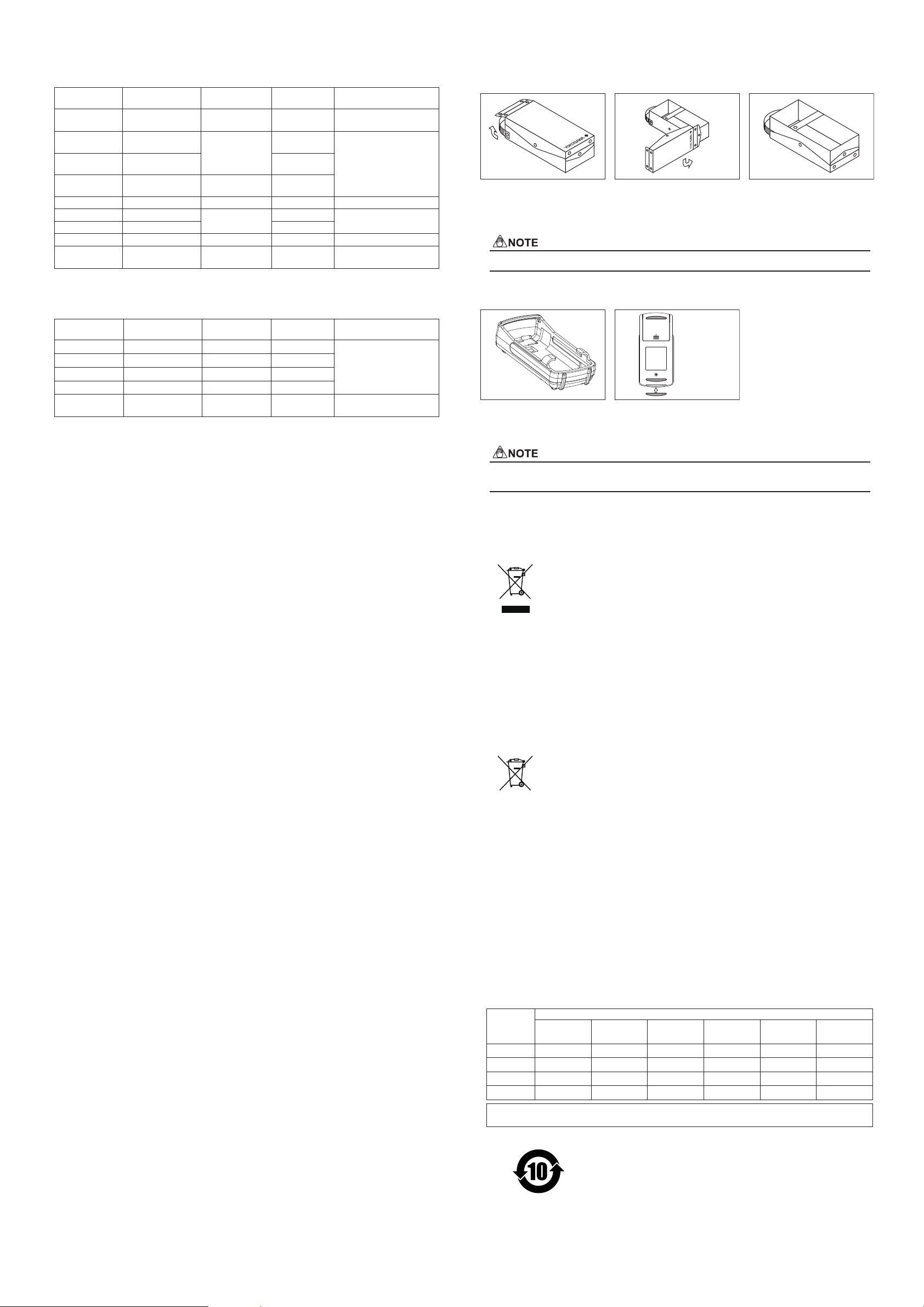
■ Carrying case (B9108NK)
The carrying case (B9108NK) may be used as follows:
(1) Undo the fasteners on the
top and sides of the case
cover to open it.
(2) With the fastener on the
logo-side of the case centered,
lift the cover and pivot it to the
side and under the case itself.
(3) Re-do the fasteners at the
top and sides of the cover
The fastener on the logo-side cannot be undone.
■ Rubber Boot (93038) ■ Anti-skid pad
Anti-skid pad
(supplied)
The optional rubber boot provides
shock protection and can be used
with a strap.
When using the instrument with a rubber boot, the anti-skid pad at the bottom is not needed.
When used without a rubber boot in a leaning position, the supplied anti-skid pad should be used.
11. Sales in Each Country or Region
11.1 Disposing the Product
Waste Electrical and Electronic Equipment (WEEE), DIRECTIVE 2012/19/EU
(This directive is valid only in the EU.)
This Product complies with the WEEE Directive (2012/19/EU) marking requirement.
This marking indicates that you must not discard this electrical/electronic product
in domestic household waste.
Product Category
With reference to the equipment types in the WEEE directive Annex I,
this product is classied as a “Monitoring and Control instrumentation” product.
When disposing products in the EU, contact your local Yokogawa Europe B. V. ofce.
Do not dispose in domestic household waste.
11.2 How to Replace and Dispose the Batteries
New EU battery Directive, DIRECTIVE 2006/66/EC
(This directive is valid only in the EU.)
Batteries are included in this product.
When you remove batteries from this product and dispose them, discard them in
accordance with domestic law concerning disposal.
Take a right action on waste batteries, because the collection system in the EU on
waste batteries are regulated.
Battery type: Alkaline dry cell
Notice:
The marking indicates they shall be sorted out and collected as
ordained in ANNEX II in DIRECTIVE 2006/66/EC.
How to remove batteries safely:
For more information, see Section 3. “Replacing Batteries” in
User's Manual - 1 - (IM CA11E-01E).
11.3 Authorized Representative in the EEA
Yokogawa Europe BV. shall act as Authorized Representative of Yokogawa Meters &
Instruments Corporation in the EEA for this Product.
To contact Yokogawa Europe BV., see the separate list of worldwide contacts,
PIM 113-01Z2. (EEA: European Economic Area)
11.4 For the Pollution Control of Electronic and Electrical Products of
the People's Republic of China
They are applicable only in the People's Republic of China.
产品中有毒有害物质或元素的名称及含量
部件名称
有毒有害物质或元素
铅
(Pb)
汞
(Hg)
镉
(Cd)
六价铬
(Cr(VI))
多溴联苯
(PBB)
多溴二苯醚
(PBDE)
框架(塑料) ××××○ ○
线路板 ASSY ××××○ ○
导线 ××××○ ○
电池 ××××○ ○
○:
×:
表示该部件的所有均质材料中的有毒有害物质的含量均在 GB/T 26572 标准中所规定的限量以下。
表示该部件中至少有一种均质材料中的有毒有害物质或元素的含量超过 GB/T 26572 标准所规定的限量要求。
环保使用期限 : 该标识适用于 SJ/T11364 中所述,在中华人民共和国销售的电子电气产品
的环保使用期限。
只要您遵守该产品相关的安全及使用注意事项,在自制造日起算的年限内,
则不会因产品中有害物质泄漏或突发变异,而造成对环境的污染或对人体
及财产产生恶劣影响。
注)
该年数为“环保使用期限”,并非产品的质量保证期。零件更换的推荐周期,
请参照使用说明书。
9. Specications
■ Source Functions
Accuracy: ±(% of set value+μV, mV or μA), at 23±5°C
Range
Selection Renge of
Generated Signal Accuracy Setting
Resolution Rmarks
30 V 0 to 30.00 V 0.05%+20 mV 10 mV Maximum output current:
1 mA
10 V 0 to 11.000 V 0.05%+2 mV 1 mV Maximum output current:
10 mA
*2: When the load is 1 kΩ
or greater, and the error of
the lead cables is also
exculuded.
1-5 V 1/2/3/4/5 V 1 V step
1 V 0 to 1100.0 mV 0.05%+0.2 mV *2 0.1 mV
100 mV 0 to 110.00 mV 0.05%+50 μV 10 μV ---
20 mA *1 0 to 24.000 mA 0.05%+4 μA 1 μA Maximum load: 12 V
4-20 mA *1 4/8/12/16/20 mA 4 mA step
24 V (20 mA) *1 24 V ±10% --- Maximum current: 22 mA
20 mA SINK *1 0.1 to 24.000 mA 0.1%+4 μA 1 μA External power supply:
5 to 28 V
Temperature coefcient: 1/10 of accuracy/°C, but (0.005% + 10 μV)/°C in the 100 mV range.
*1: The resolution can be changed between 5 digits and 4 digits using a DIP switch.
■ Measurement Functions
Accuracy: ±(% of reading+least signicant digits), at 23±5°C
Range
Selection Indication Accuracy Resolution Rmarks
30 V 0 to ±30.00 V 0.05%+2 dgt 10 mV
Input impedance:
Approx. 1 MΩ
10 V 0 to ±11.000 V 0.05%+2 dgt 1 mV
1 V 0 to ±1100.0 mV 0.05%+2 dgt 0.1 mV
100 mV 0 to ±110.00 mV 0.05%+7 dgt 10 μV
20 mA *1 0 to ±24.000 mA 0.05%+4 dgt 1 μV Input impedance:
45Ω
Temperature coefcient: 1/10 of accuracy/°C, but (0.005% + 10 μV)/°C in the 100 mV range.
*1: The resolution can be changed between 5 digits and 4 digits using a DIP switch.
■ General Specications
Power supply: Four 1.5-V alkaline batteries (LR6, AA-size) or
dedicated AC adapter (sold separately)
Battery life: Approximately 50 hours for 5 V DC output with a load of 10 kΩ or greater
(when running on alkaline batteries)
Approximately 25 hours for 20 mA output with a load of 5 V
(when running on alkaline batteries)
Automatic Power Off: After a period of approximately 10 minutes with no operations
Generation Signal Level Setting:
By four sets of up and down keys
Response of generator:
Approximately 1 second (between the time for an output signal to
start changing and the time when it enters the accuracy range)
Loading conditions: Less than 0.1 μF (DC V)
Measured-value indication updating intervals:
Approximately 1 second
Display: 7 segments LCD
Maximum allowable applied voltage:
30 V DC between each terminal and ground
Operating temperature and humidity range:
0 to 50°C, 20 to 80% RH (no condensation)
Storage temperature and humidity range:
-20 to 50°C, 90% RH or less (no condensation)
Dimension: Approximately 192 (H) × 92 (W) × 42 (D) mm (excluding protrusions)
Weight: Approximately 440 g (including batteries)
Accessories: Lead cables (B9108MS) for measurement and generation
(one pair, consisting of one black cable and one red cable)
Alkaline batteries - - - 4 pieces
User’s manuals - - - 3 copies
Optional accessories: DedicatedAC adapter
94012: AC100 V, 94013:AC120 V,
94016: AC 220-240 V (94016-F: VDE standard, 94016-S: BS standard)
Lead cables (B9108MS) for measurement and generation
(one set, consisting of one black cable and one red cable)
Carrying case (B9108NK)
Rubber boot (93038)
Strap (97040)
Accessory case (B9108XA)
Safety standards: EN61010-1, EN61010-2-030
(only AC adapter 94016, 94012 and 94013 are excluded.)
Measurement category O (other)
Indoor use, Altitude 2000 m or less, Pollution degree 2
EMC standards: EN61326-1 ClassB,
EN61000-3-2, EN61000-3-3
EMC Regulatory Arrangement in Australia and New Zealand
EN55011 Class B, Group 1
Korea Electromagnetic Conformity Standard
(한국 전자파적합성기준)
Measurement error may temporarily occur under immunity environments.
Test conditions of EMC and Immunity standards:
AC adapter (94016) and Lead cables (B9108MS) are used.

Other YOKOGAWA Test Equipment manuals

YOKOGAWA AQ1301 User manual

YOKOGAWA

YOKOGAWA AQ1301 User manual

YOKOGAWA ScopeCorder DL950 User manual

YOKOGAWA

YOKOGAWA ScopeCorder DL950 User manual

YOKOGAWA CA320 User manual

YOKOGAWA

YOKOGAWA CA320 User manual

YOKOGAWA 701928 User manual

YOKOGAWA

YOKOGAWA 701928 User manual

YOKOGAWA DL7200 User manual

YOKOGAWA

YOKOGAWA DL7200 User manual

YOKOGAWA DLM2000 Series User manual

YOKOGAWA

YOKOGAWA DLM2000 Series User manual

YOKOGAWA DL7440 User manual

YOKOGAWA

YOKOGAWA DL7440 User manual

YOKOGAWA AQ1215A User manual

YOKOGAWA

YOKOGAWA AQ1215A User manual

YOKOGAWA CA150 User manual

YOKOGAWA

YOKOGAWA CA150 User manual

YOKOGAWA MY40 User manual

YOKOGAWA

YOKOGAWA MY40 User manual

YOKOGAWA DL9040 Series User manual

YOKOGAWA

YOKOGAWA DL9040 Series User manual

YOKOGAWA CL255 User manual

YOKOGAWA

YOKOGAWA CL255 User manual

YOKOGAWA DL7440 User manual

YOKOGAWA

YOKOGAWA DL7440 User manual

YOKOGAWA CA71 HANDY CAL User manual

YOKOGAWA

YOKOGAWA CA71 HANDY CAL User manual

YOKOGAWA SL1000 User manual

YOKOGAWA

YOKOGAWA SL1000 User manual

YOKOGAWA CA320 User manual

YOKOGAWA

YOKOGAWA CA320 User manual

YOKOGAWA DLM2000 Series User manual

YOKOGAWA

YOKOGAWA DLM2000 Series User manual

YOKOGAWA 30032A User manual

YOKOGAWA

YOKOGAWA 30032A User manual

YOKOGAWA DLM3022 User manual

YOKOGAWA

YOKOGAWA DLM3022 User manual

YOKOGAWA HANDY CAL CA51 User manual

YOKOGAWA

YOKOGAWA HANDY CAL CA51 User manual

YOKOGAWA SL1400 ScopeCorder LITE User manual

YOKOGAWA

YOKOGAWA SL1400 ScopeCorder LITE User manual

YOKOGAWA DLM2000 Series User manual

YOKOGAWA

YOKOGAWA DLM2000 Series User manual

YOKOGAWA CA330 User manual

YOKOGAWA

YOKOGAWA CA330 User manual

YOKOGAWA DL1720E User manual

YOKOGAWA

YOKOGAWA DL1720E User manual

Popular Test Equipment manuals by other brands

AMB MYLAPS instruction manual

AMB

AMB MYLAPS instruction manual

Kikusui TOS8040 Operation manual

Kikusui

Kikusui TOS8040 Operation manual

SMART System 2000 instruction manual

SMART

SMART System 2000 instruction manual

Kemot MIE2125 owner's manual

Kemot

Kemot MIE2125 owner's manual

Tru-Test 702 user manual

Tru-Test

Tru-Test 702 user manual

VOLTCRAFT VC64 operating instructions

VOLTCRAFT

VOLTCRAFT VC64 operating instructions

Gammex Doppler 403 Flow Phantom manual

Gammex

Gammex Doppler 403 Flow Phantom manual

Sure Torque ST-LAB Operation and maintenance manual

Sure Torque

Sure Torque ST-LAB Operation and maintenance manual

Rothenberger ROCAM 4 Plus Instructions for use

Rothenberger

Rothenberger ROCAM 4 Plus Instructions for use

HOPETECH HT9980A user manual

HOPETECH

HOPETECH HT9980A user manual

Tektronix Keithley S500 Administrative guide

Tektronix

Tektronix Keithley S500 Administrative guide

Leagend T86 user manual

Leagend

Leagend T86 user manual

TIC TR-220 Operation manual

TIC

TIC TR-220 Operation manual

AEMC instruments CA7028 user manual

AEMC instruments

AEMC instruments CA7028 user manual

Seeed DSO203 user manual

Seeed

Seeed DSO203 user manual

Masibus PCE-MCA 50 user manual

Masibus

Masibus PCE-MCA 50 user manual

ACS Alert J5 quick guide

ACS

ACS Alert J5 quick guide

Martel MC1000 manual

Martel

Martel MC1000 manual

manuals.online logo
manuals.online logoBrands
  • About & Mission
  • Contact us
  • Privacy Policy
  • Terms and Conditions

Copyright 2025 Manuals.Online. All Rights Reserved.