Anlenne:
a) Der Einbau der Antenne erfolgt in den linken hinteren
Kotfliigel. Fig. 1 a SL Typen / Fig. 1b SLC Typen
b) Bohrung (24 mm @) anzeichnen und erstellen. Zum
Schutz des Lacks vorher rhit Klebeband abkleben. Aus-
kleidung des Kofferraums um die Bohrung herum aus-
schneiden.
c) Unterer Befestigungswinkel an der Antenne anschrauben.
d) Sechskantmutter von der Antenne abnehmen. Auf der
Antenne verbleiben das Zwischenst0ck und der Fettring.
Der Fettring dient als Korosionsschutz der Karosserie-
bohrung und bewirkt eine gute Masseverbindung der
Antenne mit der Karosserie.
e) Die Antenne vom Kofferraum aus in die Kotfltigelboh-
rung einsetzen. Dichtunterlage und PaBstuck (im Plastik-
beutel verpackt der Antenne beiliegend) und Sechs-
kantmutter auf die Antenne stecken und leicht anziehen.
t) Mit dem Haltewinkel die Antenne an dem vorhandenen
Befestigungsbiigel anschrauben. Die Antenne ausrichten,
Sechskantmutter am Antennenkopf fest anziehen, dann
erst dle Blechschraube am Haltewinkel anziehen.
g) Das im Wagen bereits serienmABig verlegte Antennen-
kabel lindet sich nahe der Kotfliigelbohrung angeklam-
mert. Den KabelanschluB an der Antenne {est anschrau-
ben.
h) Das elektrische AnschluBkabel von der Antenne unter
der Koflerraumauskleidung zur linken Rtickleuchte ver-
legen. Nach Abnahme der Leuchtenriickwand erfolgt der
AnschluB an vorhandener Steckkupplung ,,K" und sepa-
rater Masseschraube ,,M", an der die schwarze Ader
befestigt wird (Fig. 1 d).
Die beim Einbauraum eingebundene Steuerleitung ist
am Empfdnger anzuschlieBen.
Anmerkung:
Bei Wagen, die nictrt serienmdBig filr den Einbau der Voll-
automatic-Antenne Auta 6000 H 461 ausgerUstet sind, muB
bei folgenden Arbeitsabschnitten abweichend beachtet
werden:
Das fehlende Antennenkabel nachtrdglich verlegen (Fig. 1 e)
Antennenkabel mit SchraubanschluB 4,5 m lang
H irschmann Ersatztei I Bestell-Nr. 825 720-OO1
Bei diesen Wagen befindet sich die Steckkupplung fur den
elektrischen AnschluB der Antenne vorn links am Feststell-
bremstrdger. Die Motorleitung an der Antenne ca. 20 cm
vom Stecker abschneiden. Die 3 Adern (rot-weiB-schwarz)
abisolieren und mit entsprechender Leitung (mindestens
3x1,594m lang) und Kabelverbindern verldngern. Frir den
AnschluB an, der vorhandenen Steckkupplung den passen-
den 4fach-Stecker anlciten, wobei die einzelnen Leitungen
- bezogen auf die AnschluBleitung der Antenne - an fol-
gende Steckerstift-Nummer angelotet werden m0ssen:
Steckerstift-Nr. 1 - roteAder
Steckerstift-Nr. 2 - schwarze Ader
Steckerstift-Nr. 3 - weiBe Ader
Steckerstift-Nr. 4 - bleibt frei.
Den Stecker bitte bei Daimler-Benz als Ersatzteil besorgen.
Kostal-Stecker Nr. 099604 10
Daimler-Benz Nr. 005 5451428KZ.
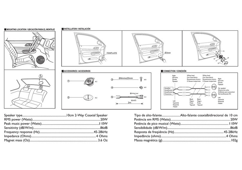
Die Verleguno der beiden Kabel erfolgt auf der linken Seite
entlang dem vorhandenen Kabelbaum. Dazu Sitzkissen und
Rtickenlehne entfernen, Seitenverkleidung l6sen und Ab-
deckleiste auf der Ttirschwelle abschrauben.
Fig. 1
Antenneneinbau
lnstallation of antenna
Antenna:
a) The antenna installation is carried out in the rear left-
hand mudguard. Fig. 1 a SL Types / fig. 1 b SLC Types
b) Pre-mark and then eflect boring (24 mm @). Cover with
masking tape before starting in order to protect the
lacquer. Cut out the lining of the luggage compartment
in the area around the boring.
c) Screw the underneath fastening angle onto the antenna
(fig. 1 c).
d) Remove the hexagonal nut from the antenna. The con-
nection piece and fat ring remain on the antenna. The
fat ring serves as rust protection for the car body boring
and effects a good earth connection between the an-
tenna and the car body.
e) lnsert the antenna into the nudguard boring via the
luggage compartment. Plug t re sealer and fitting piece
(located in the plastic bag packed to the antenna), as
well as the hexagonal nut onto the antenna and tighten
lightly.
f) Screw the antenna onto the already present fastening
support with the aid of the holding angle. Extend the
antenna, screw the hexagonal nut tightly onto the an-
tenna head, and then tighten the self-tapping screw on
the supporting angle.
g) The antenna cable which is serially built into all cars is
attached to the car in the area of the mudguard boring.
Screw the cable connection tightly onto the antenna.
h) Lay the electrical connection cable from the antenna
underneath the lining of the luggage compartment to
the rear left-hand light. Remove the light covering and
then effect the connection to the already present plug
connection ,,K" and to the separate earth screw ,,M",
to which the black wire is fastened (fig. 1 d). The band
pilot wire located in the installation area iS to be con-
nected to the receiver.
Note:
Please take note of the followinq altered instructions in the
case of cars which are not serially equipped for the in-
stallation of the fully automatic antenna Auta 6000 H 461 :
Lay the missing antenna cable subsequently (lig. 1 e).
Antenna cable with screw connection 4,5 m long.
Hirschmann spare part, Order No. 825720-001.
ln the case of these cars, the plug contact for the electrical
connection of the antenna is located on the tront left-hand
side of the manually operated brake holder. Cut ofl the an-
tenna motor cable at a distance ol approximately 20 cm
from the plug.
lnsulate the three wires (red/white/black) and extend with
the relative cable (minimum 3x1,59 4m long) and cable
leads. For the connection onto the already present plug
connection, solder on the corresponding four-point plug,
whereby the individual leads - referring to the connection
cable of the antenna - must be soldered to the following
plug pin numbers: ,
Plug pin No. 1 - red wire
Plug pin No. 2 - black wire
Plug pin No. 3 - white wire
Plug pin No. 4 - remains vacant
Please obtain the plug as a spare part from Daimler-Benz.
Kostal plug No. 099 604 10
Daimler-Benz No. 005 545 1428Kz.
The laying of both plugs is carried out on the left-hand side
along the already present cable tree. Remove'the seat
cushions and the back rest, loosen the side covering and
unscrew the finishing strip on the door sill in order to
carry out this procedure.
Fig. 1-b
Fig. 1 a

