manuals.online logo
Brands
  1. Home
  2. •
  3. Brands
  4. •
  5. BEGA
  6. •
  7. Accessories
  8. •
  9. BEGA 70 635 User manual

BEGA 70 635 User manual

BEGA Gantenbrink-Leuchten KG · Postfach 31 60 · 58689 Menden · info@bega.com · www.bega.com
34.18 · Technische Änderungen vorbehalten · Technical amendments reserved · Modications techniques réservées
IP 54
!
Anschlusskasten
Connection box
Boîte de connexion
70 635
7575 8585
275275
290290
Gebrauchsanweisung Instructions for use Fiche d’utilisation
Anwendung
Kabelanschlusskasten mit Leistungs-
reduzierung für BEGA LED-Aufsatzleuchten
mit 1-10 V Schnittstelle für den Einbau in
Lichtmaste.
Die Leistungsreduzierung basiert auf der
positiven Schaltlogik, d.h. die Reduzierung
erfolgt bei abgeschalteter Steuerphase.
Application
Cable connection box with power reduction
for BEGA LED pole top luminaires with 1-10 V
interface for installation in poles.
The power reduction is based on a positive
switch logic, i.e. reduction at switched-off
control phase.
Utilisation
Boîte de connexion avec réduction de
puissance pour luminaires BEGA
à LED avec interface 1-10 V pour l'installation
dans des mâts.
La réduction de puissance repose sur la
logique de commutation positive c'est à dire
que la réduction s'opère quand la ligne pilote
est coupée.
Produktbeschreibung
Anschlusskasten gemäß
DIN 43 628/ VDE 0660 · Teil 505
Gehäuse besteht aus schlagzähem
Kunststoff, Polycarbonat
Brandschutz nach VDE 0304 Teil 3,
schwer entammbar und selbstverlöschend
Gehäusedeckel klar mit Schraubbefestigung
2 Befestigungslanglöcher ø 7 mm
Abstand 275 mm
für den Einbau in Maste ø > 120 mm
Türgröße ab 80 x 300 mm
2 Kabeleinführungen mit zweiteiliger
Kunststoffdichtung und integrierter
Zugentlastung für Erdkabel 5 x 16@
2 Leitungseinführungen mit Dichtnippel für
Leuchtenanschlussleitung 5 x 2,5@
1 zusätzliche Anschlussklemme 2,5@
für den Anschluss der Steuerphase LST
2 Sicherungshalter mit Schraubkappe
für Schmelzsicherung Neozed D01 bis 16A
mit eingesetzter Sicherung Neozed D01· 6A
Leistungsumschalter mit positiver Logik
Steuerphase ein: 100 % Leistung
Steuerphase aus: 50 % Leistung
Steuerspannung 220-240 V · 50/60 Hz
Schutzart IP 54
Staubgeschützt und Schutz gegen
Spritzwasser
c – Konformitätszeichen
Gewicht: 0,85 kg
Product description
Connection box according to
DIN 43 628/ VDE 0660 · Part 505
Housing made of impact synthetic plastic,
polycarbonate
Fire protection according to VDE 0304 Part 3,
ame resistant and self-extinguishing
Clear housing cover with screw mounting
2 elongated xing holes ø 7 mm
Spacing 275 mm
for installation in poles ø > 120 mm
Door size from 80 x 300 mm
2 cable entries with two-part plastic gasket
and integrated strain-relief for underground
cable 5 x 16@
2 cable entries with compression nipples for
luminaire connecting cable 5 x 2,5@
1 additional connecting terminal 2,5@
for connection of control phase LST
2 fuse holders with screw cap for fuse Neozed
D01 up to 16 A
equipped with fuse Noezed D01· 6 A
Power changeover switch - positive logic -
Control phase on:100 % power
Control phase off: 50 % power
Control voltage 220-240 V · 50/60 Hz
Protection class IP 54
Protection against harmful dust deposits and
splash water
c – Conformity mark
Weight: 0.85 kg
Description du produit
Boîte de connexion selon
DIN 43 628/ VDE 0660 - Partie 505
Boîtier fabriqué en matière plastique, résistant
aux chocs, polycarbonate
Protection contre le feu selon VDE 0304
partie 3, difcilement inammable et
auto-extinguible
Couvercle du boîtier transparent vissé
2 trous de xation diamètre ø 7 mm
Entraxe 275 mm
pour l'installation dans les mâts ø > 120 mm
Dimensions de la porte 80 x 300 mm
2 entrées de câble avec joint en plastique en
deux parties et collier anti-traction intégré pour
câble réseau 5 x 16@
2 entrées de câble de raccordement avec
nipple d'étanchéité pour câble du luminaire
5 x 2,5@
1 bornier supplémentaire 2,5 @pour
raccordement de la ligne pilote LST
2 porte fusibles avec bouchon leté pour fusible
Neozed D01 jusqu'à 16 A avec fusible intégré
Neozed D01· 6A
Commutateur de puissance en logique positive
Ligne pilote en service: Puissance 100 %
Ligne pilote coupée: Puissance 50 %
Tension de commande 220-240 V · 50/60 Hz
Degré de protection IP 54
Protection contre la poussière et les projections
d’eau
c – Sigle de conformité
Poids: 0,85 kg
Sicherheit
Für die Installation und für den Betrieb
dieses Ergänzungsteils sind die nationalen
Sicherheitsvorschriften zu beachten.
Der Hersteller übernimmt keine Haftung für
Schäden, die durch unsachgemäßen Einsatz
oder Montage entstehen.
Werden nachträglich Änderungen an dem
Ergänzungsteil vorgenommen, so gilt derjenige
als Hersteller, der diese Änderungen vornimmt.
Safety
The installation and operation of this accessory
are subject to national safety regulations.
The manufacturer is then discharged from
liability when damage is caused by improper
use or installation.
If any accessory is subsequently modied, the
persons responsible for the modication shall
be considered as manufacturer.
Sécurité
Pour l’installation et l’utilisation de cet
accessoire, respecter les normes de sécurité
nationales.
Le fabricant décline toute responsabilité
résultant d’une mise en œuvre ou d’une
installation inappropriée du produit.
Toutes les modications apportées à cet
accessoire se feront sous la responsabilité
exclusive de celui qui les effectuera.
BEGA Gantenbrink-Leuchten KG · Postfach 31 60 · 58689 Menden · info@bega.com · www.bega.com
Montage
Schraube lösen und Gehäusedeckel
abnehmen. Befestigungsschrauben der
Kabelschelle lösen und Schellenoberteil mit
Dichtungseinsatz herausnehmen.
Schellenober- und Schellenunterteil
entsprechend der Anzahl und des
Durchmessers der Zugangskabel anpassen.
Zugangskabel abisolieren und so einlegen,
dass der Außenmantel mindestens 5 mm in
den Anschlusskasten hineinragt.
Bitte beachten Sie:
Bei nur einem Zugangskabel ist dieses immer
links einzuführen. Kabelschelle montieren.
Schutzleiterverbindung herstellen und
elektrischen Anschluss an Klemme L1, N
und PE vornehmen. Der Anschluss der
Steuerleitung erfolgt an der losen Klemme LST.
Leuchtenanschlussleitungen durch die oberen
Dichtnippel in den Anschlusskasten einführen.
Der Netzanschluss der LED-Leuchte erfolgt
über die braune, blaue und grün-gelbe Ader an
den Klemmen L · N · PE.
Die beiden mit 1-10 V +und 1-10 V -
gekennzeichneten Adern sind an der Klemme
1-10 V aufzulegen.
Die Ansteuerung der 1-10 V Schnittstelle
erfolgt über eine Beschaltung mittels
der im Anschlusskasten eingebauten
Widerstandskaskade.
Der erforderliche Widerstandswert ist in der
Gebrauchsanweisung der eingesetzten
LED-Leuchte unter dem Abschnitt
"Leistungsreduzierung" aufgeführt oder
kann unter Angabe von Artikelnummer und
Fertigungscode der Leuchte bei BEGA
angefragt werden.
Installation
Undo screw and remove housing cover.
Undo xing screws of the cable clamp and
take out upper part of cable clamp with gasket
insert.
Adapt upper and lower part of the cable clamp
according to the number and diameter of the
mains supply cables.
Strip mains supply cable and insert it in such
a way that the cable sheathing is led at least
5 mm into the connection box.
Please note:
In case of only one mains supply insert it
through the left sided opening of the cable
clamp. Assemble cable clamp.
Make earth conductor connection and make
electrical connection at terminal L1, N and PE.
The connection of the control line has to be
carried out at the loose connection LST.
Lead the luminaire connecting cables through
the compression nipples into the connection
box.
The mains supply connection of the LED
luminaire has to be made to the brown, blue
and green-yellow core at terminals L · N · PE.
The cables marked with 1-10 V +and 1-10 V -
are to be connected at terminal 1-10 V.
The control of the 1-10 V interface is done
by means of wiring of the resistor cascade
installed in the connection box.
The required resistance value is listed under the
heading “Power reduction” in the instructions
for use for the corresponding LED luminaire;
alternatively, it may be obtained from BEGA
on request by quoting the article number and
production code of the luminaire.
Installation
Desserrer la vis et ôter le couvercle.
Desserrer les vis de xation du collier de câble
et retirer la partie supérieure du collier avec le
joint.
Ajuster la partie supérieure et la partie inférieure
du collier en fonction du nombre et du diamètre
des câbles d'alimentation.
Dénuder le câble d'alimentation et insérer le
de façon que la gaine extérieure pénètre d'au
moins 5 mm dans la boîte de connexion.
Attention :
Quand un seul câble de raccordement est
utilisé, il doit être inséré à gauche.
Installer le collier du câble.
Mettre à la terre et procéder au raccordement
électrique au bornier L1, N et PE.
Le raccordement de la ligne pilote est effectué
au bornier non xé LST.
Introduire les câbles des luminaires dans
la boîte de connexion à travers les nipples
d'étanchéité supérieures.
Le raccordement électrique du luminaire à LED
est effectué par le l marron, bleu et vert-jaune
aux bornes L · N · PE.
Les deux ls marqués par 1-10 V +et 1-10 V -
doivent être branchés au bornier 1-10 V.
Le pilotage de l’'interface 1-10 V doit être
réalisé via un circuit externe de la sortie de
l’unité de commutation par l’intermédiaire d’une
résistance appropriée.
La valeur de résistance requise est indiquée
dans la che d’utilisation du luminaire à LED à
la rubrique « Réduction de puissance » et peut
être obtenue sur demande auprès de BEGA
en indiquant le numéro d’article et le code de
fabrication du luminaire.
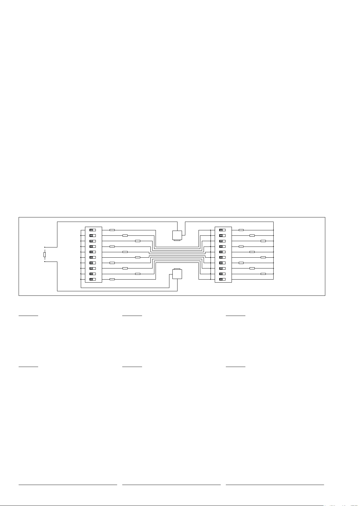
Switch 1
ON
1 3456789102
Switch 2
9 kΩ
8 kΩ
7 kΩ
6 kΩ
5 kΩ
4 kΩ
3 kΩ
2 kΩ
1 kΩ
0,33 kΩ
80 kΩ
70 kΩ
0,66 kΩ
60 kΩ
50 kΩ
40 kΩ
30 kΩ
20 kΩ
10kΩ
IN
Resistor
OUT
ON
1 3456789102
Beispiel:
Widerstandwert 51 kΩ
Switch 1: DIP-Schalter 1 auf "ON"
Switch 2: DIP-Schalter 5 auf "ON"
Bei Widerstandswerten kleiner 1 kΩmuss
an Switch 2 der Dipschalter 9 oder 10 und
an Switch 1 der Dipschalter 10 (Durchgang)
betätigt werden.
Beispiel:
Widerstandwert 0,66 kΩ
Switch 1: DIP-Schalter 10 auf "ON"
Switch 2: DIP-Schalter 10 auf "ON"
Example:
Resistance value for luminaire 51kΩ
Switch 1: DIP switch 1 to "ON"
Switch 2: DIP switch 5 to "ON"
For resistance values less 1kΩat Switch 2 DIP
switch 9 or 10 and at Switch 1 DIP switch 10
(through-wiring) must be activated.
Example:
Resistance value for luminaire 0,66 kΩ
Switch 1: DIP switch 10 to "ON"
Switch 2: DIP switch 10 to "ON"
Exemple:
Valeur de résistance 51 kΩ
Switch 1:DIP switch 1 sur "ON"
Switch 2: DIP switch 5 sur "ON"
Pour des valeurs de résistance de moins de
1kΩon doit activer sur Switch 2, l'interrupteur
DIP 9 ou 10 et sur Switch 1, l'interrupteur DIP
10 (passage).
Exemple:
Valeur de résistance 0,66 kΩ
Switch 1: DIP switch 10 sur "ON"
Switch 2: DIP switch 10 sur "ON"
Ersatzteile
Leistungsumschalter 61000838
Spares
Power change-over switch 61000838
Pièces de rechange
Régulateur de tension 61000838

Other BEGA Accessories manuals

BEGA 13 567 User manual

BEGA

BEGA 13 567 User manual

BEGA 71 096 User manual

BEGA

BEGA 71 096 User manual

BEGA 71 100 User manual

BEGA

BEGA 71 100 User manual

BEGA 10 713 User manual

BEGA

BEGA 10 713 User manual

BEGA 71190 User manual

BEGA

BEGA 71190 User manual

BEGA 71 190 User manual

BEGA

BEGA 71 190 User manual

BEGA 70 821 User manual

BEGA

BEGA 70 821 User manual

Popular Accessories manuals by other brands

Endress+Hauser Oxymax COS61D operating instructions

Endress+Hauser

Endress+Hauser Oxymax COS61D operating instructions

Vooni Stone manual

Vooni

Vooni Stone manual

elsner elektronik WG AQS/TH gl quick start guide

elsner elektronik

elsner elektronik WG AQS/TH gl quick start guide

Satel S-4 quick start guide

Satel

Satel S-4 quick start guide

IFM Electronic efector 800 VSE100 operating instructions

IFM Electronic

IFM Electronic efector 800 VSE100 operating instructions

Hytronik HMW21 Installation and instruction manual

Hytronik

Hytronik HMW21 Installation and instruction manual

Orbis DICROMAT quick start guide

Orbis

Orbis DICROMAT quick start guide

SunSetter EASYSHADE Replacement

SunSetter

SunSetter EASYSHADE Replacement

Manitowoc 7626473 Installation & adjustment instructions

Manitowoc

Manitowoc 7626473 Installation & adjustment instructions

D+H WRS-S Original instructions

D+H

D+H WRS-S Original instructions

Campbell Wintersense SDI-12 product manual

Campbell

Campbell Wintersense SDI-12 product manual

A&D AD4329A-DLC instruction manual

A&D

A&D AD4329A-DLC instruction manual

MOPEKA Pro Sensor quick start guide

MOPEKA

MOPEKA Pro Sensor quick start guide

Baumer UNAR 18N7903/S14G manual

Baumer

Baumer UNAR 18N7903/S14G manual

Emery Winslow 7600E Configuration and setup

Emery Winslow

Emery Winslow 7600E Configuration and setup

LuxaFlex Base Plus installation guide

LuxaFlex

LuxaFlex Base Plus installation guide

Rinstrum R323 Communications manual

Rinstrum

Rinstrum R323 Communications manual

Manitowoc 7622073 Mounting instructions

Manitowoc

Manitowoc 7622073 Mounting instructions

manuals.online logo
manuals.online logoBrands
  • About & Mission
  • Contact us
  • Privacy Policy
  • Terms and Conditions

Copyright 2025 Manuals.Online. All Rights Reserved.