230Vac - 50Hz 216Vdc
VAW
31121 8,6 6,8
A ARECCHI ER SEGNALETICA
E ILLUMINAZIONE DI EMERGENZA
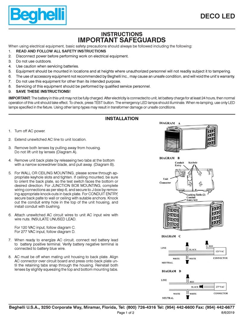
L’apparecchio consente di centralizzare l'accensione
e lo spegnimento integrando funzioni di diagnosi.
L’apparecchio è dotato di un selettore rotativo per
l’indirizzamento (Fig. E1).
In alternativa l’acquisizione in centrale può essere
effettuata automaticamente tramite il riconoscimen-
to dell’ID (Fig. E2).
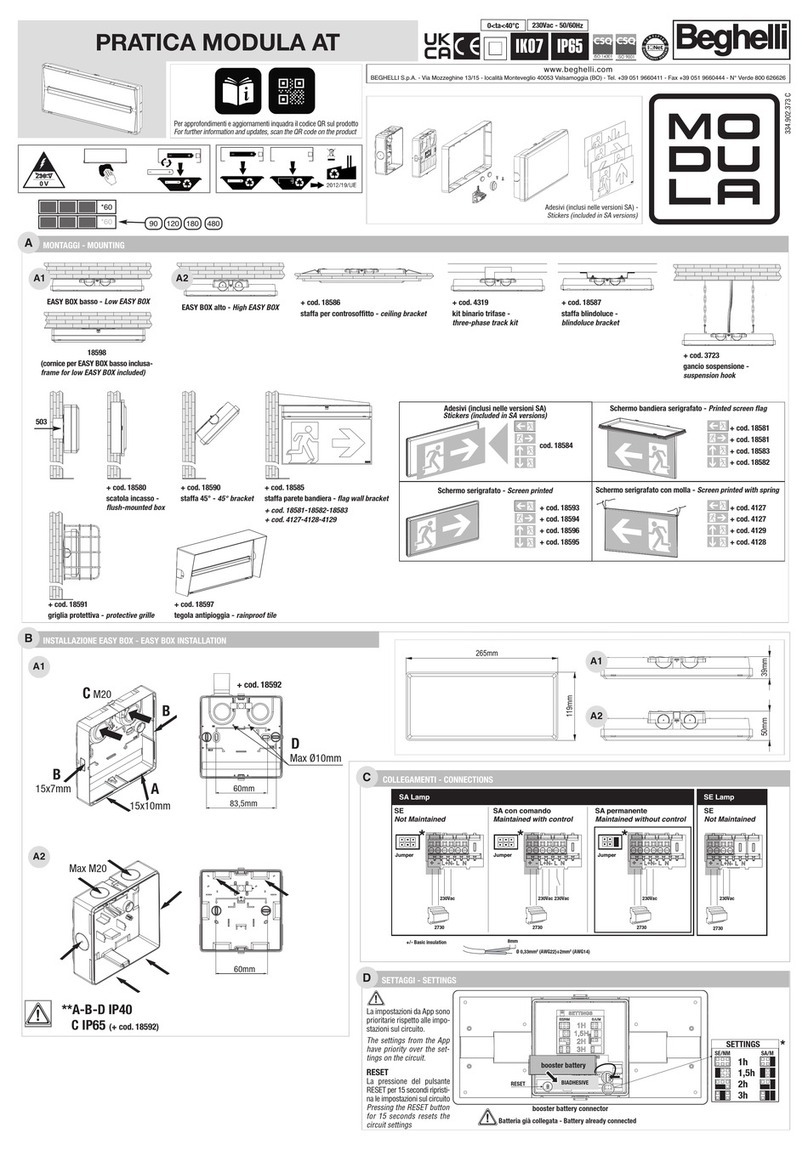
(Fig. D) SCHEMI DI COLLEGAMENTO
- Collegamenti rete (L/+ ; N/-) rispettare le polarità.
- Collegamenti controllo LSSA: L; N (tensione 198 V
a 254 V~) (Fig. D1-D2).
Il flusso luminoso in modalità emergenza è pari a
quello emesso in modo ordinario salvo diverso com-
portamento dell’alimentatore.
FUNZIONE COMANDO LOCALE LSSA:
(Fig. D1) Funzione di comando tramite interruttore,
posizionare il DIP Switch “LSSA” su “ON” e il DIP
Switch “UV” su “LS-T”: l'apparecchio si accende se
c’è tensione sull'ingresso locale.
(Fig. D2) Monitoraggio di mancanza rete locale, posi-
zionare il DIP Switch “LSSA” su “ON” e il DIP Switch
“UV” su “LS-F”: l'apparecchio si accende in EMER-
GENZA se NON c’è tensione sull'ingresso locale.
(Fig. D2) Funzione di comando tramite interruttore,
posizionare il DIP Switch “LSSA” su “ON” e il DIP
Switch “UV” su “LS-F” - l’apparecchio si accende in
modalità ordinaria, se non c’è tensione sull'ingresso
locale. Per attivare questa funzione consultare il
manuale d’uso in dotazione con la Centrale.
L'apparecchio deve essere comunque programmato
in modo NON PERMANENTE sulla Centrale.
FUNZIONE SENZA COMANDO LOCALE LSSA:
(Fig. D3) Posizionare il DIP Switch su OFF; lo stato del-
l'apparecchio è determinato dalla programmazione
effettuata sulla Centrale (Permanente, Non
Permanente, Attivazione temporizzata, attivazione su
comando centralizzato).
ROGRAMMAZIONE SOGLIE DI DIAGNOSI
DIP switch settato di fabbrica.
Se la lampada è guasta, la corrente assorbita dal
reattore elettronico deve essere inferiore a “WFAIL”
(Fig. D).
CODIFICA
Indirizzi: da 1 a 16: (Fig. E1).
Indirizzi: da 17 a 32: (Fig. E1).
AVVERTENZE - GARANZIA
- Questo apparecchio dovrà essere destinato solo
all'uso per il quale è stato costruito. Ogni altro uso
è da considerarsi improprio e pericoloso.
- Per eventuali riparazioni rivolgersi ad un centro di
assistenza tecnica autorizzato e richiedere l'utiliz-
zo di ricambi originali. Il mancato rispetto di quan-
to sopra può compromettere la sicurezza dell'ap-
parecchio.
- Per le modalità di intervento in garanzia contatta-
re il Numero Verde 800 626626 o il Rivenditore
Autorizzato.
NOUZOVÁ SVÍTIDLA RO NOUZOVÉ ZNAČENÍ A
ÚNIKOVÉ CESTY
Svítidlo umožňuje centrální spínání i diagnostické
funkce. Svítidlo je vybaveno spínačem pro manuální
adresování (Obr. E1).
Případněmůže být adresování provedeno auto-
maticky přes centrální jednotku a to načtením ID
(Obr. E2).
(Obr. D) SCHÉMA ZA OJENÍ
- S ohledem na síťové připojení (L/+; N/-) a
polaritu.
-Připojení LSSA vstupu: L; N (napětí 198 V až 254
V ~) (Obr. D1-D2). Světelný tok při normálním a
nouzovém provozu je stejný, s výjimkou odchylky
ovládacího zařízení.
ROVOZ S MÍSTNÍM LSSA ŘÍKAZEM:
(Obr. D1) Pro funkci místního světelného spínače
přepněte přepínačDIP z "LSSA" na "ON" a přepínač
DIP z "UV" na "LS-T" – zařízení se zapne v
normálním režimu se současným napětím na
místním vstupu.
(Obr. D2) Pro funkci monitorování místní sub-distri-
buce přepněte přepínačDIP z "LSSA" na "ON" a
přepínačDIP z "UV" na "LS-F" – zařízení se zapne
v nouzovém režimu bez napětí na místním vstupu.
(Obr. D2) Pro funkci místního invertorového svě-
telného spínače přepněte přepínačDIP z "LSSA"
na "ON" a přepínačDIP z "UV" na "LS-F" – zařízení
se zapne v normálním režimu bez napětí, též v pří-
paděpřepětí nebo podpětí na místním vstupu.
Chcete-li aktivovat tuto funkci, přečtěte si návod k
obsluze centrální jednotky.
Zařízení musí být naprogramováno do režimu
Nouzového svícení prostřednictvím centrální
jednotky.
ROVOZ BEZ MÍSTNÍHO LSSA ŘÍKAZU:
(Obr. D3) Přepněte přepínačDIP do polohy "OFF".
Zařízení se přepne programováním na centrální jed-
notce.
KALIBRACE ŘI OJENÉHO ŘÍKONU
Tovární přepínačDIP.
Pokud je svítidlo vadné, spotřeba proudu předřadníku
musí být menší než "W FAIL" (Obr. D).
KÓDOVÁNÍ
Adresy: od 1 do 16 – (Obr. E1).
Adresy: od 17 do 32 – (Obr. E1).
U OZORNĚNÍ - ZÁRUKA
- Toto zařízení může být použito pouze k účelu, pro
nějž bylo vyrobeno. akékoliv jiné použití bude
považováno za nevhodné a tím také nebezpečné.
- Pro případné opravy se obraťte na autorizované
servisní středisko, které používá pouze originální
náhradní díly. Nerespektování výše uvedených
podmínek může ohrozit bezpečnost svítidla.
EMERGENCY LUMINAIRE
FOR EXIT SIGNS
AND ESCA E ROUTES
The luminaire allows a centralised switching as well
as diagnostic functions.
The luminaire is equipped with a rotary switch for
manual addressing (Fig. E1). Alternatively the addres-
sing can be done automatically over the central by
read-in of the ID (Fig. E2).
(Fig. D) WIRING DIAGRAM:
- Consider mains connections (L/+; N/-) and polarity.
- Connections of the LSSA input: L; N (voltage 198 V
to 254 V~) (Fig. D1-D2).
The light flux in normal operation and emergency
operation is the same, except of deviating perfor-
mance of the control gear.
O ERATION WITH LOCAL LSSA COMMAND:
(Fig. D1) For a function as local light switch, put DIP
switch “LSSA” to “ON” and DIP switch “UV” to “LS-
T” – the device will be switched on in normal opera-
tion with present voltage on the local input.
(Fig. D2) For a function as local sub-distribution moni-
toring, put DIP switch "LSSA" to "ON" and DIP swit-
ch "UV" to "LS-F" - the device will be switched on in
emergency operation with absent voltage on the local
input.
(Fig. D2) For a function as local inverted light switch,
put DIP switch "LSSA" to "ON" and DIP switch "UV"
to "LS-F" - the device will be switched on in normal
mode with absent voltage on the local input. To acti-
vate this function consult the operating manual of
the central.
The device must be programmed to non-maintained
mode over the central.
O ERATION WITHOUT LOCAL LSSA COMMAND:
(Fig. D3) Put DIP switch in position "OFF". The devi-
ce will be switched by the programming on the
central.
CALIBRATION OF THE CONNECTION LOAD:
Factory-set DIP switch.
If the illuminant is defective the current consumption
of the control gear must be smaller than “WFAIL”
(Fig. D).
CODING
Addresses: from 1 to 16: (Fig. E1).
Addresses: from 17 to 32: (Fig. E1).
WARNINGS - GUARANTEE
- This device shall be used exclusively for the purpose
for which it has been designed. Any other use is
considered improper and therefore dangerous.
- Contact an authorised technical service centre for
repairs possibly required use only original spare
parts. The lacked respect of the above conditions
may compromise the safety of the device.
- For details regarding warranty services, contact an
authorized dealer.
NOTLEUCHTE
FÜR RETTUNGSZEICHEN
UND FLUCHTWEGE
Die Leuchte ermöglicht ein zentralisiertes Schalten
sowie Diagnosefunktionen.
Die Leuchte ist mit einem Drehschalter zur manuel-
len Adressierung ausgestattet (Abb. E1).
Alternativ kann die Adressierung automatisch über die
Zentrale durch Einlesung der ID erfolgen (Abb. E2).
(Abb. D) ANSCHLUSSSCHEMA:
-Netzanschlüsse (L/+; N/-) und Polung berücksi-
chtigen.
-Anschlüsse des LSSA-Eingangs: L; N (Spannung
198 V bis 254V~) (Abb. D1-D2).
Der Lichtstrom ist im Normalbetrieb und Notbetrieb
gleich, außer bei abweichendem Verhalten des
Vorschaltgeräts.
BETRIEB MIT LOKALEM LSSA-BEFEHL:
(Abb. D1) Für eine Funktion als Lichtschalter DIP-
Schalter “LSSA” auf “ON” stellen und DIP-Schalter
“UV” auf “LS-T” stellen – das Gerät wird bei anlie-
gender Spannung am lokalen Eingang im
Normalbetrieb eingeschaltet.
(Abb. D2) Für eine Funktion als lokale
Unterverteilungsüberwachung, DIP-Schalter "LSSA"
auf "ON" stellen und DIP-Schalter "UV" auf "LS-F"
stellen - das Gerät wird bei fehlender Spannung am
lokalen Eingang im Notbetrieb eingeschaltet.
(Abb. D2) Für eine Funktion als lokaler, invertierter
Lichtschalter, DIP-Schalter "LSSA" auf "ON" stellen
und DIP-Schalter "UV" auf "LS-F" stellen - das Gerät
wird bei fehlender Spannung am lokalen Eingang im
Normalbetrieb eingeschaltet. Um diese Funktion zu
aktivieren, konsultieren Sie die Bedienungsanleitung
der Zentrale.
Das Gerät muss über die Zentrale auf
Bereitschaftsschaltung programmiert sein.
BETRIEB OHNE LOKALEN LSSA-BEFEHL:
(Abb. D3) DIP-Schalter auf Position "OFF" stellen.
Das Gerät wird durch die Programmierung an der
Zentrale geschaltet.
KALIBRIERUNG DER ANGESCHLOSSENEN LAST:
DIP-Schalter im Werk voreingestellt.
Wenn das Leuchtmittel defekt ist, muss die
Stromaufnahme des Vorschaltgeräts kleiner als
“WFAIL” sein (Abb. D).
KODIERUNG
Adressen: von 1 bis 16: (Abb. E1).
Adressen: von 17 bis 32: (Abb. E1).
WARNUNGEN - GARANTIE
- Das Gerät darf ausschließlich für den Zweck, für den
es hergestellt wurde, verwendet werden. ede davon
abweichende Verwendung wird als nicht zweckent-
sprechend und somit als gefährlich angesehen.
-Wenden Sie sich bei Reparaturen an eine autori-
sierte Servicestelle oder fordern Sie
Originalersatzteile an. Das Nichteinhalten vor-
stehender Bestimmungen kann die Gerätesicherheit
gefährden.
-Für die Vorgehensweise bei Garantieleistungen
wenden Sie sich an den autorisierten Händler.
E1E2
ADDRESS
16
32
1
17
2
18
3
19
4
20
5
21
6
22
7
23
8
24
9
25
10
26
11
27
12
28
13
29
14
30
15
31
1-16
17-32
16
32
1
17
2
18
3
19
4
20
5
21
6
22
7
23
8
24
9
25
10
26
11
27
12
28
13
29
14
30
15
31
16
32
1
17
2
18
3
19
4
20
5
21
6
22
7
23
8
24
9
25
10
26
11
27
12
28
13
29
14
30
15
31
456659
8
9
1
0
Luminairesaddress
1
F
OF
2
2
1
ON
8/N
7/L
