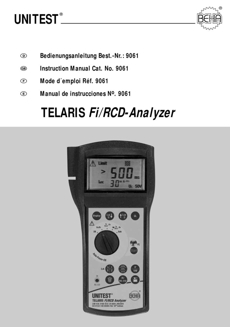
BEHA Unitest TELARIS 0100 plus User manual

1
UNITEST
Instruction Manual Cat.-No. 9073
®
TELARIS 0100 plus

2

Content ........................................................................................................Page
1.0 Introduction ..............................................................................................4
1.1 Model and Type ........................................................................................4
1.2 Product description ..................................................................................4
2.0 Transport and Storage ..............................................................................5
3.0 Safety Measures ......................................................................................5
3.1 Appropriate Usage ..................................................................................6
4.0 Display and Control Elements ..................................................................7
4.1 Display......................................................................................................7
4.2 Operation Elements ..................................................................................8
5.0 Carrying out Measurements......................................................................9
5.1 Voltage Measurement ..............................................................................10
5.2 Low-Ohm Resistance Measurement ........................................................11
5.3 Insulation Measurement ..........................................................................13
5.4 Mains Internal Resistance Measurement / SCC Measurement ..................15
5.5 Loop Impedance Measurement / PSCCurrent Measurement ....................18
5.6 Loop Impedance Measurement without RCD Tripping ..............................20
5.7 General Information about RCD Tests ......................................................21
5.7.1 RCD – Measurement of Contact Voltage UB and the
Earthing Resistance RE without RCD Tripping ..........................................22
5.7.2 RCD Trip Time Test, Contact Voltage (ta, VB / RE) ....................................24
5.7.3 RCD Test with Rising Residual Current, Trip Current (I, ta/VC ..................27
5.8 Rotary Field Test ......................................................................................29
6.0 Storing, Printing, and Data Transfer ..........................................................30
6.1 Storing Measurement Data ......................................................................30
6.2 Viewing Measurement Data ....................................................................31
6.3 Printing Measurement Data ....................................................................32
6.4 Deleting Saved Measurement Data/View the Memory Location Number ..32
6.5 Delete all Saved Measurement Values ......................................................32
6.6 Infrared Interface, send Measurement Data ..............................................32
7.0 Displays / Error Messages ........................................................................33
8.0 Energy Management ................................................................................36
9.0 Maintenance ............................................................................................36
9.1 Cleaning....................................................................................................36
10.0 Battery Replacement ................................................................................36
11.0 Built in fuses ............................................................................................38
11.1 Display for Tripped Fuses ..........................................................................38
12.0 Calibration Interval....................................................................................38
13.0 Technical Data ..........................................................................................39
24 month Warranty ..................................................................................43
3

References marked on instrument or in instruc-
tion manual:
Warning of a potential danger, comply with in-
struction manual.
Reference. Please use utmost attention.
Caution! Dangerous voltage. Danger of electri-
cal shock.
Continuous double or reinforced insulation
complies with Category II.
Warning of potential danger caused by accu-
mulators and batteries.
Conformity symbol, the instrument complies
with the valid directives. It complies with the
EMC Directive (89/336/EEC), Standards EN
50081 and EN 50082-1 are fulfilled. It also
complies with the Low Voltage Directive
(73/23/EEC), Standard EN 61010-1 is fulfilled.
The instruction manual contains information
and references necessary for safe operation
and maintenance of the instrument. Prior to
using the instrument (commissioning / as-
sembly) the user is kindly requested to thor-
oughly read the instruction manual and com-
ply with it in all sections.
Failure to read the instruction manual or to
comply with the warnings and references con-
tained herein can result in serious bodily injury
or instrument damage.
1.0 Introduction
You have purchased a high quality measurement in-
strument from Ch. BEHA GmbH which will allow you
to carry out measurement for many years to come.
Ch. BEHA GmbH is a member of the world-wide op-
erating BEHA Group with its head office in Glotter-
tal/ Schwarzwald which also houses our develop-
ment centre. The BEHA Group is a leading
organisation for Test and Measuring instruments.
1.1 Model and Type Designation
The type shield sticker is located on the rear of the
instrument. It contains the instrument serial num-
ber and product designation. When questions arise
regarding the instrument, please always quote
product designation and serial number.
1.2 Product description
The UNITEST TELARIS 0100 plus is a handy test and
measurement instrument for testing in systems and
installations in compliance with DIN VDE. All values
required for FAT (Final Approval Test) reports (e.g.
ZVEH) can be measured by using the TELARIS 0100
plus. Reporting, filing or further processing of
measured values is ensured by means of an inter-
nal data memory and built-in infrared interface (for
data transfer to PC).
4
Introduction/Product description

The UNITEST TELARIS 0100 plus is characterised
by the following features:
• Measurement of loop resistance and prospective
short circuit current measurement without trip-
ping the RCD
• Line resistance measurement up to 440 V
• Prospective short circuit current measurement
• RCD measurements (contact voltage, trip time,
trip current - ramp method)
• Low Ohm measurement
• Insulation measurement with 100, 250 500 V
• Voltage and frequency measurement
• Rotary field test
• Integrated socket test with contact electrode to
enable the user to quickly establish incorrectly in-
stalled sockets and/or protective conductor failu-
res
• Integrated memory for approx. 500 measurement
values
• Standard, built-in IR RS-232 interface for trans-
ferring measurement data to the PC
• Clear and large LCD providing the user with an op-
timum visual indication of both test values and li-
mits
• Auto power off
Scope of Supply
1 pc. UNITEST TELARIS 0100 plus
3 pc. Measurement leads
1 Three-pole test lead with safety plug
3 pcs Croccodile clamps
3 pcs Test probe
6 pcs Battery 1.5V, type IEC LR6 (Size AA)
1 pc Protective Holster
1 pc Carrying Case
1 pc Instruction manual
2.0 Transport and Storage
Please keep the original packaging for later trans-
port, e.g. for calibration. Any transport damage due
to faulty packaging will be excluded from warranty
claims.
In order to avoid instrument damage, we recom-
mend that accumulators are removed when not
using the instrument over a certain period of time.
However, should the instrument be contaminated
by leaking batteries cells, you are kindly requested
to return it to the factory for cleaning and inspec-
tion.
Instruments must be stored in dry and closed areas.
In the case of an instrument being transported in ex-
treme temperatures, a recovery time of at least 2
hours is required prior to instrument operation.
3.0 Safety Measures
The UNITEST Telaris 0100 plus has been designed
and checked in accordance with the safety regula-
tions for Electronic test and Measurement Instru-
ments EN 61010 and IEC 61010, and left our fac-
tory in a safe and perfect condition.
The instruction manual contains information
and references necessary for safe operation
and maintenance of the instrument.
The respective accident prevention regulations
established by the professional association for
electrical systems and equipment must be
strictly met at all times.
5
Transport and Storage/Safety Measures

In order to avoid electrical shock, the valid safe-
ty and VDE regulations regarding excessive
contact voltages must receive the utmost at-
tention when working with voltages exceeding
120V (60V) DC or 50V (25V)rms AC. The val-
ues in brackets are valid for limited ranges (for
example medicine and agriculture).
Measurements in dangerous proximity of elec-
trical installations are only to be executed when
instructed by a responsible electrical specialist,
and never alone.
If the operator’s safety is no longer guaranteed,
the instrument is to be put out of service and
protected against use. The safety can no longer
be guaranteed if the instrument (or leads):
• shows obvious damage
• does not carry out the desired measurements
• has been stored for too long under un-
favourable conditions
• has been subjected to mechanical stress dur-
ing transport.
Prior to usage, inspect the instrument and test
leads for external damage. Prior to any opera-
tion, ensure that connecting leads used and in-
struments are in perfect condition.
The test leads, the measurement accessories
and the mains plug may only be touched at the
handle section provided. Direct contact of me-
asurement ports or test probes must be avoi-
ded.
Avoid any heating up of the instrument by di-
rect sunlight to ensure perfect functioning and
long instrument life.
3.1 Appropriate Usage
The instrument may only be used under those
conditions and for those purposes for which it
was built.
Whenmodifyingorchangingtheinstrument,the
operational safety is no longer guaranteed.
The opening of the instrument for fuse re-
placement, for example, may only be carried
out by professionals. Prior to opening, the in-
strument has to be switched off and discon-
nected from any voltages.
Any maintenance and calibration tasks may
only be carried out by our repair service staff.
The instrument may not be operated if the bat-
tery case is open.
If the instrument is subjected to an extremely
high electro-magnetic field, its functioning ab-
ility may be impaired.
6
Safety Measures

4.0 Display and Control Elements
4.1 Display (see also chapter 7.0)
1) Attention, warning symbol
2) AC voltage / DC voltage
3) Exceeding the threshold
4) Exceeding the Contact voltage threshold
5) External voltage / extraneous voltage present
6) Socket error
7) Turn socket by 180°
8) Battery status indication
9) Unit indication
10) Selective RCD has been chosen
11) Contact voltage threshold
12) Measurement value indication, large
resultfield
13) Unit indication, small resultfield
14) Measurement value indication, small
resultfield
15) Current factor display for I∆N when perfor-
ming RCD checks
16) Small result field shows pre-selected I∆N
when performing RCD checks
17) Symbol for memory entry
18) Symbol for compensating test lead resistance
19) Ramp function (trip current)
20) Exceeding temperature limit, instrument over-
heating
7
Display and Control Elements
1 2 3 4 5 6 7 8
9
10
11121314
15
18
16
17
20
19

4.2 Operation Elements
21) Display key to select individual measurement
results
22) VINS, I∆N key: select one lower insulation test
voltage or I∆N. LowΩ: start / switch off com-
pensation.
23) VINS, I∆N key : select one higher insulation test
voltage or Idn.
24) VL key (contact voltage threshold)
25) PE contact electrode
26) Start key
27) Store key
28) Send key
29) Clear key
30) IR-RS232 PC interface
31) Print key
32) Measurement range selection switch.
Plastic holster (not shown in picture)
8
Operation Elements
21 22 23 24
25
26
27
28
29
30
31
32

33) Connection Socket L - L1
34) Connection Socket N - L2
35) Connection Socket PE - L3
Acoustic Signals
Confirmation Signal:
The confirmation signal is a short beep which is au-
dible once an important procedure is started (e.g.
start of measurement, data memorisation or delet-
ing)
Error Signal:
The error signal is a sequence of two short beep
sounds. It indicates either errors occurring during
the measurement or that the selected function may
not be carried out.
5.0 Carrying out Measurements
FAT (Final Approval Test) measurements have
to be carried out in compliance with the ap-
propriate applicable standards.
9
Carrying out Measurements
R
INS
, LowΩ
V
AC/DC
33 34 35

5.1 Voltage Measurement
Never apply voltages exceeding 440V AC/DC to
input sockets.
The instrument is equipped with an integrated
internal over voltage protection up to maxi-
mum 500 V AC/DC.
When switching on or changing to VAC/DC me-
asurement range, „AC" is automatically selec-
ted.
5.1.1 AC Voltage and Frequency Measurement
Select measurement range „VAC/DC, f" by
means of measurement range selection switch
(32).
Connect mains connection cable or test lead to
the measurement instrument
Now connect the mains connection cable or the
L and N connections of the test leads to the UUT.
For DC voltage measurements, the
socket L1 polarity is positive (+), the
L2 polarity is negative (-).
Read measurement result on display.
AC voltage is displayed in the large result field
(12), frequency in the small result field (14).
If voltage exceeds 440V, „>440V" is displayed
in the large result field. Should this occur dis-
connect the test instrument from the EUT im-
mediately.
If the frequency value is outside 10Hz ... 99,9Hz
range, „---„ is displayed in the small result-
field. This indication is also displayed on the
screen if the AC voltage is extremely low.
Measurement results may be stored by pres-
sing the „Store" (27) key.
10
Voltage Measurement
RINS, LowΩ
VAC/DC
L
N
PE
L
N
PE

5.2 Low-Ohm Resistance Measurement
This measurement is used to check protective earth
conductors, grounding conductors, and equipoten-
tial bonding conductors for low-impedance conti-
nuity. The resistance is determined by current/vol-
tage measurement.
Prior to any Resistance measurement, it must
be guaranteed that no installation parts to be
tested are live.
Prior to any resistance measurement it is pos-
sible to compensate test lead resistance (plea-
se refer to chapter 5.2.1)
Connect 2 test leads to the TELARIS 0100 plus
(sockets L1 and L2).
Plug test probes or crocodile clips onto the test
leads and connect the test leads to the
EUT.
Set measurement range selection switch (32) to
„LOW-Ω" measurement range.
If an external voltage is present, the instrument
displays Uext (5) and attention (1). The Low-
Ohm resistance measurement is then blocked.
The symbol „Uext" (5) disappears if a second
measurement is started without foreign volta-
ge present.
Press the "Start" (26) key. During the measure-
ment the display shows "-”.
Read measurement value on display.
If „>1999 Ω" appears on the display, the resi-
stance is higher than 1999 Ohm.
The polarity of the test current applied may in-
fluence the measurement result by means of
galvanic elements within the EUT. For this rea-
son always repeat the measurement with re-
versed polarity to compare the measurement
results.
The measurement results can be falsified by
parallel connection of impedances of additio-
nal service circuits or by compensating cur-
rents.
It is possible to store the measurement result
by pressing „Store" (27) key.
The instrument automatically remains in con-
tinuous measurement mode when pressing
the "Start" key (26). The measurement lasts
until the "Start” key (26) is released again.
11
Low-Ohm Resistance Measurement
RINS, LowΩ
VAC/DC
L
N
PE

5.2.1 Compensating Test Lead Resistance
TELARIS 0100 plus allows for compensation of test
lead resistance. The test lead resistance may
amount up to 1,99Ω. Proceed as follows:
Connect 2 test leads to the TELARIS 0100 plus
(sockets L1 and L2). Connect any measurement
accessories used to measurement connections
L and N.
Short-circuit both test leads U+ and U-.
Set measurement range selection switch (32) to
„LOW-Ω" measurement range.
Press „COMP" (22) key.
If the test lead resistance has been properly
compensated for, the symbol „COMP" (15) and
the value 0.00 Ohm appears on the display. Fur-
thermore, an acoustic signal is audible. If the
test lead resistance exceeds 1,99 Ohm, the
symbol „COMP" (15) blinks twice and the error
signal is audible.
The compensation value is maintained even
after switching the instrument off.
To clear the compensation value, please press
the "COMP” key (22) again.
12
Compensating Test Lead Resistance
RINS, LowΩ
VAC/DC

5.3 Insulation Measurement
For electrical installations the insulation measure-
ment has to be carried out prior to final commis-
sioning. This measurement is of basic importance
as the insulation measurement is considered to be
the only measurement for fire protection. If, due to
an insulation error, a limited fault current flows be-
tween two conductors, this leads to a heating up or
even to a fire. Only the insulation measurement pro-
cedure can detect such a fault.
If an external voltage is present, the instrument
displays „Uext" and “attention” after the „Start"
key has been pressed. The insulation measu-
rement is then blocked. The symbol „Uext" (5)
appears if a second measurement is started wi-
thout an extraneous voltage present.
According to IEC 60364 (DIN VDE 0100 Part 610)
the insulation resistance measurement is carried
out:
• from all phase conductors (e.g. L1, L2, L3) to-
wards earth or to protective earth (PE)
• between protective earth (PE) and neutral (N)
Additionally, it is advised to perform the following
measurements:
• between all active conductors (e.g. L1, L2, L3, N).
This measurement must be carried out individually
for each current circuit. The measurement is carried
out a DC voltage of 100V, 250V or 500V.
The insulation resistance is determined by cur-
rent/voltage measurement. The Telaris 0100 plus
can perform an automatic measurement or a per-
manent measurement. The measurement duration
is dynamic for automatic measurements.
The measurement lasts until measurement value
stabilisation, however a maximum of 10s. Thus, the
correct measurement result is determined for less
capacitive loads within a very short time period and
the battery life is increased.
During insulation measurement, ensure that all
loads are disconnected from the mains and it
must be ensured that all current circuits are
switched on.
Prior to any insulation measurement, it must be
guaranteed that no installation parts to be test-
ed are live.
13
Insulation Measurement
RINS, LowΩ
VAC/DC
RINS
RINS RINS RINS RINS RINS RINS RINS RINS RINS RINS

During insulation measurements, the measu-
rement voltage charges capacitive UUTs. The
UNITEST TELARIS 0100 plus automatically di-
scharges the UUT after completion of the me-
asurement. When interrupting the measure-
ment or when removing the test leads prior to
test termination, a dangerous voltage may be
present at the UUT. If a dangerous voltage is
detected during voltage measurement, the
UUT must be manually discharged using a high
impedance resistance (not via short-circuit!).
During the measurement, the operator may not
touch the UUT/the installation being tested,
danger of electrical shock!
If UUTs of higher capacitance´s are tested (e.g.
long cables or conductors), the automatic di-
scharge may take longer.
Connect 2 test leads to the TELARIS 0100 plus
(sockets L1 and L2).
Only Connect both ends to the UUT by using al-
ligator clips.
The PE connection should not be connected;
otherwise, the TELARIS 0100 plus cannot per-
form correct measurements and displays 0.00
MΩ.
Select insulation resistance measurement
range (RINS) via the rotary switch.
Select the desired test voltage (100V / 250V /
500V) by means of ' VINS ' (22) or ' VINS '
(23) keys.
To start automatic measurements, briefly press
the "Start” key (26)
If the automatic measurement takes a long time
(approx. 10s), then the UUT has a high capaci-
tance value. In this case, you should carry out
a continuous measurement, as the automatic
measurement should be interrupted after 10s.
Possibly, the correct final value has not yet sta-
bilised.
During the measurement, the instrument con-
tinuously shows the nominal voltage (500 V)
of the insulation measurement function in the
lower display part.
Read the measurement value on the display.
If „>199.9 MΩ" appears on the display, a par-
ticularly good insulation resistance has been
measured.
It is possible to store the measurement result
by pressing the „Store" (27) key.
You may even enter continuous measurement
if the instrument program is set to automatic
measurement by pressing the "Start” key (26)
and keeping it depressed. The measurement
lasts until the "Start" key (26) is released again.
Even during automatic measurement you may
enter continuous measurement mode when
pressing the 'Start' key (26) and keeping it de-
pressed.
During the measurement process, intermedia-
te results are displayed. The continuous mea-
surement should be carried out until final me-
asurement value stabilisation.
14
Insulation Measurement

5.4 Mains Internal Resistance Measurement /
Short Circuit Current Measurement
The mains internal resistance is determined by ap-
plying a brief mains load using a large current. This
measurement is not required by DIN VDE [German
Standard], however it is considered as important
and valuable support in practical applications e.g.
for evaluating an installation as well as for trouble
shooting.
Terms:
Loop Impedance (ZL):
Sum of impedance values within a current loop (bet-
ween the L and PE conductor).
Internal Resistance (RI):
Sum of resistance values within a current loop (bet-
ween the L and N conductor).
RL: Phase resistance
RPE: Protective conductor resistance
RN: Neutral conductor
RE: Earth-Resistance
Short-Circuit Current (IPSC):
Occurring current flow in the event of short circuit.
This measurement can be used in installations
(TN systems) equipped with RCDs to detect
any exchange of the PE and the neutral con-
ductor (N) without opening within the divider.
Any faulty connection results in RCD tripping
when measuring the mains internal resistance.
Furthermore, this measurement may be used
to prove the low impedance of the neutral con-
ductor (N).
To obtain fairly precise measurement results,
it is advised to switch off all loads or to di-
sconnect them from the mains and to ensure
that the UUT is faultfree.
Connect the 'Schuko-Plug – Measurement Plug'
measurement adapter to the Telaris 0100 plus,
by plugging the measurement plug labelled with
L, N, PE into the respective sockets: L (33), N
(34), and PE (35).
15
Mains Internal Resistance Measurement / Short Circuit Current Measurement
RINS, LowΩ
VAC/DC
L
N
PE

Plug the plug into the socket under test.
Select the Mains Internal Resistance function
(RI, IK) using the "Measurement Function" rota-
ry dial (32).
Select the contact voltage limit by pressing the
'VL' key (24).
The socket is continuously checked for faults.
If the "turn plug by 180°” symbol (7) is di-
splayed on the screen, you are advised to eit-
her turn the Schuko-plug or the exchange the
L and N connectors at the instrument.
If the symbol for socket error (6) is displayed
on the screen, we are dealing with a socket wi-
ring error. If a voltage exceeding the pre-selec-
ted contact voltage limit is present between N
and PE, 'UB>UL' (4) is displayed on the screen.
To perform a complete socket test, touch the
contact electrode PE (25) and observe the di-
splayed values on the screen. A valid result may
only be achieved when touching the contact
electrode PE (25)!
You are dealing with a PE error, if the error sig-
nal is audible and the 'Attention' symbol (1),
and 'Socket Error' symbol (6) are displayed.
I.e., either the PE is not connected or a high vol-
tage (phase) is present at PE.
The measurement may only be started if the
socket is not faulty and if the measurement
adapter has been connected by respecting cor-
rect polarity.
Press the "Start" key (26) to start the measure-
ment. During the measurement ' - ' is displayed
on the screen.
Read the measurement result displayed on the
screen. The mains internal resistance is di-
splayed in the large result field (12). The short-
circuit current IPSC is displayed in the small re-
sult field (14). .
16
Mains Internal Resistance Measurement / Short Circuit Current Measurement
RINS, LowΩ
VAC/DC
L
N
PE

If the resistance measured exceeds 1999 Ω,
the attention symbol (1) and '>1999 Ω' are di-
splayed on the screen. As there is no valid me-
asurement value for RI, it is not possible to cal-
culate and display the short-circuit current IK.
'---' is displayed in the small result field (14).
The short-circuit current is calculated using the
mains voltage and the loop impedance. Here,
the value 230V/400V is used for the mains vol-
tage if it amounts close to 230V / 400V. If the
measurement value deviates considerably
from 230V / 400V, the actual measurement
value is used to calculate the short-circuit cur-
rent.
Supply system preloading and voltage fluctu-
ations can lead to erroneous measurement re-
sults. Therefore, you are advised to perform
several measurements and to compare the me-
asurement results.
If many measurements are performed allowing
only "short breaks", the internal over tempera-
ture protection of the Telaris 0100 plus is trig-
gered and the symbol for excessive tempera-
ture (20) is displayed on the screen. The
following mains internal resistance measure-
ment may only be started once the instrument
has cooled down and the symbol (20) has di-
sappeared from the screen. Thus, any damage
to the instrument can be avoided.
You may store the measurement result by pres-
sing the 'Store' key (27).
If you wish to store the condition of a faulty
socket, please press the "Start” key (26) first.
After hearing the "Error Signal” you may press
the "Store” key (27).
Measurements within the three-phase sy-
stem: when measuring the internal resistance
within a three-phase system, you must con-
nect L1 (33) and L2 (34) to the phases to be te-
sted. You may not connect L3 (35). The socke
test does not make sense for the internal resi-
stance measurement between two phases.
Therefore, the contact electrode (25) should
not be touched. When touching the contact
electrode, a PE error is indicated.
17
Mains Internal Resistance Measurement / Short Circuit Current Measurement

5.5 Loop Impedance Measurement /
Prospective Short-Circuit Current
Measurement
The loop impedance (L-PE / loop impedance) is un-
derstood as the sum of all resistance values within
a current loop, consisting of the resistors of the cur-
rent source, the external conductor of the current
source up to the measurement point and the return
line (PE conductor) and the other current source
pole. The measurement determines the loop im-
pedance between the external conductor and the PE
conductor. The loop impedance value is measured
by short-term mains loading. With the instrument
the TELARIS 0100 plus, short-circuit current is de-
termined by calculation.
The short-circuit current must be known such that
an excess current release having been switched in
series can trigger at an appropriate current level and
thus at sufficient speed in the event of a short-cir-
cuit.
This measurement is used to perform the loop
measurement within current circuits which are
not equipped with an RCD. If this measurement
is started in correct circuits equipped with
RCDs, the RCD will trip!
To obtain precise measurement results, switch
off all loads or disconnect them from the mains.
To obtain fairly precise measurement results,
switch off all loads or disconnect them from the
mains. Ensure that the UUT is faultfree.
Only the calibrated test lead which are in scope
of supply must be used!
Connect the 'Schuko-Plug - Measurement Plug'
mains adapter to the Telaris 0100 plus, by in-
serting the measurement plugs labelled with L,
N, PE into the respective sockets L (33), N (34),
and PE (35).
Connect the mains to the socket plug by re-
specting the correct polarity.
Select measurement range („ZL, IPSC") by
means of the measurement range selection
switch (32).
Select the contact voltage limit by pressing the
'VL' key (24).
18
Loop Impedance Measurement / Prospektive Short-Circuit Current Measurement
RINS, LowΩ
VAC/DC
L
N
PE

If symbol „turn plug by 180°" (7) appears, turn
the mains plug by 180° and connect to the
socket or exchange the N and L connectors at
the test instrument.
If the symbol for socket error (6) is displayed
on the screen, an error within the mains has oc-
curred. If a voltage is present between N and
PE exceeding the pre-selected contact voltage
limit (50V/25V), "UB>UL" is displayed on the
screen (4).
To perform a complete socket test touch the
contact electrode PE (25) and observe the di-
splay on the screen. You may only achieve a
valid result when touching the contact electro-
de PE (25)!
If the error signal is audible and the 'Attention'
(1) and 'Socket Error' (6) symbols are display-
ed on the screen, we are dealing with a PE error.
I.e., either the PE is not connected or a high vol-
tage (phase) is present at PE.
The measurement may only be started if the
socket is faultfree and the measurement adap-
ter has been connected by respecting correct
polarity.
Press the "Start" key (26) to start the measure-
ment. During the measurement ' - ' is displayed
on the screen.
Read the measurement result displayed on the
screen. The loop resistance is displayed on the
large result field (12), the short-circuit current
IPSC is displayed on the small result field (14).
If the resistance measured is larger than
1999ΩThe attention symbol (1) and '>1999Ω'
are displayed on the screen. As there is no valid
measurement value for RS, the short-circuit
current IPSC cannot be calculated and di-
splayed. '---' appears on the small result field
(14).
The short-circuit current is calculated using the
mains voltage and the loop resistance. For this,
the value 230V is used as mains voltage if the
actual mains voltage amounts to approx. 230V.
If the measurement value differs considerably
from 230V, the actual measurement value is
used for short-circuit current calculation.
Supply system preloading and voltage fluctu-
ations can lead to erroneous measurement re-
sults. Therefore, you are advised to perform
several measurements and to compare the me-
asurement results
If several measurements are carried out, inter-
rupted only by „short" breaks, the internal over-
temperature protection of TELARIS 0100 plus
is triggered and the symbol for overtempera-
ture (20) appears on the display. The next loop
impedance measurement can only be started,
once the instrument has cooled down and after
the symbol (20) has gone out. Instrument da-
mage is therefore avoided..
Measurement results can be saved by pressing
key „Store" (27).
If the user wishes to save the condition infor-
mation of a faulty socket, first press the "Start”
key (26). After hearing the "error signal”, the
"Store” key (27) can be pressed.
19
Loop Impedance Measurement / Prospektive Short-Circuit Current Measurement

5.6 Loop Impedance Measurement without
RCD Tripping
This measurement us used for loop measurement
within current circuits equipped with RCDs without
causing the RCD to trip during the measurement.
To obtain precise measurement results, switch
off all loads or disconnect them from the mains.
Connect the 'Schuko-Plug – Measurement Plug'
measurement adapter to the Telaris 0100 plus,
by inserting the measurement plug labelled with

L, N, PE into the respective sockets: L (33), N
(34), and PE (35).
Plug the Schuko-plug into the socket under test.
Select measurement range („ZL, IPSC/RCD") by
means of the measurement range selection
switch (32).
Select contact voltage threshold by means of
the key „VC" (24).
The socket is continuously checked for faults.
If the "turn plug by 180°” symbol (7) is di-
splayed on the screen, you are advised to eit-
her turn the Schuko-plug or to exchange the L
and N connectors at the instrument.
If the symbol for socket error (6) is displayed
on the screen, we are dealing with a socket wi-
ring error. If a voltage exceeding the pre-selec-
ted contact voltage limit is present between N
and PE, 'UB>UL' (4) is displayed on the screen.
To perform a complete socket test, touch the
contact electrode PE (25) and observe the di-
splayed values on the screen. A valid result may
only be achieved when touching the contact
electrode PE (25)!
You are dealing with a PE error, if the error sig-
nal is audible and the 'Attention' symbol (1),
and 'Socket Error' (6) are displayed. I.e., either
the PE is not connected or a high voltage
(phase) is present at PE.
The measurement may only be started if the
socket is not faulty and the measurement adap-
ter has been connected by respecting correct
polarity.
Press the "Start" key (26) to start the measure-
ment. During the measurement ' - ' is displayed
on the screen.
20
Loop Impedance Measurement without RCD Tripping
RINS, LowΩ
VAC/DC
L
N
PE
This manual suits for next models
1
Table of contents
Other BEHA Measuring Instrument manuals
BEHA
BEHA Unitest UNI dreh 700 User manual
BEHA
BEHA UNITEST Schuko-Fix User manual

BEHA
BEHA UNITEST Polaris 3 plus User manual

BEHA
BEHA Unitest 2005 User manual

BEHA
BEHA UNITEST CHB 15 User manual

BEHA
BEHA Unitest CHB 4 User manual

BEHA
BEHA UNITEST 93560 User manual

BEHA
BEHA Unitest CHB 3 User manual

BEHA
BEHA Unitest Duplex 93486 User manual

BEHA
BEHA UNITEST CHB5 User manual