9
7. CONFIGURATION
The BA478C Indicating Temperature Transmitter
may be configured and calibrated via HARTdigital
communication, or configuration may be performed
using the menu accessed via the front panel push
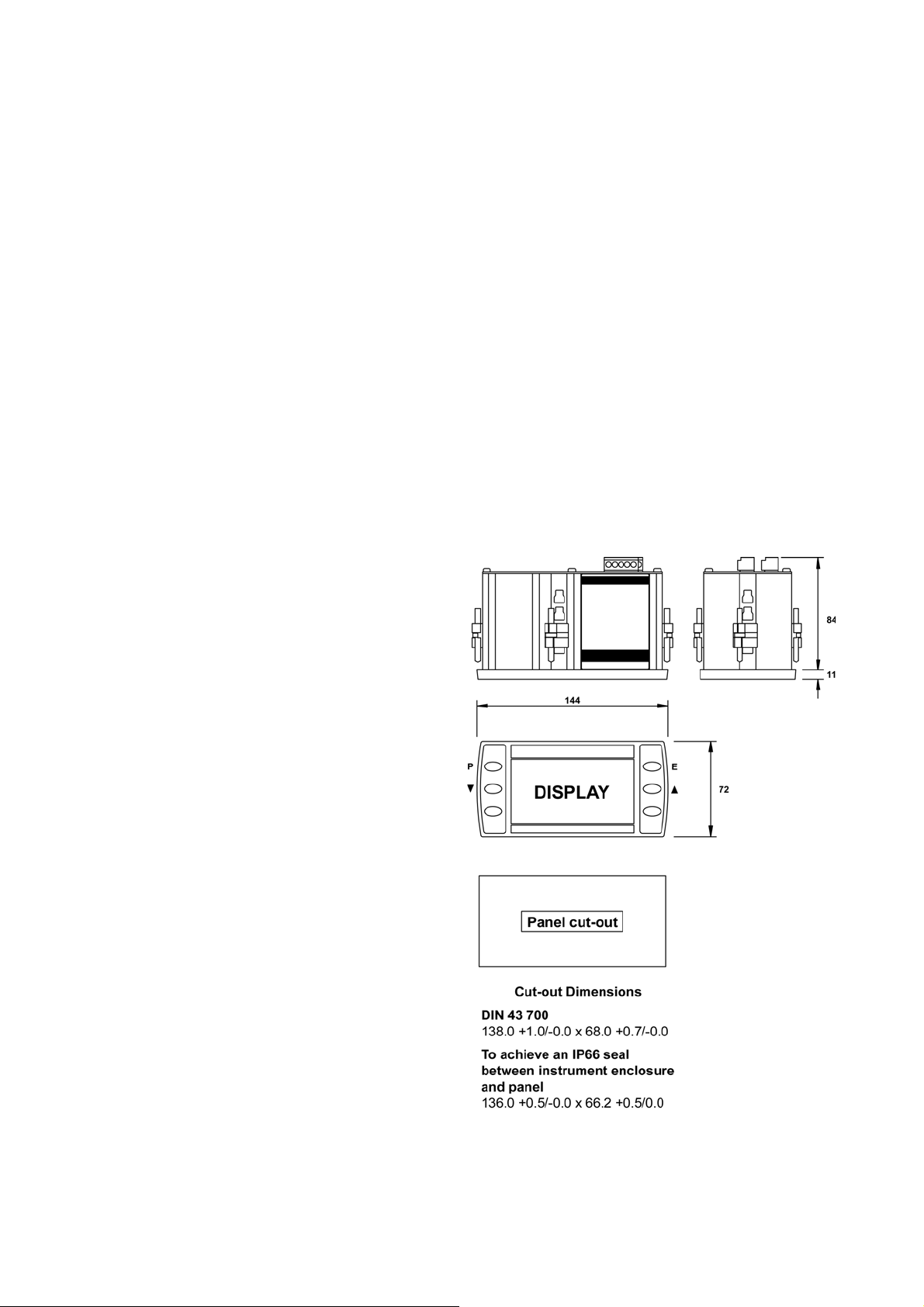
buttons see Fig 5.
Configuration and calibration via HARTmay be
performed using a portable configurator connected
directly to the BA478C or to the galvanic isolator
powering the transmitter, alternatively proprietary
configuration software operating on a personal
computer may be used. In addition to the
configuration functions available via the transmitter
push buttons, HARTcommunication enables loop
calibration and custom linearisation to be performed.
Details of the HARTcommunication are contained in
the BEKA HARTInterface Guide which may be
downloaded from www.beka.co.uk/manuals
7.1 Configuration menu
Throughout this manual the BA478C push buttons
are identified P E ▼▲and legends displayed by
the transmitter are shown within inverted commas
e.g. ‘CAL’ and ‘dEG’. Section 7.1.2 contains a
summary of each configuration function including a
cross reference to a more detailed description.
The functions contained in the configuration menu
vary depending upon the transmitter input selected,
see Figs 7, 8 & 9.
When the transmitter is being configured, the
transmitter 4/20mA output current is locked at the
value prior to entering the configuration menu.
When the optional alarms are fitted additional
functions are added to the configuration menu which
are described in section 10.3.
7.1.1 Access
Access to the configuration menu is obtained by
operating the Pand Ebuttons simultaneously. If the
transmitter is not protected by an access code the
first parameter 'InPut’ will be displayed. If the
transmitter is protected by an access code, ‘CodE’
will be displayed first. Pressing Pwill allow the four
digit security code to be entered digit by digit using
the or button to adjust the flashing digit and Pto
move control to the next digit. When the correct code
has been entered, pressing Ewill cause the first
parameter ‘InPut’ to be displayed. If an incorrect
code is entered, or no button is pressed for ten
seconds, the transmitter will automatically return to
the operating mode.
If the transmitter displays ‘LoC’ when the Pand E
buttons are operated simultaneously, the transmitter
push buttons have been locked by a HART
command - see the BEKA HARTInterface Guide
which may be downloaded from
www.beka.co.uk/manuals
7.1.2 Summary of functions
The functions that may be configured vary depending
upon the input selected.
Thermocouple and RTD inputs
The BA478C will always display sensor temperature.
Configuration allows:
Digital display units and resolution to be selected.
Bargraph display to represent required part of the
digital displayed range.
4/20mA output current to represent required part
of transmitter input range.
Voltage and resistance inputs
The BA478C can display the voltage or resistance
input in any engineering units.
Configuration allows:
Zero and span of digital display to be adjusted.
Bargraph display to represent required part of the
digital displayed range.
4/20mA output current to represent required part
of the transmitter input range.
Each of the functions in the configuration menu is
summarised below, including a cross-reference to a
more detailed description.
Transmitter Summary
display of function
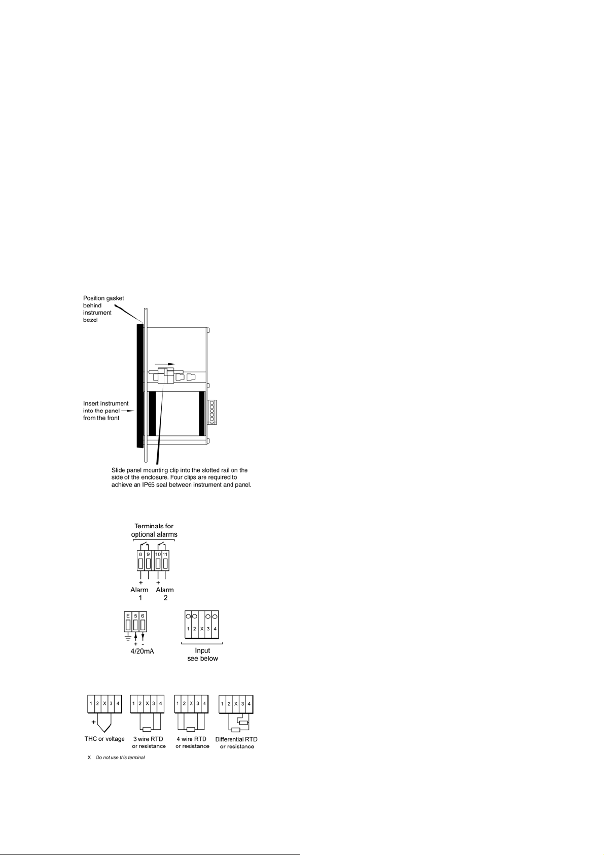
‘InPut’ Transmitter input
Selects one of the following inputs:
Thermocouple ‘tHC’
3 wire RTD ‘3rtd’
4 wire RTD ‘4rtd’
Differential RTD ‘d_rtd’
Voltage ‘Volt’
3 wire resistance ‘3rES’
4 wire resistance ’4rES’
See section 7.2.1
The content of the configuration menu depends upon
which transmitter input is selected, see following
summary and Figs 7, 8 and 9.