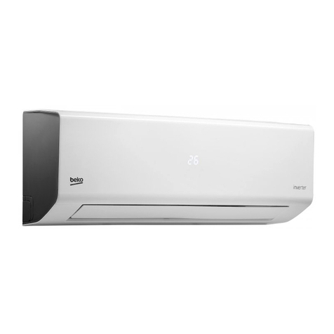
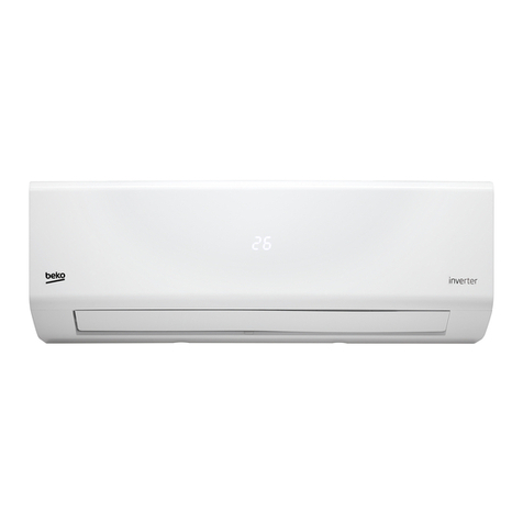
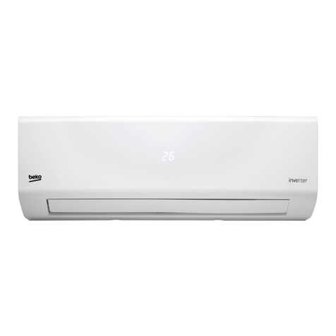
Beko BKFO 160 User manual

Air conditioner inverter
Installation manual
BKFO 160
EN IT

This product has been produced in environmentally friendly, modern facilities
Complies with the WEEE Regulation. Does not contain PCB.
Please read this user manual rst!
Dear Customer,
Thank you for preferrng a Beko product. We hope that you get the best results
from your product whch has been manufactured wth hgh qualty and state-of-
the-art technology. Therefore, please read ths entre user manual and all other
accompanyng documents carefully before usng the product and keep t as a
reference for future use. If you handover the product to someone else, gve the user
manual as well. Follow all warnngs and nformaton n the user manual.
Meanings of the symbols
Followng symbols are used n the varous secton of ths manual:
C
Important nformaton or
useful hnts about usage.
A
Warnng for hazardous
stuatons wth regard to lfe
and property.
Warnng to actons that must
never perform.
B
Warnng for electrc shock.
Warnng for danger of fre.
Warnng for hot surfaces.

Ar condtoner nverter / Installaton manual 3 / 48 EN
1 Safety nstructons 4
2 Installaton dagram & accessores 8
3 Selectng the nstallaton locaton 9
4 Outdoor unt nstallaton 10
4.1 Free space requred around outdoor unt (unt: mm) . . . . . . . . . . . . . . . . . . . . . . . . . . . . . . . . . . . . . . . . . . . . . 10
4.2 Installng the unt . . . . . . . . . . . . . . . . . . . . . . . . . . . . . . . . . . . . . . . . . . . . . . . . . . . . . . . . . . . . . . . . . . . . . . . . . . . . . . . . . 12
4.3 Mountng arrangement of dran socket. . . . . . . . . . . . . . . . . . . . . . . . . . . . . . . . . . . . . . . . . . . . . . . . . . . . . . . . . . . 12
4.4 Outdoor wre connecton and outdoor power supply cord connecton . . . . . . . . . . . . . . . . . . . . . . . . . . . 12
4.5 Electrcal wrng dagram. . . . . . . . . . . . . . . . . . . . . . . . . . . . . . . . . . . . . . . . . . . . . . . . . . . . . . . . . . . . . . . . . . . . . . . . . . 13
5 Indoor/outdoor unts connecton fnshng and test run 15
5.1 Flared connecton. . . . . . . . . . . . . . . . . . . . . . . . . . . . . . . . . . . . . . . . . . . . . . . . . . . . . . . . . . . . . . . . . . . . . . . . . . . . . . . . . 15
5.2 Flarng work. . . . . . . . . . . . . . . . . . . . . . . . . . . . . . . . . . . . . . . . . . . . . . . . . . . . . . . . . . . . . . . . . . . . . . . . . . . . . . . . . . . . . . . 16
5.3 Ppe connecton. . . . . . . . . . . . . . . . . . . . . . . . . . . . . . . . . . . . . . . . . . . . . . . . . . . . . . . . . . . . . . . . . . . . . . . . . . . . . . . . . . . .17
5.4 Purgingprocedures•leaktest . . . . . . . . . . . . . . . . . . . . . . . . . . . . . . . . . . . . . . . . . . . . . . . . . . . . . . . . . . . . . . . . . . . 18
6 Refrgerant flow dagram 20
7 Dsposal 21
8 Installaton nstructons 22
8.1 F-Gas nstructon. . . . . . . . . . . . . . . . . . . . . . . . . . . . . . . . . . . . . . . . . . . . . . . . . . . . . . . . . . . . . . . . . . . . . . . . . . . . . . . . . . 22
9 Specfcatons 23
Contents

4 / 48 EN Ar condtoner nverter / Installaton manual
The following should always be observed for safety
•
Please provde an exclusve crcut for the ar condtoner and make
sure that no other electrcal applances are connected to t.
•
Be sure to read <The followng should always be observed for
safety> before nstallng the ar condtoner.
•
Be sure to observe the cauton specfed here as they nclude
mportant tems related wth safety.
•
After readng ths manual, be sure to keep t together wth the
Instructon manual n a handy place on the customer's ste.
Warning
•
Dot not nstall the unt by yourself (customer).
Incomplete nstallaton could cause njury due to fre, electrc
shock, the unt fallng or leakage of water. Consult the dealer from
whom you purchased the unt or specal nstaller.
•
Install the unt securely n a place whch can bear the weght
of the unt.
When nstalled n an nsuffcent strong place, the unt could fall
and cause njury.
•
Use the specfed wres to connect the ndoor and outdoor
unts securely and attach the wres frmly to the termnal
block connectng sectons so that the stress of the wres s not
appled to the sectons.
Incomplete connectng and fxng could cause fre.
1 Safety nstructons

Ar condtoner nverter / Installaton manual 5 / 48 EN
1 Safety nstructons
•
Do not use ntermedate connecton of the power cord or the
extenson cord and do not connect many devces to one AC
outlet.
It could cause a fre or an electrc shock due to defectve contact,
defectve nsulaton ,exceedng the permssble current, etc.
•
Check that the refrgerant gas does not leak after nstallaton
has completed.
If refrgerant gas leaks ndoors, and comes nto contact wth the
fre of a fan heater, space heater, stove, etc., harmful substances
wll be generated.
•
Perform the nstallaton securely referrng to the nstallaton
manual.
Incomplete nstallaton could cause a personal njury due to fre,
electrc shock, the unt fallng or leakage of water.
•
Perform electrcal work accordng to the nstallaton manual
and be sure to use an exclusve crcut.
If the capacty of the power crcut s nsuffcent or there s
nsuffcent electrcal work, t could result n a fre or an electrc
shock.
•
Attach the electrcal cover to the ndoor unt and the servce
panel to the outdoor unt securely.
If the electrcal cover n the ndoor unt and/or the servce panel n
the outdoor unt are not attached securely, t could result n a fre
or an electrc shock due to dust water, etc.

6 / 48 EN Ar condtoner nverter / Installaton manual
•
Be sure to cut off the man power n case of settng up the
ndoor electronc control P. C. Board or wrng works.
It could cause an electrc shock.
•
The applance shall be nstalled n accordance wth natonal
wrng regulatons.
•
When nstallng or relocatng the unt, make sure that no
substance other than the specfed refrgerant (R410A)
enters the refrgerant crcut.
Any presence of foregn substance such as ar can cause abnormal
pressure rse or an exploson.
•
Perform earthng.
Do not connect the earth wre to a gas ppe, water ppe, lghtnng
rod or telephone earth wre. Defectve earthng could cause an
electrc shock.
•
Do not nstall the unt n a place where an nflammable gas
leaks.
If gas leaks and accumulates n the area surroundng the unt, t
could cause an exploson.
•
Fasten a flare nut wth torque wrench as specfed n ths
manual.
When fastened too tght, a flare nut may break after a long perod
and cause a leakage of refrgerant.
•
Install an earth leakage breaker dependng on the nstallaton
place (where t s humd).
1 Safety nstructons

Ar condtoner nverter / Installaton manual 7 / 48 EN
If a earth leakage breaker s not nstalled, t could cause an electrc
shock.
•
Check that the refrgerant gas does not leak after nstallaton
has completed.
If refrgerant gas leaks ndoors, and comes nto contact wth the
fre of a fan heater, space heater, stove, etc., harmful substances
wll be generated.
•
Perform the dranage/ppng work securely accordng to the
nstallaton manual.
If there s a defect n the dranage/ppng work, water could drop
from the unt and household goods could be wet and damaged.
1 Safety nstructons

8 / 48 EN Ar condtoner nverter / Installaton manual
Dran ppng for outdoor unt
•
Provde dran ppng before ndoor and outdoor connecton.
(It wll be hard to nstall dran socket, f ndoor unt becomes mmovable.)
•
Connect the dran hose (obtanable at a store, nsde dameter: 15mm) as shown n the fgure for
dranage.
A: Installaton plate
Putty
Ppe
Ppng tape
Ppe fxng band
Fxng screw
Dran hose
Dran hose
Dranage elbow
More than 350mm
More than 100mm
More than 100mm
More than 200mm f
there are obstacles to
both sdes.
More as a rule
More than 500mm f
the back ,both sdes
and top are open
B: Indoor unt
C: Wall hole cover
C
Note: Do not use the drain elbow in the cold region. Drain may freeze and it makes the
fan stop.
2 Installaton dagram & accessores

Ar condtoner nverter / Installaton manual 9 / 48 EN
Outdoor unt
•
Where t s not exposed to strong wnd.
•
Where arflow s good and dustless.
•
Where t s not exposed to ran and drect sunshne.
•
Where neghbours are not annoyed by operaton sound or hot ar.
•
Where rgd wall or support s avalable to prevent the ncrease of operaton sound or vbraton.
•
Where there s no rsk of combustble gas leakage.
•
Where t s at least 3m away from the antenna of TV set or rado. An amplfer may be requred for
the affected devce.
•
Install the unt horzontally.
•
Please nstall t n an area not affected by snowfall or blowng snow. In areas wth heavy snow,
please nstall a canopy, a pedestal and/or some baffle boards.
3 Selectng the nstallaton locaton

10 / 48 EN Ar condtoner nverter / Installaton manual
A
Warnng:
Avod the followng places for nstallaton where ar condtoner trouble s lable to
occur.
•
Where there s much machne ol.
•
Salty places such as seasde.
•
Where sulfde gas s generated such as a hot sprng.
•
Where there s hgh-frequency or wreless equpment.
C
Note:
When operating the air conditioner in low outside temperature, be sure to follow the
instruction describe below.
•
Never nstall the outdoor unt n a place where ts ar nlet/outlet sde may be exposed
drectly to wnd.
•
To prevent exposure to wnd, nstall the outdoor unt wth ts ar nlet sde facng the
wall.
•
To prevent exposure to wind, it is recommended to install a baffle board on the air outlet
side of the outdoor unit.
4.1 Free space requred around outdoor unt (unt: mm)
Obstacles
When there s an obstacle around the outdoor unt, t does not matter f the poston of the obstacle as
shown n the fgures below.
1. Obstacle over the top sde. 2. Obstacle n three drecton (but top sde s
open).
500 or more
100 or more
200 or more
100 or more 350 or more
4 Outdoor unt nstallaton

Ar condtoner nverter / Installaton manual 11 / 48 EN
3. Obstacle on front (blowng) sde only. In ths
case, the rear, both sde and top should be
open.
4. Obstacle on front and rear sde only. The unt
can be used by attachng an optonal outdoor
blowng gude (but both sdes and top are open).
500 or more
Blowng gude
500 or more
100 or more
5. Servce space
Keep the servce space as shown n the fgure below for mantenance
Servce space
500 or more
500 or more 350 or more
100 or more
100 or more
•
When nstallng the unt n an area that s enclosed on four sdes such as a verandah, be sure to leave
move than 200mm behnd the unt as shown.
•
When there s a lack of arflow or there s a possblty of becomng short cycle, nstall an outlet gude
and make sure there s enough space behnd the rear sde of the ar nlet.
C
Note: Make sure not to install several outdoor units sideways next to each other.
Wndow
More than
350mm
More than
100mm More than
200mm
More than 100mm
Less than 1,200 mm of the
front surface sde
More than 100mm
4 Outdoor unt nstallaton

12 / 48 EN Ar condtoner nverter / Installaton manual
4.2 Installng the unt
•
Be sure to fx the unt's legs wth bolts when nstallng t.
•
Be sure to nstall the unt frmly to ensure that t does not fall by earthquake or gust.
4.3 Mountng arrangement of dran socket
Please perform the dran ppng work only when dranng from one place.
A
Warnng: Do not use dran socket and dran cap n the cold regon. Dran may freeze
and t makes the fan stop.
4.4 Outdoor wre connecton and outdoor power supply cord
connecton
•
Be sure to lead n the power supply cord to the ar condtoner n accordance wth the specfcaton
tables below and "Techncal Standards for Electrcal Installaton".
•
Be sure to use specal crcuts for room ar condtoner.
•
Connect to the power swtch whch has a gap of 3mm or more then open to nterrupt the source
power phase.
•
When the power swtch s shut off, t must nterrupt all phases. Input capacty Man swtch/Fuse: 20A
Power supply cord specfcaton Cable 3-core 2.5mm2, n conformty wth Desgn 245 IEC 57.
Indoor and outdoor connectng
wre specfcaton Cable 4-core 0.75mm2, n conformty wth Desgn 245 IEC 57.
A
Warnng: Attach an earth leakage breaker accordng to your nstallaton locaton. If any
breaker s not attached, t may cause a rsk of electrc shock.
4 Outdoor unt nstallaton

Ar condtoner nverter / Installaton manual 13 / 48 EN
4.5 Electrcal wrng dagram
1
(L)
2
(N)
2
(N)
3
( )
1
(L)
3
( )
0
0
Indoor unt
Indoor unt B
Outdoor unt
To power
Mult splt outdoor unt
Power
termnal
panel Connecton
termnal
panel A
Connecton
termnal
panel B
Indoor unt A
C
Note: For multi split and one for one common indoor unit the wiring diagram.
A
Warnng:
Be sure to comply wth "Techncal Standards for Electrcal Installaton", follow ths
manual and use specal crcuts for electrcal work. If there s a lack of crcut capacty or
some defcency n nstallaton, t may cause a rsk of electrc shock.
Overcurrent mght be produced may nclude DC substances. Be careful to choose the
correct type of overcurrent protecton swtch.
4 Outdoor unt nstallaton

14 / 48 EN Ar condtoner nverter / Installaton manual
1(L) 2(N) 3
1(L) 2(N) 4(SI)1(L) 2(N) 4(SI)
Power termnal
panel
Cable clamp
Power cord To ndoor unt A To ndoor unt B
Connecton
termnal
panel A
Connecton
termnal
panel B
1. Remove the screw of termnal cover.
2. Connect the wre and power supply cable to the termnal block.
3. Replace the termnal cover securely.
A
Warnng:
-
Be sure to attach the valve cover of the outdoor unt securely, otherwse t may result
n a fre or an electrc shock from dust or water.
-
Use the ndoor/outdoor unt connectng wre that meets the standards to connect
the ndoor and outdoor unts and fx the wre to the termnal block securely so
that no external force s conveyed to the connectng secton of the termnal block.
Incomplete connectons or fxng of the wre could result n a fre.
-
Be sure to attach the termnal block cover on both ndoor and outdoor unts. If the
termnal block cover s ncorrectly attached, t may cause a rsk of fre or electrc shock
due to dust or water penetraton.
-
Be sure to use the power cord whch type s more than 20A, otherwse t may result
n a fre.
4 Outdoor unt nstallaton

Ar condtoner nverter / Installaton manual 15 / 48 EN
5.1 Flared connecton
Ppe length and heght dfference
Lmts Type
Ppe length per ndoor unt 20m*
Total ppe length for mult-system 40m
Heght dfference (I.D ~ O.D) 10m
Heght dfference (I.D ~ I.D) 7.5m
*
Do your best to reduce the ppe length. Long ppe may cause capacty of the ndoor unt
nclne.
Refrgerant adjustment: If total ppe length exceeds 15m, addtonal refrgerant (R410A) charge s
requred. (The outdoor unt s charged wth refrgerant for total ppe length up to 15m. )
Ppe length and heght dfference
Ppe length Up to 15m No addtonal charge s requred.
Exceedng 15m Addtonal charge s requred.
Refrgerant to be added 15g/m × (refrgerant ppng length (m)-15)
Ppe sze
If you use commercally avalable copper, use the followng table for specfcatons.
Valve sze for outdoor unt Wall thckness Insulaton thckness
ALqud ppe Ø6.35mm 0.8mm 8mm
Gas ppe Ø9.52mm 0.8mm 8mm
BLqud ppe Ø6.35mm 0.8mm 8mm
Gas ppe Ø9.52mm 0.8mm 8mm
A
Warnng:
Be sure to use the nsulaton of specfed thckness. Excessve thckness may cause
ncorrect nstallaton of ndoor unt and lack of thckness may cause dew drppage.
5 Indoor/outdoor unts connecton fnshng and
test run

16 / 48 EN Ar condtoner nverter / Installaton manual
5.2 Flarng work
Main cause of gas leakage is defect in flaring work. Perform flaring work correctly in the following
procedure.
1. Ppe cuttng
•
Cut the cooper ppe correctly wth ppe cutter.
2. Burrs removal
•
Completely remove all burrs from the cut cross secton of the ppe.
•
Put the end of the copper ppe downward to prevent burrs from droppng n the ppe.
3. Puttng nut on
•
Remove flare nuts attached to ndoor and outdoor unts, then put them on ppe havng completed
burr removal.
(Not possble to put them on after flarng work).
•
Flare nut for R410A ppe may dffer from R22 ppe dependng on the dameter of ppe.
4. Flarng work
•
Perform flarng work usng flarng tool as shown below.
Outsde dameter
A (mm)
Flare tool for R410A
clutch type
Conventonal flare tool
Clutch type Wng nut type
Ø6.35mm 0 to 0.5 1.0 to 1.5 1.5 to 2.0
Ø9.52mm 0 to 0.5 1.0 to 1.5 1.5 to 2.0
Ø12.7mm 0 to 0.5 1.0 to 1.5 2.0 to 2.5
Ø15.88mm 0 to 0.5 1.0 to 1.5 --
Frmly hold copper ppe n a de n the dmenson shown n the table above.
5. Check
•
Compare the flared work wth the fgure below.
•
If flare s noted to be defectve, cut off the flared secton and perform flarng work agan.
5 Indoor/outdoor unts connecton fnshng and
test run

Ar condtoner nverter / Installaton manual 17 / 48 EN
o
90
No good
Good Tlted Uneven Burred
Flare nut
Copper ppe
Copper ppe
Burr
Flarng tool
Clutch type
York
De
Flare nut
De
Copper ppe Copper ppe
Wng nut type
Insde s shnng wthout any scratches
Smooth all around
Ppe cutter
Spare
reamer
5.3 Ppe connecton
C
Note: Fasten a flare nut with a torque wrench as specified in the table below. When
fastened too tight, a flare nut may be broken after a long period and cause a leakage of
refrigerant.
1. Indoor unt connecton
•
Connect both lqud ppe and gas ppe to ndoor unt.
-
Apply a thn coat of refrgeraton ol to the seat surface of ppe.
-
For connecton, algn the center of both ppe and unon, then tghten the frst 3 to 4 turns n flare
nut by hand.
-
For tghtenng the unon part of the ndoor unt sde, use the table below as a standard and tghten
the flare nut wth two wrenched. Excessve tghtenng damages the flared secton.
5 Indoor/outdoor unts connecton fnshng and
test run

18 / 48 EN Ar condtoner nverter / Installaton manual
Ppe dameter Tghtenng torque
N•m Kgf•cm
Ø6.35mm 13.7 to 17.7 140 to 180
Ø9.52mm 34.3 to 41.2 350 to 420
Ø12.7mm 49.0 to 56.4 500 to 575
Ø15.88mm 73.5 to 78.4 750 to 800
2. Outdoor unt connecton
•
Connect ppe to the ppe jont part of the stop valve n the same method as the ndoor unt.
-
For tghtenng, use the same tghtenng torque appled for ndoor unt and tghten the flare nut
wth torque wrench or spanner.
Insulaton and tapng
•
Cover ppng jonts wth ppe cover.
•
For outdoor unt sde, surely nsulate every ppng ncludng valves.
•
Usng ppng tape, apply tapng startng from the entry of outdoor unt.
-
Fx the end of ppng tape wth adhesve tape.
-
When ppng has to be arranged through above celng, closet or area where temperature and
humdty are hgh, wnd addtonal commercally sold nsulaton for preventon of condensaton.
5.4 Purging procedures • leak test
1. Purgng procedures
1. Connect the refrgerant ppes (both lqud ppe and gas ppe) between the ndoor unt and the
outdoor unt.
2. Remove the servce port cap of the stop valve on the gas ppe sde of the outdoor unt. (The stop
valve wll not work n ts ntal state fresh out of the factory [totally closed wth cap on].)
3. Connect the gauge manfold valve and vacuum pump to the servce port of the stop valve on the
gas ppe sde of the outdoor unt
4. Run the vacuum pump. Vacuumze for more than 15 mnutes.
5. Check the vacuum wth the gauge manfold valve, then close the gauge manfold valve and stop
the vacuum cap.
6. Leave t as s for one or two mnutes. Make sure the ponter of the gauge manfold valve remans
n the same poston. Confrm that the pressure gauge shows -0.101MPa or -760mmHg.
7. Remove the gauge manfold valve quckly from the servce port of the stop valve.
5 Indoor/outdoor unts connecton fnshng and
test run

Ar condtoner nverter / Installaton manual 19 / 48 EN
8. After refrgerant ppes are connected and evacuated, fully open all stop valves on both sdes of
gas ppe and lqud ppe.
9. Ppe length up to 15m, no gas charge s needed.
Ppe length exceedng 15m, charge the prescrbed amount of gas.
10.Tghten the cap to the servce port to obtan the ntal status.
11. Retgten the cap.
12.Leak test.
C
Note: Each set of pipes must be purged individually.
Compound pressure
gauge (for R410A)
Pressure gauge
(for R410A)
Gauge manfold Valve
(for R410A)
Handle Hgh
Wndow
Handle Low
-0.101MPa
(-760 mmHg)
Charge hose
(for R410A)
(Or the vacuum pump
wth the functon
to prevent the back
flow)
Adapter for
preventng
the back flow
5 Indoor/outdoor unts connecton fnshng and
test run

20 / 48 EN Ar condtoner nverter / Installaton manual
Outdoor untIndoor unt
Coolng cycle
Heatng cycle
Indoor heat exchanger- A
Accumulator
Outdoor heat exchanger
Compressor
Indoor heat exchanger- B
4-way valve
Unt A
Unt A
Unt B
Unt B
Flter
Packng lst
Outdoor unt
No. Name Amount
1. Outdoor unt 1
2. Dranage below* 1
3. Manual 1
The symbol "*" stands for the part to be pcked and made purchase.
6 Refrgerant flow dagram
This manual suits for next models
1
Table of contents
Languages:
Other Beko Air Conditioner manuals

Beko
Beko BDIN 091 User manual

Beko
Beko BP109C User manual

Beko
Beko Room Air Conditioner User manual

Beko
Beko 10M-8899243200-4921-01 User manual

Beko
Beko BFYH 500 User manual

Beko
Beko BMVIF 120 User manual

Beko
Beko BS 107 CN User manual

Beko
Beko BEWPI 090 User manual

Beko
Beko BEVPI 120 User manual

Beko
Beko BEVPI 090 User manual
Popular Air Conditioner manuals by other brands

Samsung
Samsung AW05F05EA Owner's instructions

Toshiba
Toshiba RAV-RM561KRTP-E installation manual

Arcoaire
Arcoaire R4A3 installation instructions

ALPATEC
ALPATEC AC 12 FIT user manual

Daikin
Daikin Comfort Flex CLIV Series Installation, operation and maintenance manual

Bard
Bard THE WALL-MOUNT WA3S3-A installation instructions