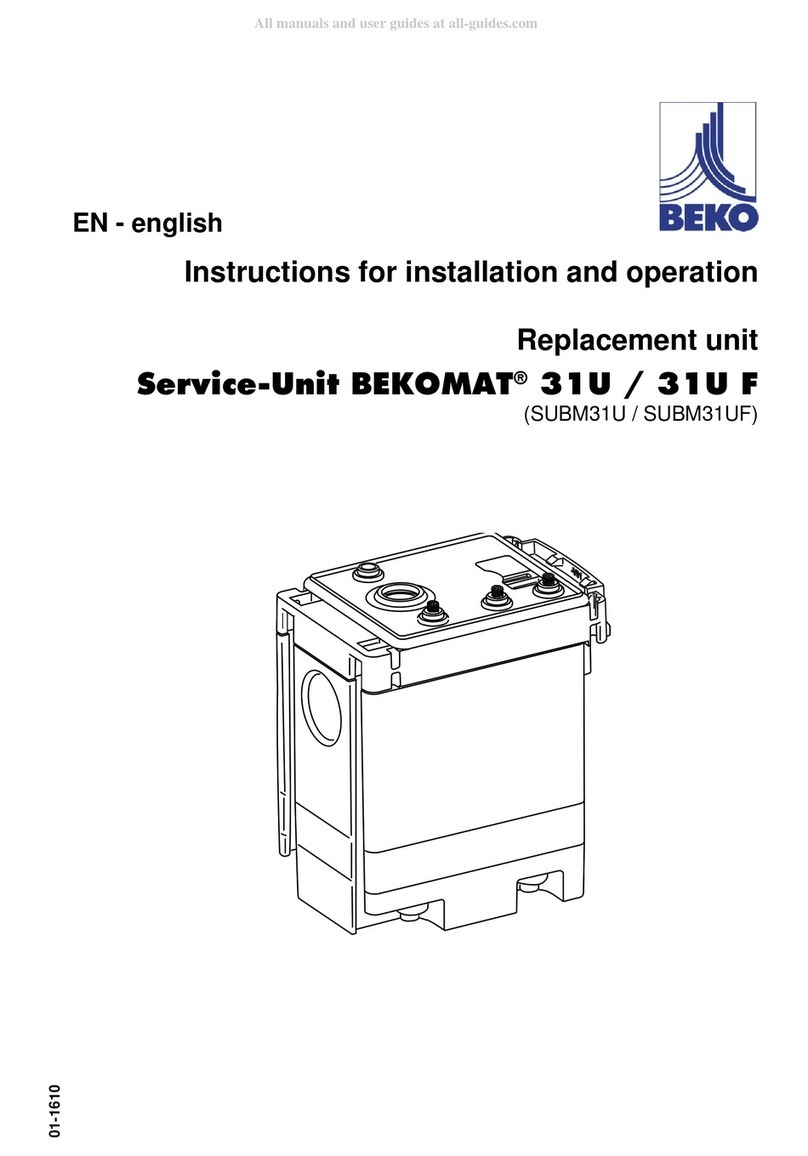
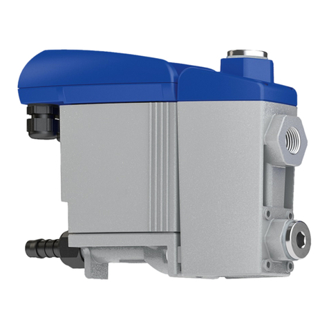
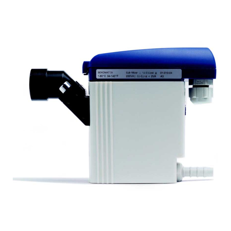
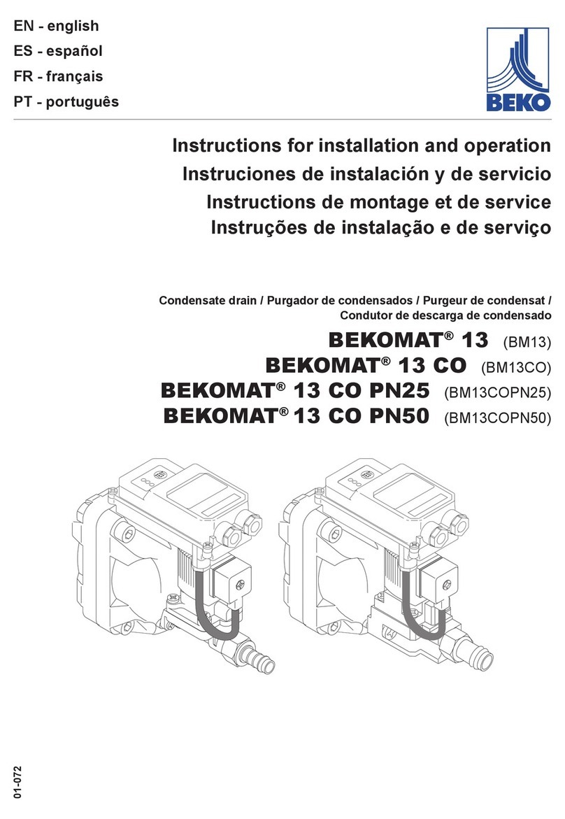
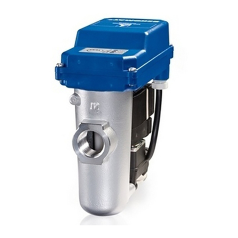
Beko BEKOMAT 3 E Ex User manual

BEKOMAT®3 E Ex
BEKOMAT®6 E Ex
BEKOMAT®3 CO Ex
BEKOMAT®6 CO Ex
EN- English
01-3005
Condensate drain
ll 2G Ex ib llB T4 Gb
BVS 03 ATEX E 214 X
Installation and operating manual

Installation and operating manual EN
2 BEKOMAT®3/6 CO Ex, 3/6 E Ex

EN Installation and operating manual
BEKOMAT®3/6 CO Ex, 3/6 E Ex 3
Contents
1. Safety information........................................................................................................................................... 4
1.1. Pictograms and symbols ........................................................................................................................... 4
1.1.1. In this document............................................................................................................................. 4
1.1.2. On the unit...................................................................................................................................... 4
1.2. Signal words according to ISO 3864 and ANSI Z.535............................................................................... 4
1.3. General safety instructions........................................................................................................................ 5
1.4. Transport and storage ............................................................................................................................... 7
1.5. Proper use................................................................................................................................................. 8
1.6. Warranty and liability ................................................................................................................................. 8
2. Product information ........................................................................................................................................ 9
2.1. Type plate.................................................................................................................................................. 9
2.2. Product overview and description ............................................................................................................. 9
2.3. Control and display elements .................................................................................................................. 10
2.4. Function................................................................................................................................................... 11
2.5. Dimensions.............................................................................................................................................. 12
2.5.1. BEKOMAT®3 CO/E Ex ................................................................................................................ 12
2.5.2. BEKOMAT®6 CO/E Ex ................................................................................................................ 12
2.6. Technical data ......................................................................................................................................... 13
2.6.1. Identication of explosion-proof equipment according to ATEX and EPL .................................... 14
3. Installation...................................................................................................................................................... 14
3.1. Warning ................................................................................................................................................... 14
3.2. Example of installation ............................................................................................................................ 15
3.3. Installation ............................................................................................................................................... 16
4. Electrical installation..................................................................................................................................... 18
4.1. Installation instructions ............................................................................................................................ 18
4.2. Wiring diagram ........................................................................................................................................ 19
4.3. Electrical connections.............................................................................................................................. 20
4.4. Potential equalisation .............................................................................................................................. 21
4.5. NAMUR interface .................................................................................................................................... 21
5. Commissioning.............................................................................................................................................. 21
6. Operation........................................................................................................................................................ 22
7. Maintenance and servicing........................................................................................................................... 23
7.1. Maintenance schedule ............................................................................................................................ 23
7.2. Cleaning device....................................................................................................................................... 23
7.3. Spare parts.............................................................................................................................................. 24
7.4. Accessories ............................................................................................................................................. 24
8. Troubleshooting and repair.......................................................................................................................... 25
9. Decommissioning.......................................................................................................................................... 25
10. Dismantling and disposal........................................................................................................................... 25
11. Declaration of Conformity........................................................................................................................... 26

Installation and operating manual EN
4 BEKOMAT®3/6 CO Ex, 3/6 E Ex
1. Safety information
1.1. Pictograms and symbols
1.1.1. In this document
General instruction
Observe installation and operating instructions
General hazard symbol (danger, warning, caution)
Warning regarding potentially explosive substances / risk of explosion
General hazard symbols (danger, warning, caution) relating to mains voltage and powered
machine parts
1.1.2. On the unit
ATEX mark
Observe installation and operating instructions
(on type plate)
1.2. Signal words according to ISO 3864 and ANSI Z.535
DANGER Imminent danger
Consequences of non-compliance: serious or fatal injury
WARNING Potential danger
Consequences of non-compliance: possible serious or fatal injury
CAUTION Imminent danger
Consequences of non-compliance: possible injury and/or damage to property
NOTE Additional notes, tips and hints
Consequences of non-compliance: inecient operation, extra maintenance work.
No risk to persons.

EN Installation and operating manual
BEKOMAT®3/6 CO Ex, 3/6 E Ex 5
1.3. General safety instructions
DANGER Risk of explosion
Risk to life from explosion, ash re or combustion
• On sites where there is a risk of explosion or combustion, all necessary measures for the
safe operation of the machine, auxiliary devices and components must be taken.
• Observe all applicable rules and regulations for all work on and with the unit, including
operation and maintenance
(e.g. ATEX, CENELEC, NEC, TRBS, national guidelines and regulations).
• Ignition sources must not be brought into areas where there is a risk of explosion or
combustion.
• If this cannot be avoided, all necessary measures to prevent a re or explosion must be
taken.
DANGER Insucient qualication
Improper handling and operation of the unit can result in serious or even fatal injury, and/or
damage to property.
• All tasks described in this installation and operating manual must be performed by
specialist technical personnel1 who meet the following criteria:
• Before carrying out any work with or on the device, all specialist technical personnel¹
must have read and understood the contents of this installation and operating manual.
DANGER Escaping compressed gas
Risk of serious or even fatal injury from suddenly released compressed gas or condensate at
bursting and/or unsecured device components.
• Before carrying out any assembly, installation or maintenance work, depressurise
the system. All electrical work must be carried out by authorised specialist technical
personnel1only.
• Use only pressure-resistant installation materials and suitable tools that are in proper
working order.
• Before pressurising the system, check all unit parts and repair them, if necessary. To
prevent pressure blows during unit operation, open all valves slowly.
• Make sure that no persons can be injured or objects can be damaged by condensate or
escaping compressed gas.
• Protect the unit parts against vibration and impact.
• Perform a leakage test.
DANGER Mains voltage
Risk of serious or even fatal injury from electric shock when coming into contact with non-
insulated, powered components.
• For the electrical installation of the unit, adhere to all applicable regulations (e.g. VDE
0100 / IEC 60364).
• Before carrying out any maintenance work, de-energize the system.
• All electrical work must be carried out by authorised specialist technical personnel1only.
WARNING Operation of unit outside limit range
If the specied limits are exceeded, there is a risk of device malfunction, potentially resulting
in injury and damage to materials.
• The unit must only be operated for the intended purpose and within the permissible limits
specied on the type plate and in the technical data.
• Strictly adhere to the prescribed operating times and maintenance intervals.
1 Specialist technical personnel
Specialist technical personnel are persons who, due to their professional qualication and knowledge in the eld
of measuring, control and pneumatic technology, and their knowledge of the applicable statutory regulations,
guidelines and standards are in a position to foresee potential dangers in relation to the use of the device and
who are qualied to perform the tasks described in this manual. Special operating conditions (e.g. aggressive
media) require additional knowledge. In addition, observe the requirements for "qualied persons" as laid down
in the Technical Rules on Operational Safety (TRBS). It is the responsibility of the plant owner to ensure that the
instructions in this manual are adhered to.

Installation and operating manual EN
6 BEKOMAT®3/6 CO Ex, 3/6 E Ex
NOTE Warranty and liability
Claims made with reference to warranty and liability shall only be deemed valid if the
following instructions are strictly adhered to:
• Do not make any modications to the unit!
• Use only original spare parts and accessories!
• Strictly observe the installation and operating instructions!
• Use the unit only for the intended purpose.
For more information on warranty and liability, see 1.6, page 8.
NOTE Installation and operating manual
First make sure that the installation and operating manual actually refers to your device type.
This document contains important information and instructions for the safe operation of the
device. Before carrying out any work with or on the device, all specialist technical personnel ¹
must have read this manual.
A copy of this installation and operating manual must be kept near the device where it is at
all times accessible to sta.
In addition to the instructions in this document, always comply with the statutory regulations
for machine operation, accident prevention and safety. This also applies to the use of
accessories and spare parts.
1 Specialist technical personnel
Specialist technical personnel are persons who, due to their professional qualication and knowledge in the eld
of measuring, control and pneumatic technology, and their knowledge of the applicable statutory regulations,
guidelines and standards are in a position to foresee potential dangers in relation to the use of the device and
who are qualied to perform the tasks described in this manual. Special operating conditions (e.g. aggressive
media) require additional knowledge. In addition, observe the requirements for "qualied persons" as laid down
in the Technical Rules on Operational Safety (TRBS). It is the responsibility of the plant owner to ensure that the
instructions in this manual are adhered to.

EN Installation and operating manual
BEKOMAT®3/6 CO Ex, 3/6 E Ex 7
1.4. Transport and storage
Despite our best eorts regarding packaging, etc., the device is susceptible to damage during transport. Upon
receipt, please remove all packaging material and inspect the device for visible damage. If you detect any such
damage, immediately notify the carrier company and BEKO TECHNOLOGIES GMBH or one of its agents.
CAUTION Damage caused during transport or storage
Incorrect transport or storage, or the use of unsuitable lifting equipment might cause damage
to the device.
• The unit must only be transported and stored by authorised and suitably trained technical
personnel.
• If you detect any damage, do not start the device.
• Always adhere to the specied transport and storage temperatures.
• Protect the unit against direct sunlight and heat radiation.
The device must be stored in the original
packaging. Seal the packaging and store it
in a dry and frost-free room. Ensure that the
storage temperature does not exceed the
limits specied on the type plate.
Even when packaged, take suitable
measures to protect the device against the
elements.
While in storage, secure the device so that
it cannot topple over or fall, and protect it
against vibration.
NOTE Recycling of packaging material
• The packaging material is recyclable. Dispose of the packaging material according to the
applicable statutory regulations.

Installation and operating manual EN
8 BEKOMAT®3/6 CO Ex, 3/6 E Ex
1.5. Proper use
The BEKOMAT® is an electronically level-controlled condensate drain for compressed air systems. The BEKOMAT®
is able to drain condensate from the plant components at operating pressure and with virtually no compressed air
loss. The BEKOMAT® version with no-load drain/no-load valve caters for plants with low operating pressure, for
instance in connection with multi-stage compressors.
This model must always be equipped with original spare parts and accessories.
The BEKOMAT®3/6 CO Ex or 3/6 E Ex can be operated in potentially explosive atmospheres, provided that the
unit bears the following ATEX-/EPL mark:
II 2G Ex ib IIB T4 Gb
Admissible media: Ethane, methane, coal gas (town gas), compressor oils, diesel fuel, ethylene,
propane, heating oil, uid of DGRL group ll
For more information regarding the ATEX classication and mark, see 2.6.1, page 14.
Do not install the BEKOMAT® in areas that are exposed to frost.
Operate the unit only for the intended purpose and within the limit range specied in the technical data. Do not
operate the unit with any media (uids, gas/vapour mixtures) than those listed above. Any other use of the unit is
deemed improper and poses a risk to persons, property and the environment.
1.6. Warranty and liability
All warranty shall be voided, if the BEKOMAT® is used improperly, for a purpose other than the intended or is
operated outside the limits specified in the technical data. In such cases, the manufacturer shall also reject any
liability for damage. Improper operation includes:
• Incorrect installation, commissioning or operation; insucient maintenance
• Operation with defective components
• Non-compliance with the instructions in this document, in particular the safety instructions
• Modication of the unit
• Use of third-party spare parts that have not been approved by the manufacturer

EN Installation and operating manual
BEKOMAT®3/6 CO Ex, 3/6 E Ex 9
2. Product information
2.1. Type plate
The type plate is attached to the device housing. It contains all relevant technical data of the BEKOMAT® . Please
have these details to hand when contacting the manufacturer or supplier:
Kondensatableitersteuerung
Condensate drain control
Commande électronique au purgeur
No.: BVS 03 ATEX E 214 X
ll 2G Ex ib llB T4 Gb
Umax = 12,6 VDC / Imax = 150 mA
No
QM
Nur für bescheinigte, eigengesicherte Stromkreise.
Only for certied, intrinsically safe circuits.
Seulement pour des circuits de securité intrinsèque certiés.
BEKO TECHNOLOGIES GMBH
Im Taubental 7, 41460 Neuss 0158
Designation Description
No.: BVS 03 ATEX E 214 X Type approval certicate
ll 2G Ex ib llB T4 Gb ATEX / EPL marking
Umax= 12.6 VDC Max. supply voltage
Imax= 150 mA Max. short circuit current
NOTE Type plate
Do not remove or cover the type plate and protect it against damage.
2.2. Product overview and description
2
3
54
6
1
2
3
54
6
1
1
Upper condensate inlet/venting line
5
Electronics housing
2
Centre condensate inlet
6
Condensate discharge/solenoid valve
3
Lower condensate inlet
4
Solenoid valve

Installation and operating manual EN
10 BEKOMAT®3/6 CO Ex, 3/6 E Ex
2.3. Control and display elements
The control and display elements of the BEKOMAT®are integrated into the electronics housing.
BEKO TECHNOLOGIES
www.beko-technologies.com
BEKOMAT ®
ALARM / TEST
NETZ / POWER
TEST
1 2
1
Alarm /test LED
Indicates the current system state of the BEKOMAT®.
2
Test button
Press this button to depressurise or manually drain the BEKOMAT®.
NOTE No permanent drainage
Do not use the test button for permanent drainage!
ALARM / TEST
NETZ / POWER
TEST Alarm/test LED o
BEKOMAT®is not powered.
ALARM / TEST
NETZ / POWER
TEST Alarm /test LED lit
BEKOMAT®is powered and running in normal operating mode.
ALARM / TEST
NETZ / POWER
TEST Alarm /test LED ashing
BEKOMAT® is in alarm mode or test button has been pressed.
Alarm mode:
The BEKOMAT® is continuously monitored by electronic and sensory devices. If a fault or malfunction occurs, the BEKOMAT® is
automatically switched to alarm mode (e.g. due to blocked condensate discharge, or overload). In alarm mode, the solenoid valve is
automatically opened, starting in cycle mode in order to eliminate the problem. If the problem persists for more than one minute, the
red alarm LED flashes and the optocoupler output is switched. The valve is then repeatedly opened every four minutes for 7.5 seconds,
until the problem is resolved automatically or by servicing the unit. After the problem has been resolved, the BEKOMAT®automatically
switches to normal operating mode.
1 min
4 min
Ventil
Alarm-LED
Optokoppler-
Ausgang
Alarmmodus
7,5 s 7,5 s 7,5 s
4 min 4 min3 min
NOTE Additional information
For additional information regarding the function of the BEKOMAT®, see function 2.4, page
11.

EN Installation and operating manual
BEKOMAT®3/6 CO Ex, 3/6 E Ex 11
2.4. Function
From an operating pressure of ≥ 0.8/1.2, the condensate is drained through the solenoid valve
4
. The condensate
ows through the upper condensate inlet
1
and is collected in the container
3
.
1
2
3
4
5
The capacitive dual sensor
2
monitors the lling level in the container. If a certain lling level is reached, the
solenoid valve
4
is opened and the condensate is discharged through the condensate discharge
5
.
1
2
3
4
5

Installation and operating manual EN
12 BEKOMAT®3/6 CO Ex, 3/6 E Ex
2.5. Dimensions
2.5.1. BEKOMAT®3 CO/E Ex
200 (7.8)
140 (5.5)
23 (0.9)
128 (5.0)
235 (9.2)
ca 255 (10.0)
160 (6.2)
G¾-a
(¾NPT-a)
(½NPT-i)
G½-i
G¼-i
(¾NPT-a)
G¾-a
mm (inch)
i = innen/inside
a = außen/outside
2.5.2. BEKOMAT®6 CO/E Ex
29 (1.1)
135 (5.3)145 (5.7)
194 (7.6)
117 (4.6)
ca. 295 (11.6)
40 (1.6) 20 (0.8)
30 (1.1)
179 (7)
49 (1.9)
35,5 (1.4)
mm (inch)
i = innen/inside
M6
Einschraubtiefe
Thread depth
10 (0.4)
(¾“ NPT-i)
G¾-i
G1-i
(1“ NPT-i)
G½-i (½“ NPT-i)
(½“ NPT-i)
G½-i

EN Installation and operating manual
BEKOMAT®3/6 CO Ex, 3/6 E Ex 13
2.6. Technical data
General data
3 CO Ex 3 E Ex 6 CO Ex 6 E Ex
Device group ll
Device category 2G
Ignition protection type ib
Explosion group llB
Temperature class T4
Device protection level Gb
Min. / max. storage/transport temperature +1 ... +60 °C
Min. / max. ambient temperature +1 ... +60 °C
Min. / max. media temperature +1 ... +60 °C
Condensate inlet
3 x G¾-inside
(optional: NPT tting)
2 x G¾-inside
(optional: NPT tting)
1 x G1-inside
(optional: NPT tting)
Condensate discharge
1 x G½-inside (optional: NPT tting)
Condensate
oil-contaminated
condensate
| oil-free
condensate
oil-contaminated
condensate |
oil-free, possibly
aggressive
condensate
oil-contaminated
condensate
| oil-free
condensate
oil-contaminated
condensate |
oil-free, possibly
aggressive
condensate
Weight 3.4 kg (empty) 8.0 kg (empty) 6.7 kg (empty)
14.0 kg (empty)
Materials
Housing:
aluminium,
hard-coated
Housing:
Stainless steel
Housing:
aluminium,
hard-coated
Housing:
Stainless steel
Performance data
3 CO Ex 3 E Ex 6 CO Ex 6 E Ex
Max. compressor capacity
100 m³/min
e.g. Central/Southern Europe,
Central America
1000 m³/min
e.g. Central/Southern Europe,
Central America
Max. refrigeration dryer performance
200 m³/min
e.g. Central/Southern Europe,
Central America
2000 m³/min
e.g. Central/Southern Europe,
Central America
Max. drainage rate (short-term) 540 l/h 1700 l/h
Ø drainage rate 43 l/h 274 l/h
Min./max. operating pressure 0.8 ... 16 … 1.2 bar 16 bar (see type plate)
Electrical data
3 CO Ex 3 E Ex 6 CO Ex 6 E Ex
Operating voltage
(connection to intrinsically safe power supply as specied below)
Urated = 12.0 V / Umax = 12.6 V
Imax = 150 mA / Pmax = 1.9 W
Power consumption P ≤ 1.9 W
Recommend wire cross-section 3 x 0,75 ... 1.5 mm² (AWG 16 ... 20)
Protection class IP 65
Recommended power supply
Power supply unit
85 - 230 VAC
4005140
Alarm output
Optocoupler output for signalling to a NAMUR interface accord-
ing to DIN EN 60947-5-6
Recommended switch amplier
230 VAC for BEKOMAT®Ex 4006591
Solenoid valve
EN 60079-0:2012 + A11
EN 60079-11:2012
ll2G Ex ia llC T6 or Ex ia ll T5
PTB 01 ATEX 2101
0158 IP 65
II 2G Ex ib IIB T4 Gb

Installation and operating manual EN
14 BEKOMAT®3/6 CO Ex, 3/6 E Ex
2.6.1. Identication of explosion-proof equipment according to ATEX and EPL
ll Device group ll
Suitable for use in industrial areas with potentially explosive atmosphere; not for use in mines
2G Device category 2G
Suitable for use in areas in which an atmosphere at risk of explosion as a mixture of air and inammable gases, vapours or
mists can form occasionally during normal operation (zones 1 and 2).
Ex ib Ignition protection type ib - intrinsically safe
Intrinsically safe according to EN 60079-11
llB Explosion group IIB
Suitable for gases and vapours with a standard gap width of 0.5 - 0.9 mm and a minimum ignition current ratio of
0.45 - 0.8.*
T4 Temperature class T4 (<135 °C)
Suitable for gases and vapours with an ignition temperature of max. 135 °C.
Gb Device protection level Gb
Suitable for use in areas in which an atmosphere at risk of explosion as a mixture of air and inammable gases, vapours or
mists can form occasionally during normal operation (zones 1 and 2).
*referenced to methane = 1
3. Installation
3.1. Warning
DANGER Risk of explosion
Risk to life from explosion, ash re or combustion
• Observe all applicable rules and regulations for all work on and with the unit, including
operation and maintenance
(e.g. ATEX, CENELEC, NEC, TRBS, national guidelines and regulations).
• All statutory safety measures for potentially explosive atmospheres must be strictly
adhered to. Normal operation must only start after the eectiveness of the applied
explosion safety measures has been assessed.
DANGER Insucient qualication, explosion
Improper handling and operation of the unit can result in serious or even fatal injury, and/or
damage to property.
• All tasks described in this installation and operating manual must be performed by
specialist technical personnel1 who meet the following criteria:
• Before carrying out any work with or on the device, all specialist technical personnel¹
must have read and understood the contents of this installation and operating manual.
DANGER Escaping compressed gas
Incorrect installation and device parts that are not properly secured and protected can cause
serious or even fatal injury.
• Before carrying out any assembly or installation work, depressurise the system.
• Use only pressure-resistant installation materials and suitable tools that are in proper
working order.
• Before pressurising the system, check all unit parts and repair them, if necessary. To
prevent pressure blows during unit operation, open all valves slowly.
• Make sure that no persons can be injured or objects can be damaged by condensate or
escaping compressed gas.
• Protect the unit parts against vibration and impact.
• Perform a leakage test.
1 Specialist technical personnel
Specialist technical personnel are persons who, due to their professional qualication and knowledge in the eld
of measuring, control and pneumatic technology, and their knowledge of the applicable statutory regulations,
guidelines and standards are in a position to foresee potential dangers in relation to the use of the device and
who are qualied to perform the tasks described in this manual. Special operating conditions (e.g. aggressive
media) require additional knowledge. In addition, observe the requirements for "qualied persons" as laid down
in the Technical Rules on Operational Safety (TRBS). It is the responsibility of the plant owner to ensure that the
instructions in this manual are adhered to.
EN Installation and operating manual
BEKOMAT®3/6 CO Ex, 3/6 E Ex 15
3.2. Example of installation
The diagram below shows an example of a BEKOMAT®3/6 installed in a potentially explosive area
1
.
DANGER Risk of explosion
Risk to life from explosion, ash re or combustion
• Observe all applicable rules and regulations for all work on and with the unit, including
operation and maintenance
(e.g. ATEX, CENELEC, NEC, TRBS, national guidelines and regulations).
• The diagram below is an example only and the actual installation and system layout
might deviate, depending on the actual site conditions. It is the responsibility of the device
operator to identify the zones and to assess the eectiveness of the explosion safety
measures after installation of the device.
1
2
3
4
5
6
7
9
8
1
Potentially explosive atmosphere (zone)
6
Filter
3
Venting pipe
7
Residual gas extraction line
4
Compressor
8
Degassing tank
5
Accumulator
9
Condensate processing (oil/water separator)

Installation and operating manual EN
16 BEKOMAT®3/6 CO Ex, 3/6 E Ex
3.3. Installation
The diagrams below show examples of BEKOMAT®3/6 installations for various condensation discharge rates.
NOTE Installation instructions
• Install a separate BEKOMAT®at each point where condensate might be produced.
• Do not use cone-shaped ttings.
• Keep the pipes as short as possible.
• Do not install lters/dirt trap in the condensate inlet.
• Only install ball valves in the condensate inlet line.
• The venting line must be installed above the highest possible condensate level.
• Observe the minimum installation heights.
BEKOMAT® 3 CO Ex / 3 E Ex - condensate discharge rate < 360 l/h
1
3
4
2
137 (143) mm*
*Mindesteinbauhöhe (mit Bodenhalter)
1
Upper condensate inlet (Ø ≥ ¾")
Permanently installed pipe at a continuous
gradient (≥ 1°).
2
Manual drain (Ø ≥ ¼") (recommended)
Permanently installed pipe at a continuous
gradient (≥ 1°)
3
Condensate discharge of solenoid valve
(Ø ≥ ½") Permanently installed pipe at a
continuous gradient (≥ 1°)
4
Condensate discharge of manual drain
(Ø ≥ ¼")
Permanently installed pipe at a continuous
gradient (≥ 1°)
We recommend installing a oor bracket.

EN Installation and operating manual
BEKOMAT®3/6 CO Ex, 3/6 E Ex 17
BEKOMAT® 3 CO Ex / 3 E Ex - condensate discharge rate > 360 l/h
1
3
4
2
5
137 (143) mm*
*Mindesteinbauhöhe (mit Bodenhalter)
1
Venting line (Ø ≥ ¾")
Permanently installed pipe
2
Manual drain (Ø ≥ ¼”) (recommended)
Permanently installed pipe
3
Condensate discharge of solenoid valve
(Ø ≥ ½”) Permanently installed pipe at a
continuous gradient (≥ 1°)
4
Condensate discharge of manual drain
(Ø ≥ ¼")
Permanently installed pipe at a continuous
gradient (≥ 1°)
5
Lower condensate inlet (Ø ≥ ¾”)
Permanently installed pipe at a continuous
gradient (≥ 1°)
We recommend installing a oor bracket.
BEKOMAT® 6 CO Ex / 6 E Ex - condensate discharge rate > 360 l/h
1
3
4
2
163 (169) mm*
*Mindesteinbauhöhe (mit Bodenhalter)
5
1
Venting line (Ø ≥ ¾”)
Permanently installed pipe
2
Manual drain (Ø ≥ ½”) (recommended)
Permanently installed pipe
3
Condensate discharge of solenoid valve
(Ø ≥ ½”) Permanently installed pipe at a
continuous gradient (≥ 1°)
4
Condensate discharge of manual drain
(Ø ≥ ½”)
Permanently installed pipe at a continuous
gradient (≥ 1°)
5
Lower condensate inlet (Ø ≥ 1”)
Permanently installed pipe at a continuous
gradient (≥ 1°)
We recommend installing a oor bracket.

Installation and operating manual EN
18 BEKOMAT®3/6 CO Ex, 3/6 E Ex
4. Electrical installation
4.1. Installation instructions
DANGER Insucient qualication
Improper handling and operation of the unit can result in serious or even fatal injury, and/or
damage to property.
• All tasks described in this installation and operating manual must be performed by
specialist technical personnel1 who meet the following criteria:
• Before carrying out any work with or on the device, all specialist technical personnel¹
must have read and understood the contents of this installation and operating manual.
DANGER Risk of explosion
Risk to life from explosion, ash re or combustion
• Observe all applicable rules and regulations for all work on and with the unit, including
operation and maintenance
(e.g. ATEX, CENELEC, NEC, TRBS, national guidelines and regulations).
• All statutory safety measures for potentially explosive atmospheres must be strictly
adhered to. Normal operation must only start after the eectiveness of the applied
explosion safety measures has been assessed.
DANGER Mains voltage
Risk of serious or even fatal injury from electric shock when coming into contact with non-
insulated, powered components.
• For the electrical installation of the unit, adhere to all applicable regulations (e.g. VDE
0100 / IEC 60364).
• Before carrying out any maintenance work, de-energize the system.
• All electrical work must be carried out by authorised specialist technical personnel1only.
1 Specialist technical personnel
Specialist technical personnel are persons who, due to their professional qualication and knowledge in the eld
of measuring, control and pneumatic technology, and their knowledge of the applicable statutory regulations,
guidelines and standards are in a position to foresee potential dangers in relation to the use of the device and
who are qualied to perform the tasks described in this manual. Special operating conditions (e.g. aggressive
media) require additional knowledge. In addition, observe the requirements for "qualied persons" as laid down
in the Technical Rules on Operational Safety (TRBS). It is the responsibility of the plant owner to ensure that the
instructions in this manual are adhered to.

EN Installation and operating manual
BEKOMAT®3/6 CO Ex, 3/6 E Ex 19
4.2. Wiring diagram
3.0
3.1
KL 01
KL 02
11
10 +
N/9
L/7
3
2+
1+ 7
8
9
14
15
Spannungs-
versorgung
230 VAC
24 VAC/VDC
1(+) 2 PE
ZONE
Non-harzardous
„Safe“ area
Spannungs-
versorgung
230 VAC
1.0
1.1
2.0
2.1
Relais Ausgang
BEKOMAT®- Gehäuse
Netzteil
Trennschaltverstärker
Valve / Ventil
Intern

Installation and operating manual EN
20 BEKOMAT®3/6 CO Ex, 3/6 E Ex
4.3. Electrical connections
The unit must be connected to an intrinsically safe power supply as shown in the wiring diagram.
NOTE Information regarding intrinsically safe power supply
For more information regarding the intrinsically safe power supply, see accessories 7.4,
page 24. For additional information regarding the connection of the intrinsically safe power
supply, see separate installation and operating manual.
BEKO TECHNOLOGIES
www.beko-technologies.com
BEKOMAT ®
ALARM / TEST
NETZ / POWER
TEST
4 x 1. Loosen the screws of the electronics housing and remove the
housing cover.
1
2. Loosen the armoured conduit ttings
1
.
13. Feed the cable through the cable duct (armoured conduit tting)
and connect it according to the wiring diagram 4.2, page 19. Then
screw in the armoured conduit ttings.
BEKO TECHNOLOGIES
www.beko-technologies.com
BEKOMAT ®
ALARM / TEST
NETZ / POWER
TEST
4 x 4. Mount the housing cover and tighten the screws.
This manual suits for next models
3
Table of contents
Other Beko Industrial Equipment manuals

Beko
Beko BEKOMAT 13 User guide

Beko
Beko BEKOMAT 8 User manual

Beko
Beko BEKOMAT 12 Owner's manual

Beko
Beko BEKOMAT 21 User guide

Beko
Beko BEKOMAT 31U F User guide

Beko
Beko BEKOMAT 32U Vario User guide

Beko
Beko BEKOSPLIT 14S User guide

Beko
Beko DRYPOINT M DM 08-14 R User guide

Beko
Beko BEKOSPLIT 14S User guide

Beko
Beko DRYPOINT M DM 40-61 C User guide