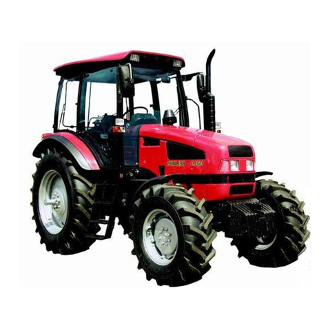
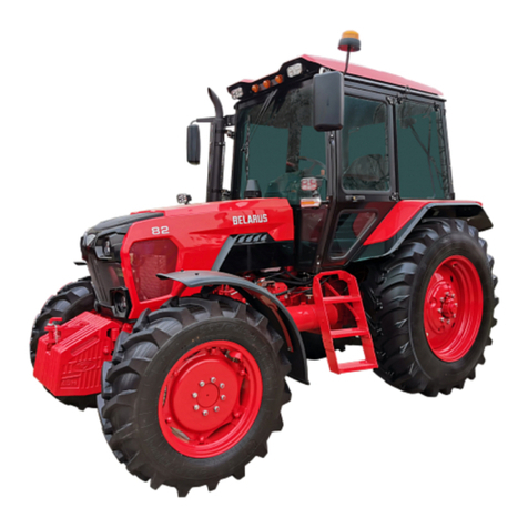
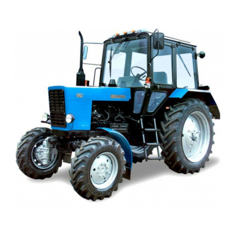
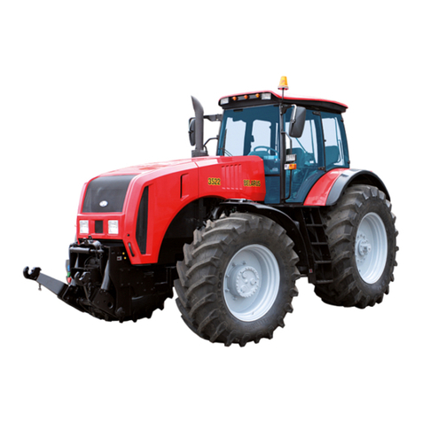
Belarus 80.1 Series User manual

BELARUS
80.1/82.1/820
80-0000010B OM
OPERATION MANUAL
2015

The operation manual was composed by an engineer of the first Department of
Constructive and Experimental Works (DCEW-1), Y.A. Soroka, with participation of key
specialists of DCEW-1 of OJSC “Minsk Tractor Works”
Publication responsible person – Y.M. Korotky, head of engineering office of design
documentation of the DCEW-1.
Executive editor – Zezetko N.I., head of DCEW-1.
Editor-in-chief – Stasilevitch A. G., chief designer of tractor production of OJSC
“MTW”.
Operation manual contains brief description and specifications of tractors “BELA-
RUS-80.1/82.1/820” produced by Minsk Tractor Works. The main tractors operating rules
are set forth, the information about their adjustments and maintenance is provided.
Operation manual is meant for tractor study, operation rules and maintenance of
tractors “BELARUS-80.1/82.1/820”.
In view of Minsk Tractor Works policy directed to constant upgrading of produced
goods, the construction of some units and parts of Belarus tractor may undergo changes
which are not reflected in present edition. The detailed information may be obtained from
“BELARUS” dealer.
© OJSC ”Minsk Tractor Works”, 2015
All rights reserved. No part of this book may be reproduced in any form without writ-
ten permission of OJSC “MTW”.

80-0000010B OM
3
CONTENTS
1 TRACTOR DESCRIPTION AND OPERATION………………………………………….. 13
1.1
A
ssignment of tractor……………………………………………………………………… 13
1.2 Technical specifications …………………………………………………………………. 17
1.3 Tractor composition……………………………………………………………………….. 21
1.4 Vibration level at the operator's working place of the tractor ……..……………………..... 23
1.5 Marking of the tractor……………………………………………………………………… 23
1.6 Packing….………………………………………………………………………………….. 23
2 CONTROLS AND INSTRUMENTS………………………………………………………... 24
2.1 Layout of controls and instruments of the tractor ……………..………………………. 24
2.2 Switches of the instrument board…………………….…………………………………. 26
2.3 Uppe
r
dashboard unit of button switches and rear window wiper switch….……….. 28
2.4 Cab heater and fan control ………………………….…………………………………… 29
2.5 Instrument board…………………………………………….…………………………….. 31
2.6 Pilot lamps unit ……………………………………………………………………………. 33
2.7 Tachospeedometer….…………………………………………………………..………… 34
2.7.1 General information……………………………………………………………………... 34
2.7.2 Tachospeedometer
А
Р70.3813………..………………………………………………… 34
2.7.3 Multifunctional indicator unit КД 8083………..………………..……………………… 35
2.8 Steering……………….……………………………………………………………………. 36
2.8.1 General information………………………………………………………………..……. 36
2.8.2 Steering wheel adjustments…..………………………………….……………………. 36
2.9 Parking brake control…………………………………………………………………....... 37
2.10 Engine stop handle, accumulator batteries switch…………………………...………. 37
2.11Handle fo
r
fuel supply manual control, shutte
r
control of engine cooling system…. 37
2.12 Tracto
r
pedals and rear axle differential lock control…………………………..…….. 37
2.13 Shifting of gears...…………………………………………………………………………...... 39
2.13.1 General information………………………………….……………………………….. 39
2.13.2 Gea
r
shifting in transmission with mechanical gearbox and mechanical o
r
syn-
chronized gear reduction unit …………………………………………………………………39
2.13.3 Gear shifting in transmission with mechanical gearbox and reverse-reduction
gear……….….………………………………………………………………………………….. 41
2.14 Front driving axle drive control on tractors “BELARUS-82.1/820”………………….. 43
2.15 Powe
r
take-off shafts control……………. …………………………....……………….. 44
2.15.1 General information……………………………………………………………………. 44
2.15.2 Rear power take-off shaft control………………..……….………………………….. 44
2.15.3 Side semi-continuous powe
r
take-off shaft control……………………..…...…….. 45
2.16 Hydraulic lift linkage control……………...………………….………………………..... 46
2.16.1 General information...……………………………..………………..…………………. 46
2.16.2 HLL pump control…………....………………………...……………………………….46
2.16.3 Remote hydraulic cylinders control………… …….....………………………..…..... 47
2.16.4 Control of RLL locking mechanism in transport position on tractors without draft
control …………………………………....…………………………………………….…........ 51
2.16.5 Control of RLL locking mechanism in transport position on tractors with draft
control …………………………………………………………………………………………... 51
2.16.6
A
djustable implement lift kickout ……………….……………………………………. 51
2.17 Control elements of RLL and hydraulic hook grips o
r
lowering link with draft con-
trol …………………………………………………………………………….………………… 52
2.17.1 Rear lift linkage control………………………………………………………………... 52
2.17.2 Hydraulic hook grips or lowering link control……………………………………...... 55
2.18 Electrical cut-out fuses and relays………………….....……………………………….. 56
2.18.1 General information……………………………………………………………………. 56
2.18.2 Fuses of instrument dashboard with cast panel …………………………………… 56

80-0000010B OM
4
2.18.3 Fuses of the instrument dashboard with molded panel ………..………………..... 57
2.18.4 Fuses located on the HLL and HSC (HLL) oil tank body …………………………. 59
2.18.5 Electro-magnetic relays ………………………………………………………………. 59
2.19 Cab locks and handles..………………………………………………………………… 62
2.19.1 Cab door locks...……………………………………………………………………….. 62
2.19.2 Side window opening………………………………………………………………….. 62
2.19.3 Rear window opening…………………………………………………………………. 63
2.19.4 Cab roof opening………………………………………………………………………. 63
2.20 Seat and its adjustments…………………………………………………………………64
2.20.1 General information……………………..………………………………………..…… 64
2.20.2
A
djustments of seat “BELARUS”…..….………………………..……………..…….. 64
2.20.3
A
djustments of seat “Gramme
r
”…………………..………………………………….. 65
2.21 Pneumatic system compressor control ……..……………..…………………............ 66
2.22 Connector elements of the electrical equipment ……………………..……………… 66
2.22.1 Socket to connect electrical equipment of coupled agricultural machines………. 66
2.22.2 Connection of additional electrical equipment of coupled machines…………........ 67
2.23 Fuel tank valves control…………………..………………………..…………….……… 68
2.24 Layout of instruments and controls of tractor with molded panel of instrument
dash-board ……………………………………………………………………………...………69
2.25 Pilot lamps unit of tractors with dashboard with molded panel …………………….. 71
2.26 Multifunctional indicator unit of t
r
actors with dashboard with molded panel ……… 72
2.26.1 General information……………………………………………………………………. 72
2.26.2 Operation principle and assignmen
t
of indicators of multifunctional indicato
r
uni
t
…... 72
2.26.3 Pilot lamps of multifunctional indicato
r
unit....…………..………………………….. 74
2.26.4 Description of instrument operation check……………..…………………………… 74
2.27 Creeper control…………………….…………………………………………………….. 75
2.28 Distinctive features instruments and controls of tractors BELARUS-80.1/82.1 with cano-
py-frame or canopy base on the basis of small cabin………………………………..………….. 76
2.28.1 Layout of instruments and controls of tractors with canopy frame or canopy
base on the basis of small cabin……………………………………………………………... 76
2.28.2 Switches and selectors of instrument board of tractors with canopy frame or
canopy base on the basis of small cabin …………………………………………………… 77
2.28.3 Gauges and tachospeedometer of tractors with canopy frame or canopy base
on the basis of a small cabin ……………………..………….………………………………. 77
2.28.4 Warning and pilot lamps of tractors with canopy frame or canopy base on the
basis of small cabin …………………………………………………………………………… 79
2.28.5 Steering of tractors with canopy-frame o
r
canopy base on the basis of small
cabin................................................................................................................................ 80
2.28.6 FD
A
drive control of tractors BELARUS-82.1 with canopy frame o
r
canopy
base on the basis of small cabin………………..……………………………………………. 81
2.28.7 Rea
r
powe
r
take-off shaft disengagement of tractors with canopy frame o
r
can-
opy base on the basis of small cabin……..…………………………………………………. 82
2.28.8 Control of RLL locking mechanism in transport position on tractors BELARUS
80.1/82.1 with canopy frame or canopy base on the basis of small cabin………………. 82
2.28.9 Operation of rear lift linkage with draft control of tractors with canopy frame or
canopy base on the basis of a small cabin ……………………………….………………… 83
2.28.10 Fuses of dashboard of tractors with canopy frame o
r
canopy base on the ba-
sis of small cabin………………………………………………………………………………..86
2.28.11 Electro-magnetic relays……………………………………………………………… 87
2.28.12 Seat and its adjustment on tractors BELARUS-80.1/82.1 with canopy frame
or canopy base on the basis of small cabin………………...……………………………….88
3 DESCRIPTION AND OPERATION OF TRACTOR COMPONENTS ………....………. 89
3.1 Engine and its systems…..………………………..…………………………..…………..89
3.1.1 Engine………...………………..………………………………………………..……….. 89

80-0000010B OM
5
3.1.1.1 General information…………………………………………………………..………. 89
3.1.1.2 Engine components………….……………………………………………………….. 90
3.1.2 Engine air cleaning system……………………………………..……………………… 94
3.1.3 External part of engine cooling system…………..……………………………………95
3.2 Clutch……..…………………………..………………………………………….………….96
3.2.1 Clutch coupling…..………………………………..…………………………….………. 96
3.2.2 Peculiarities of clutch coupling dismounting, mounting and adjustmen
t
…...…..…… 97
3.2.2.1 General information………………………..……………………………………..….... 97
3.2.2.2 Dismounting of clutch coupling …………………………..…………………………. 98
3.2.2.3 Mounting of clutch coupling…..……………………..…………………………….....98
3.2.2.4
A
djustmen
t
of clutch coupling release levers…………..……………..…………...... 98
3.2.3 Clutch control……………..…………………………………...………………………… 99
3.2.3.1 General information………………………………………………….……………….. 99
3.2.3.2
A
djustment of clutch coupling pedal free travel……………...….…….….……….. 99
3.2.4 Clutch casing ………………..……….………………...………………………….……. 100
3.3 Gearbox………….…………..……………………………………………………….…..... 104
3.3.1 General information….…………..……………………………………………….…….. 104
3.3.2 Gearbox with gears and ranges shifting leve
r
located at the right hand of the op-
erator………………...………………………………………………………………………….. 104
3.3.2.1Gearbox mechanical gea
r
unit…..……………….…………...……………………… 104
3.3.2.2 Gearbox control ……………………………...……………….…..............................109
3.3.2.3 Gearbox operation….…………….………………………….……………………….. 110
3.3.3 Distinctive features of design and operation of mechanical gearbox with gears
and ranges shifting lever located in the center……………………………………….…….. 112
3.3.4 Reverse-reduction gear…..…………………………………………………………….. 114
3.3.4.1 General information…………………………………………………………………… 114
3.3.4.2 Composition of reverse-reduction gear …………………………………………….114
3.3.4.3 Mechanical gear unit………….………………………………………………………. 115
3.3.4.4 Reverse-reduction gear control……………………………………………………… 115
3.3.4.5 Reverse-reduction gear operation………………………………………………......115
3.4 Rear axle………...……………………………………………………………………….....116
3.4.1 General information……………………………………………………………………... 116
3.4.2 Main gear………………………………………………………………………………… 116
3.4.3 Differential……..…………………………………………………………………………. 117
3.4.4 Final drives………………………………………………………………………………. 117
3.4.5 Rear axle differential lock……………………….……………………………………… 118
3.4.5.1 Differential lock coupling……………….…………………………………………….. 118
3.4.5.2 Rear axle differential lock control with the help of the pedal………………….………. 119
3.4.5.3 Cable control of rear axle differential loc
k
………………………………….…………... 120
3.4.5.4 Rea
r
axle differential lock cable control adjustment ………………...……………. 121
3.5 Rear power take-off shaft ………………..……………………………………………..... 122
3.5.1 General information…………………………………………..…………………………. 122
3.5.2
A
djustment of play in power take-off shaft strap brakes…………………………….122
3.5.3 External adjustment of brake straps………..……..………………………………….. 124
3.5.4 Rear PTO control………….………………………………………..…………………… 124
3.5.5 Rea
r
PTO control on tractors with canopy-frame o
r
canopy base on the basis o
f
small cabin…………………...……………………………………………………………….... 125
3.6 Side semi-continuous power take-off shaft………..……………………………………. 126
3.7 Brakes………………………………………………………………………………………. 127
3.7.1 Service brakes and service brakes control……………………………………………127
3.7.2 Check/adjustment of service brakes control…………………..……………………... 128
3.7.3 Parking brake………..……………………………..….….…..….………………………129
3.7.4
A
djustment of parking brake control …..……………...…………….……..…...…..... 130

80-0000010B OM
6
3.8 Pneumatic system……………………………………………………………………........ 132
3.8.1 General information…………………………………………………………………...... 132
3.8.2 Single-line pneumatic drive………………………………………………..……….….. 132
3.8.2.1 Operation of single-line pneumatic drive…..…………………………………..…… 132
3.8.2.2 Check and adjustment of pneumatic system brake valve drive……...…............. 133
3.8.3 Check and adjustment of pneumatic system pressure regulator…..……..……….. 135
3.9 3.9 Front axle 80-3000030 of tractor “BELARUS-80.1”……………………………….. 136
3.10 Front driving axle………………………………………………………………………….137
3.10.1 FDA with bevel wheel gea
r
group……………………………………………………. 137
3.10.1.1 General information….……………………………………………………………… 137
3.10.1.2 FDA differential………………………………………………………………………. 138
3.10.1.3 Bevel wheel gea
r
group......……………………………………………….............. 139
3.10.1.4
A
djustment of FD
A
with bevel wheel gea
r
groups……….…...…………………. 141
3.10.2 FDA with planetary spu
r
wheel gea
r
groups……………….……………................ 143
3.10.2.1 General information…………………………………………………………………. 143
3.10.2.2 Wheel gea
r
group of planetary spu
r
type………….……………………………… 144
3.10.2.3
A
djustments of FD
A
with planetary spu
r
wheel gea
r
groups ......……………… 146
3.10.3 FDA drive………..……………………………………………………………………… 149
3.10.3.1 Cardan drive………..…………………………………………………………………149
3.10.3.2 Transfer box …………………………………………………………………………. 150
3.10.3.2.1 General information.………………………………………………………………. 150
3.10.3.2.2 Transfe
r
gearbox control on tractors BELARUS-82.1/820 with universal
cabin (canopy frame or canopy base on the basis of universal cabin)…………………... 151
3.10.3.2.3 Transfe
r
gearbox control on tractors BELARUS-82.1 with canopy frame o
r
canopy base on the basis of small cabin…………..……………..…………………………. 152
3.10.3.3
A
djustment of the control link of the FDA drive transfer box…………..……...... 154
3.10.3.4
A
djustment of control link of the FDA drive transfer box on tractors “BELA-
RUS-82.1” with canopy frame or canopy base on the basis of a small cabin ………...... 154
3.10.3.5
A
djustment of FD
A
cardan drive…………………………………………………… 154
3.11 Tractor undercarriage………….………………………………………………………… 155
3.12 Hydrostatic steering control……………..………………………………………...….....157
3.12.1 General information.…………………………………………………………………… 157
3.12.2 Dosing pump………………………………………………………………………….... 161
3.12.3 Hydraulic cylinder of steering…………..…………………………………………….. 162
3.12.4
A
larm of HSC hydraulic system emergency state………………………………….. 162
3.13 Hydraulic power stee
r
ing……..…………………………………………………………. 163
3.13.1 General information..………………………………………………………………….. 163
3.13.2
A
djustments of hydraulic power stee
r
ing……………...……………...…………….. 165
3.13.3 Installation of distributor on hydraulic power steering housing…..……………….. 166
3.14 Hydrostatic steering control with hydraulic powe
r
steering housing………………... 167
3.14.1 General information.…………………………………………………………………... 167
3.14.2
A
djustment of axial stroke of turning shaft ……...………………………………….. 168
3.15 Hydraulic lift linkage…………………………………...………………………………… 169
3.15.1 General information……………………………………………………………………. 169
3.15.2
A
djustment of draft (position) control …………………………………………......... 177
3.15.2.1
A
djustment of draft control operating link………………...………………………. 177
3.15.2.2
A
djustment of draft sensor………………………………………………………….. 177
3.15.2.3
A
djustment of position link………………………………………………………….. 177
3.15.2.4
A
djustment of draft link…..…………………………………………………………..178
3.15.2.5
A
djustment of draft control operating link on tractors with canopy frame o
r
canopy base on the basis of small cabin…………………...……………………………….. 179
3.16 Rea
r
lift linkage…………………………………………………………………………… 180
3.16.1 General information………………..………………………………………………….. 180
3.16.2 Rules of RLL elements control…………..…………………………………………… 181

80-0000010B OM
7
3.16.2.1 Buckles...……….…….………………………………………………………………. 181
3.16.2.1.1 General information……………….………………………………………………. 181
3.16.2.1.2 Telescopic buckles ……………………………………………………………….. 181
3.16.2.1.3 External turnbuckles………………………………………………………………. 183
3.16.2.1.4 Internal buckles……….…………………………………………………………… 184
3.16.2.2 Lifting rod….………………………………………………………………………….. 185
3.16.2.3 Upper link……..…………………………………………………………………….... 186
3.16.2.4 Lower links…….………………………………………………………………………187
3.16.2.4.1 General information……………………………………………………………….. 187
3.16.2.4.2 Installation in working position of crossba
r
and rea
r
ends of detachable
lower links ………………………….…………………………………………………………... 187
3.16.2.4.3 Telescopic lowe
r
links and double cross bar……………..……………………. 188
3.16.3 Mounting of implements on a tractor..………………………………………………..189
3.17 Tow hitches…..…………………………………….…………………………………….. 190
3.17.1 General information……………………………………………………………………. 190
3.17.2 Tow hitch TSU-2 (hydraulic hook) and combined device TSU-2M-02 (with hy-
draulic hook set in the working position and pendulum, set in the additional position)… 191
3.17.3 Combined device ТSU-1М-02 (combined device with pendulum set in the wo
r
k-
ing position hydraulic hook set in the additional position)…...…………………………….. 192
3.17.4 Tow hitch TSU-1M (pendulum)……………………………………………………..... 192
3.17.5 Lowering link……….…………………………………………………………………... 192
3.17.6 Basic parameters and coupling dimensions of TSU-1M-02 (combined device
with pendulum in working position), TSU-1M (pendulum) and of lowering link ………… 193
3.17.7 Tow hitch TSU-1Zh (cross ba
r
)………………………………………………………. 194
3.17.8 Tow hitch TSU-1Zh-01 (double cross ba
r
)………………………………………….. 194
3.17.9 Resetting of pendulum and hydraulic hook in a combined device…………..…… 195
3.17.10 Tow hitch TSU-2 (autonomous hydraulic hook)…………………………………... 199
3.18 Electrical equipment…..…………………………………………………………………. 200
3.18.1 General information………………………………………………………………….... 200
3.18.2 Operation principle of heating plugs pilot indicato
r
-lamp ..................................... 200
3.18.3 Programming procedure fo
r
tachospeedomete
r
of instrument board with cast
panel…………………………………………………………………………………………….. 201
3.18.3.1 Tachospeedometer control panel………..……………….……………….………. 201
3.18.3.2 Programming orde
r
of electric tachospeedomete
r
A
P70 3813……………………… 201
3.18.3.3 Programming procedure for integrated indicator unit КД8083…………...…….. 202
3.18.4 Programming procedure fo
r
tachospeedomete
r
of instrument board with mold-
ed panel……........………………………………………..………………...…………...……... 204
3.18.4.1 Tachospeedomete
r
control panel………………….…………………………….... 204
3.18.4.2 Tachospeedometer programming procedure ...………………………………….. 204
3.18.5 Installation and adjustment of speed sensors………………………………………. 206
3.19 Cabin...…………………………………………………………………..…………….......207
3.19.1 General information…………………….……………………………………………… 207
3.19.2 Mounting and dismounting of complete cabin………..………..…………………… 207
3.19.3 External mirrors……………………………………………………………..…………. 208
3.19.4 Mounting and dismounting of canopy frame (canopy base) on the basis of uni-
versal cabin…………………………………....................................................................... 208
3.19.5 Mounting of canopy on the base (on the basis of universal cabin)………….…… 209
3.19.6 Mounting and dismounting of canopy frame (canopy base) on the basis o
f
small cabin……………………………………………………………………………………… 210
3.19.7 Mounting of canopy on the base (on the basis of a small cabin) ……………….. 211
3.20 Front wheel fenders with turning mechanism……………………………..………….. 212
3.20.1 General information………………………………………………………………….... 212
3.20.2
A
djustment of front wheel fenders with turning mechanism ………. ……………. 212
3.21 Markin
g
of tractor components…………….…………………………………………… 213

80-0000010B OM
8
4 INTENDED USE OF TRACTOR ………………………..……………………………........ 215
4.1 Safet
y
measures while preparin
g
tractor for operation…..…………………………… 215
4.2 Tractor use …………………..…………………………………………………………….. 216
4.2.1 Boardin
g
the tractor...………………………………………………………………....... 216
4.2.2 Preparin
g
for en
g
ine start and startin
g
the en
g
ine …………………...……..……… 216
4.2.2.1 General instructions…………………………………………………………………... 216
4.2.2.2 Preparin
g
for en
g
ine start and startin
g
the en
g
ine………………………………........ 216
4.2.2.2.1 Preparing for engine start and starting the engine on tractors with universal
cabin
(
canop
y
frame or canop
y
base on the basis of universal cabin
)
…………………... 216
4.2.2.2.2 Preparing for engine start and starting the engine on tractors with canopy
frame or canop
y
base on the basis of small cabin ………………………………………… 218
4.2.3 Start of tractor movement, GB shiftin
g
…………...……………………...……..…….. 219
4.2.4 Tractor stop…………………………………………………………………..………….. 221
4.2.5 En
g
ine stop……………..……………………………………………………..………… 221
4.2.6 Leavin
g
the tractor…..…………………………………………………………..……….221
4.2.7 PTO use……………...……………………………………………………………..……. 222
4.2.8 Selecting of optimal inner pressure in tyres depending on operational conditions
and load on tractor axles, instructions for use of t
y
res………………….……..…………... 224
4.2.8.1 Selection of optimal inner pressure in tyres depending on operational condi-
tions and load on tractor axles…………………………………………………..…………… 224
4.2.8.2 Instructions for use of t
y
res……………………………..…………………………….226
4.2.8.3 T
y
re inflation……..………………………………………………..………………....... 227
4.2.9 Rear wheel trac
k
formation………….……………………..………..…………………. 229
4.2.9.1 Track formation for rear wheels mounted on terminal hubs.…………………….. 229
4.2.9.2 Track formation for rear wheels mounted on bevel hubs………..………………. 230
4.2.10 Rear wheel twinnin
g
……….………………………………………………………….. 231
4.2.11 Front wheel track formation……………..…………………………………………..... 232
4.2.11.1 General information…………………………………………………………………. 232
4.2.11.2 Front wheel track formation of tractors, equipped with non-drivin
g
front axle .. 232
4.2.11.3 Front wheel track formation of tractors, equipped with FDA with bevel wheel
g
ear
g
roups……………………..……………………………………………………………….236
4.2.11.4 Front wheel track formation of tractors, equipped with FDA with planetary
spur wheel
g
ea
r
g
roups…………………………………………….…………………………. 239
4.3 Safet
y
measures durin
g
tractor ope
r
ation…..………………..……..………………….. 242
4.3.1 General safet
y
measures durin
g
tractor operation …..…………………..…………. 242
4.3.2 Fire safet
y
measures …………………….……………………..……………………… 245
4.4 Tractor final assembl
y
and run-in…………………………….………………………….. 246
4.4.1 Tractor final assembl
y
………………………..…………………………………………. 246
4.4.2 Technical maintenance before tractor run-in……………….………………………... 246
4.4.3 Tractor run-in…………………………………………..………………………………... 246
4.4.4 Technical maintenance durin
g
tractor run-in………………….……………..………. 247
4.4.5 Technical maintenance after tractor run-in……………...…………..……………...... 247
4.5 Emer
g
enc
y
actions………………………………………..………………………………. 248
5 COUPLING OF IMPLEMENTS…...………..……………………………………………….249
5.1 General information….…………………………………..……………………………...... 249
5.2 T
y
pes of a
g
ricultural implements coupled with tractors…………………………..…… 250
5.3 Three-point rear lift linka
g
e …………………….………………………………………… 252
5.4. Peculiarities of tractor hydraulic system use for driving of operated parts and oth-
er elements of unitized h
y
draulicall
y
operated machines and a
ggr
e
g
ates…………..….. 255
5.5 Use of safet
y
clutches when PTO and cardan shaf
t
are applied……......…………..……….257
5.6 Peculiarities of use of PTO and cardan shafts …………..……….…………….……… 258
5.7 Ways of changing tractor grip characteristics and passability ………………..……… 261
5.7.1 General information …………………………….………..…………………………….. 261
5.7.2 Ways of changing tractor grip characteristics and passability………………........... 262
5.7.3 Use of mounted quick-detachable ballast……………..…………….……..……....... 262
5.7.4 Pouring water (solution) into the tyres of the rear wheels to increase grip……….. 262
5.7.5 Procedure of filling tyres with water or aqueous solution......……………..………... 263

80-0000010B OM
9
5.7.6 Procedure of partial release of water or aqueous solution from tyres ……………. 264
5.7.7 Procedure of complete release of wate
r
o
r
aqueous solution from tyres ………… 264
5.7.8 Selection of inner tyre pressure………..…………………………………..……......... 264
5.7.9
A
pplication of rear axle differential lock………………………..………..……………. 265
5.8 Peculiarities of tracto
r
application in special conditions……………………..………… 266
5.8.1 Tracto
r
operation in areas with rugged topography. Possibility of using the trac-
to
r
for ha
y
la
g
e preparation ……………………………….……………..……..…………..... 266
5.8.2
A
pplication of substances for chemical treatment…..……………….…..………….. 266
5.8.3 Operation in a forest……..…………………….……...………………………….......... 266
5.9 Determination of total weight, loads on front and rear axles, tyres holding capacity
and the required minimum ballast………………………………..………….……................ 267
5.10 Possibility of front loade
r
installation…………………..……………………………..... 269
5.10.1 General information….………………………………………………………………… 269
5.10.2 Safety measures to be taken when operating tractors BELARUS-80.1/82.1/820
with loader installed……………………………………………………………………………. 271
5.10.3 Information on the tractor mounting holes…………………………………………... 273
6 TECHNICAL MAINTENANCE…………..……………………………..……………………275
6.1 General instructions………………………………………………………………..……… 275
6.2 Providing access to tracto
r
components fo
r
technical maintenance……..…............. 277
6.3 Technical maintenance procedure…………………….………………………………… 283
6.4 Scheduled technical maintenance operations………….………………………………. 286
6.4.1 Technical maintenance on a shift basis every 8-10 hours of operation o
r
every
shift…………………………………….…………………………….…………………….……. 286
6.4.2 Technical maintenance every 125 hours of ope
r
ation……………….……………… 290
6.4.3 Technical maintenance every 250 hours of operation…………………….…........... 296
6.4.4 Technical maintenance every 500 hours of operation……………….………........... 307
6.4.5 Technical maintenance every 1000 hours of operation ………….…...................... 316
6.4.6 Technical maintenance every 2000 hours of operation …….………...................... 335
6.4.7 General technical maintenance ……..……………………………………..…………. 338
6.5 Seasonal technical maintenance ………………………………………..……………… 340
6.6 Safety measures during TM and repair operations....… ………….……….…………. 340
6.6.1 General safety measures………….……………..…………………………………….. 340
6.6.2 Safety precautions for exclusion of hazardous situations related to accumulator
batteries and fuel tank …………………………………………..……………………………. 340
6.7 Filling and lubrication of the tractor with fuel and lubrication materials …….………. 343
7. POSSIBLE FAILURES AND INSTRUCTIONS FOR TROUBLESHOOTING………... 349
7.1 Possible failures of the engine and instructions for troubleshooting……...…………. 349
7.2 Possible failures of the clutch and instructions for troubleshooting ..…..……………. 352
7.3 Possible failures of the gearbox and instructions fo
r
troubleshooting ………………. 353
7.4 Possible failures of the rear axle and instructions for troubleshooting ……………… 353
7.5 Possible failures of the rear power take-off shaft and instructions for troubleshoot-
ing………………………………………………………………………………….....................354
7.6 Possible failures of the brakes and instructions for troubleshooting ………………… 355
7.7 Possible failures of the pneumatic system and instructions for troubleshooting…… 356
7.8 Possible failures of the front driving axle…………………...…………………………... 358
7.9 Possible failures of the hydrostatic steering control and instructions for trouble-
shooting…………………………..……………………………………………………………...360
7.10 Possible failures of the hydraulic power steering and instructions for trouble-
shooting………………………………………………..……………………………………….. 363
7.11 Possible failures of the hydrostatic steering control with HPS housing and in-
structions for troubleshooting ……..…………………………………………………………. 364
7.12 Possible failures of the hydraulic lift linkage and instructions fo
r
thei
r
troubleshoot-
ing………………….……….…………………………………..…..…………………………… 366
7.1
3
Possible failures of the electrical equipment and instructions for troubleshooting… 368

80-0000010B OM
10
7.14 Possible failures of the ai
r
ventilation and cab heating system and instructions fo
r
troubleshooting …………….…………………………………..…..………………………….. 370
8. TRACTOR STOR
A
GE…………………………..…………………………………………. 371
8.1 General instructions…………………………………….…………………………………. 371
8.2 Requirements for inte
r
-shift storage of tractors..……………………….……………… 371
8.3 Requirements for short-term tractor storage………………..………………………….. 371
8.4 Requi
r
ements for outdoors long-term storage ………………….…..…………………. 371
8.5 Preservation..…………..………………………………………………………………….. 373
8.6 Depreservation and represervation…...…………………………….………………....... 373
8.7 Putting tractor into operation after long-term storage …………………..…................ 373
8.8 Safety requirements for preservation…………..………………..…………………….... 374
9. TRACTOR TRANSPORTATION AND TOWING ………..…………............................. 375
9.1 Tractor transportation……………………………………………………………………... 375
9.2 Tractor towing…………………………………………………………………………....... 376
10. Tractor disposal ………………………..…………………………………....................... 377
Service bulletins ………………………..……………………………………………………… 378
A
NNE
X
А
(compulsor
y
)
–
Electric circui
t
diagram of tractors “BEL
A
RUS
–
80.1/82.1/820”
electrical equipment connections (dashboard with cast panel)……………………………… 379
A
NNEX B (compulsory)
–
Electric circui
t
diagram of tractors “BEL
A
RUS
–
80.1/82.1/820”
electrical equipment connections (dashboard with molded panel)…...…………………..…. 380
A
NNE
X
C (compulsor
y
)
–
Electric circui
t
diagram of tractors “BELARUS
–
80.1/82.1” elec-
trical equipment connections with tent frame or tent base on the basis of small cabin……. 381

80-0000010B OM
11
Introduction
The present manual is intended for studying the structure, operation rules and maintenance of
tractors “BELARUS-80.1/82.1/820”.
Scrutinize this manual. It will help you to study the rules of correct operation and
maintenance.
Failure to follow this instruction can lead to operator's injury or a breakdown of a tractor
or to inflicting damage to the third persons.
Operation of tractor, its maintenance and repair shall be carried out only by employees,
familiar with all of its parameters and characteristics and informed about necessary safety re-
quirements to prevent casualties.
In connection with constant development of tractor some changes, which are not de-
picted in the present manual, can be introduced in the structure of certain units and parts.
Any arbitrary changes made by a consumer release the manufacturer from responsibil-
ity for possible further injuries to the operator and tractor breakdown.
Adopted abbreviations and conventional notations:
AB – accumulator battery;
DL – differential lock;
PLU – pilot lamps unit;
FB – fuse block;
PTO – power take-off shaft;
PRS – power reception shaft;
HSC – hydrostatic steering control;
HPS – hydraulic power steering;
HLL – hydraulic lift linkage;
HS – hydraulic system;
STM – shift-time maintenance;
LCI – liquid crystal indicator;
SPTA – spare parts, tools and accessories;
RA – rear axle;
RLL – rear lift linkage;
GB – gearbox;
SC – small cabin;
CC – coupling clutch;
MTU – machine and tractor unit;
LL – lift linkage;
CL – cooling liquid;
CP – control panel;
FDA – front driving axle;
HPH – high pressure hoses;
HP – heating plugs;
SM – seasonal maintenance;
TM – technical maintenance;
TM1 – technical maintenance No1;
TM2 – technical maintenance No2;
TM3 – technical maintenance No3;
TH – tow hitch;
UC – universal cabin;
EE – electrical equipment;

80-0000010B OM
12
The manufacturer uses standard international symbols, regarding application of instru-
ments and control units. Given below are the symbols with indication of their meanings.
— see the manual; — control manipulations;
— brake; — fast;
— manual brake;
— slowly;
— audible beep; — forward;
— alarm signaling;
— reverse;
— fuel;
— accumulator charging;
— coolant;
— cab roof light;
— heating plugs;
— parking lights;
— engine speed;
— tractor turn indicator;
— oil pressure in the engine;
— trailer turn indicator;
— temperature of engine cool-
ant;
— upper beam;
— air filter clogged;
— low beam;
— off / stop;
— working lights;
— on / start; — differential lock;
— gradual adjustment; — PTO engaged;
— rear screen wiper; — engine stop;
— front screen wiper and
washer;
— fan;
— oil pressure in HSC; — engine start;
— air pressure in pneumatic
system; — external cylinder – retracting;
— swivel lever – up;
— external cylinder - protracting;
— swivel lever – down; — external cylinder – floating;

80-0000010B OM
13
1 Tractor description and operation
1.1 Assignment of tractor
Tractors “BELARUS- 80.1/82.1/820” are intended for performance of various gen-
eral–purpose agricultural operations with mounted, semi-mounted and trailed machines
and implements, for loading-unloading works and transportation works in plant growing
and cattle breeding.
Main distinctive features of tractor models are indicated in table 1.1.1.
Table 1.1.1
Tractor model
Engine model;
Engine rated
power, kW
Undercarriage Distinctive features
“BELARUS-80.1” Д-243; 59,6
(Д-243С; 60,0) 4X2 Front axle
“BELARUS-82.1” Д-243; 59,6
(Д-243С; 60,0) 4X4 FDA 72
“BELARUS-820” Д-243; 59,6
(Д-243С; 60,0) 4X4 FDA 822, updated design
Appearance of standard configuration of tractor “BELARUS-80.1” is presented in
figure 1.1.1.
Appearance of standard configuration of tractor “BELARUS-82.1” is presented in
figure 1.1.2.
Appearance of standard configuration of tractor “BELARUS-820” is presented in fig-
ure 1.1.3.
Appearance of tractors “BELARUS-80.1/82.1/820” complete with canopy base and
canopy frame on the basis of a universal cabin is shown in figure 1.1.4.
Appearance of tractors “BELARUS-80.1/82.1” complete with canopy base and can-
opy frame on the basis of a small cabin is shown in figure 1.1.5.

80-0000010B OM
14
Figure 1.1.1 – Tractor “BELRUS-80.1”
Figure 1.1.2 – Tractor “BELARUS-82.1” (the rest is in figure 1.1.1)

80-0000010B OM
15
Figure 1.1.3 – Tractor “BELARUS-820”

80-0000010B OM
16
а) canopy base b) canopy frame
Figure 1.1.4 – Tractors “BELARUS-80.1/82.1/820” with canopy base and canopy
frame on the basis of a universal cabin (the rest is in figure 1.1.1 for “BELARUS-80.1”, in
figure 1.1.2 for “BELARUS-82.1” and in figure 1.1.4 for “BELARUS-820”)
а) canopy base b) canopy frame
Figure 1.1.5 – Tractors “BELARUS-80.1/82.1” with canopy base and canopy frame
on the basis of a small cabin (the rest is in figure 1.1.1 for “BELARUS-80.1” and figure
1.1.2 for “BELARUS-82.1”)

80-0000010B OM
17
1.2 Technical specifications
Basic parameters and technical specifications of the tractors “BELARUS-
80.1/82.1/820” are given in table 1.2.1.
Table 1.2.1
Parameter
(characteristics) title
Parameter value for tractor
80.1 82.1 820
1 Traction class as per GOST
27021:
1,4
2 Rated traction force, kN: 14
3 Engine 1):
а) model: Д-243
(Д-243С)
b) engine type 2): Without turbocharging
c) number and position of cylin-
ders 2):
Four, in-line, vertical
d) displacement, l 2
)
: 4,75
e) engine power, kW:
1) rated 2): 59,6 (60,0)
2) operational with supple-
mentary equipment:
57,4+3,7
(57,8±1,0)
f) crankshaft rated speed, min
-
1 2):
2200
g) specific fuel consumption at
operational power, g/(kWꞏh) 2):
235
(244)
permissible deviation, %: +3,0(+5,0)
h) turning torque backup rated
factor, % 2):
15
(15)
i) maximum turning torque, Nꞏm
2):
298
(298)
j) permissible longitudinal and
lateral tilt of running engine, not
more:
20°
k) specific burning oil consump-
tion not more:
0,9+0,4
(0,9+0,4)
l) minimum stable idle speed,
min-1:
800
m) speed at maximum turning
torque value, min-1, not less:
1600
(1400)
4 Rear PTO power: In subsection 4.2.7 “PTO use”
5 Specific fuel consumption at
rear PTO power in the PTO mode
“540 rpm”, g/(kWꞏh), not more:
255
6 Number of gears:
а) for forward travel 183)
b) for backward travel 43)

80-0000010B OM
18
Table 1.2.1 continued
Parameter
(characteristics) title
Parameter value for tractor
80.1 82.1 820
7 Tractor travel speed (calculat-
ed) at rated engine crankshaft
speed, on tyres of basic configu-
ration, km/h:
а) for forward motion:
1) least: 1,94 1,94 2,09
2) highest: 34,3 34,3 36,9
b) for backward motion:
1) least: 4,09 4,09 4,40
2) highest: 9,22 9,22 9,9
8 Tractor weight, kg:
а) structural: 3520±100 3750±100 3850±100
b) operating with ballast:
3770±100
4000±100
4100±100
c) maximum operating:
6300
6500
6500
d) in the condition of loading ex-
works: 4)
3620
3850
3950
9 Distribution of operational
weight on axles 5), kg:
а) on front axle: 1130 1340 1440
b) on rear axle: 2640 2660 2660
10 Permissible load on axles, kN:
а) on front axle: 17,5 24,0 37,0
b) on rear axle: 50,0 50,0 50,0
11 Max. weight of towed trailer
(trailer brakes are interlocked with
tractor brakes), kg:
9000
12 Agrotechnical clearance under
rear wheel assemblies (on tyres
of basic configuration), mm, not
less, than:
645±10
645±10
510±10
13 Track dimensions (on tyres of
basic configuration), mm:
а) on front wheels with front ax-
le installed:
In subsection 4.2.11 “Front wheel track formation”
b) on front wheels with FDA 72-
2300015-А-04 (72-2300015-А)
installed:
c) on front wheels for short
beam of FDA 822-2300015-04:
d) on front wheel for long beam
of FDA 822-2300015-02:
e) on rear wheels: From 1400 to 1600 and from 1800 to 2100

80-0000010B OM
19
Table 1.2.1 continued
Parameter
(characteristics) title
Parameter value for tractor
80.1 82.1 820
14 Least radius of turning circle
with smallest track with braking of
rear inner wheel, m:
3,8
4,5
4,5
15 Tractor base, mm: 2370±20 2450±20 2450±20
16 Maximum fordable depth, m:
0,85
17 Service life, years: 10
18 Overall dimensions, mm:
а) length with loads and rear lift
linkage in transport position:
4120±50
4120±50
4130±50
b) length over external diame-
ters of wheels:
3650±50
3740±50
3850±50
c) width on rear wheel axle
shaft ends:
1970±50
d) height to the top of cab: 2780±50 2800±50 2800±50
19 Tyres (basic configuration):
а) front wheels: 9.00R20
or 9.00-20
11.2-20 or
11.2R20
360/70R24
b) rear wheels: 15.5R38 15.5R38 18.4R34 (F-11)
20 Electrical equipment as per
GOST 3940:
а) rated supply voltage in on-
board power system, V:
12
b) rated start-up voltage, V:
12
21 Hydraulic system:
а) pump displacement under
crankshaft rated speed, l/min, not
less, than:
45
b) safety valve operation pres-
sure, MPa:
20-2
c) conventional volume factor,
not less, than:
0,65

80-0000010B OM
20
Table 1.2.1 finished
Parameter
(characteristics) title
Parameter value for tractor
80.1 82.1 820
22 Working equipment:
а) rear power take-off shaft:
1) rated speed of PTO shaft
end with the continuous drive
on, min-1:
- position I (under the engine
crankshaft speed 2081 min-1)
540
- position II (under the engine
crankshaft speed 2187 min-1)
1000
2) rated speed of PTO shaft
with the ground-speed drive on,
rev/meter of travel
3,44
3,44
3,36
b) side semi-continuous power
take-off shaft:
1) rated speed of PTO shaft
end (under the engine crankshaft
speed 2200 min -1) with gear re-
duction unit engaged, min -1:
571
2) rated speed of PTO shaft
end (under the engine crankshaft
speed 2200 min -1) with gear re-
duction unit disengaged, min -1:
765
c) rear lift linkage:
1) load capacity of rear lift link-
age on suspension axis, kg, not
less than
3200
2) time for raising rear lift
linkage from lowermost position
into uppermost position with test
load (80050) kg on suspension
axis, under maximum engine
crankshaft speed, sec., not more
than
3
d) tow hitch: In section 5 “Coupling of implements”
1
)
Engine parameters, not specified in table 1.2.1., shall correspond to 243-0000100
OM, 243C/245C-0000100 OM document.
2) For referential use.
3) Without a creeper.
4) Specified depending on the configuration.
5) Permissible deviations ± 50 kg.
Other manuals for 80.1 Series
1
This manual suits for next models
2
Table of contents
Other Belarus Tractor manuals

Belarus
Belarus 922.6 User manual

Belarus
Belarus 2122.6 User manual

Belarus
Belarus 1523.6 User manual

Belarus
Belarus 82.3 User manual

Belarus
Belarus 510 User manual

Belarus
Belarus 1025 2008 User manual

Belarus
Belarus 1221B.2 User manual

Belarus
Belarus 1523.5 User manual

Belarus
Belarus 80.1 Series Operation manual

Belarus
Belarus 1220.6 User manual