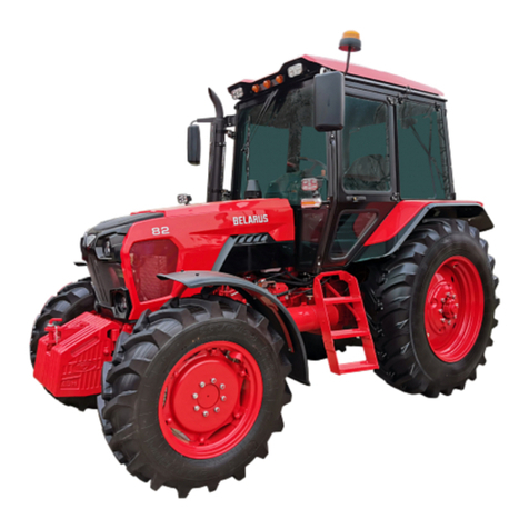
Belarus 920.4 User manual

BELARUS
920.4/952.4
WITH ENGINE
D-245.43S3A/D-245.5S3A
920.4-0000010 OM
OPERATING MANUAL
(Supplement to operating manual for
BELARUS 920.3/952.3 tractors)
MTW 2009
https://tractormanualz.com/

BELARUS-920.4/952.4 Operating manual
2
CONTENTS
1 Tractor description and operation..............................………………………………..……… 4
1.1 Tractor designation ….……………..……………………………………………………… 4
1.2 Technical characteristics ………………………....……………………………………….. 4
1.2.1 General description ……………………………………………………………...………. 4
1.2.2 Main parameters and characteristics ……………………………………………………..5
1.3 Tractor structure and operation ……………………………...……………………………. 9
1.3.1 Controls and Instruments...………………………………………………………………. 9
1.3.2. Switch of starter and instrume
n
ts ……………………………………………...…………9
1.3.3. Instrument cluster ……...….…………………………………….……………………… 10
1.3.4. Pilot lamp unit …………………..…………………………………………………….…12
1.3.5. Integrated display.………………………………………...…………………………….. 13
1.3.6. Designation and principle of operation of integrated display indic
a
tors.………………. 13
1.3.7. Integrated display pilot lamps..………………...………….……………………………. 17
1.3.8 Description of instrument function check …………….……………………………….....17
1.3.9 Integrated display program console ……………………...……………………………. 18
1.3.10 Dashboard switches …………………………….……………………………………… 20
1.3.11 Climate system control …...………………………….……………………………....… 21
1.3.12 Double-lever gear box control ……………………………………………………....…. 21
1.3.12.1 General information……………………………………….……………………..….... 21
1.3.12.2 Shifting of ranges and gears in GB with double-lever control ………......................... 22
2 Tractor components description and operation……………………………………………….24
2.1 D-245.43S3А/D-245.5S3Аengine..…………………………………….…………………. 24
2.2 Electronic engine control system for D-245.43S3А(D-245.5S3А)……………………….. 24
2.2.1 General Information………………………………………………………………………24
2.2.2 Adjust brightness and contrast of display indicator…………………………………….. 26
2.2.3 Call up changeable presentations and parameters to display……………………………. 26
2.3 Wet brakes and rear axle differential lock clutch……………………………………………. 29
2.3.1 General infor
m
ation………………………………………………………………………29
2.3.2 Wet service and park brakes, wet brakes control…………………………………….…...30
2.3.3 Differential lock wet clutch ……………………………………..………………………. 30
2.4 Trailer brake drive …………………………………………………….……………………. 31
2.4.1 General information………………………………………………………………………31
2.4.2 Combine
d
trailer brake pneumatic drive ……………………………………………….. 31
2.4.2.1 General information…………………………………………………………………….31
2.4.2.2 Check and adjust drive of single-wire and two-wire brake valves of pneumatic syste
m
33
2.4.3 Trailer brake hydraulic drive ………………………………………………………….. 34
2.4.3.1 General information…………………………………………………………………….34
2.4.3.2 Adjustment of trailer brake hydraulic drive ……………………….............................. 36
2.5 Cab air conditioning and heating syste
m
…………………………..................................... 37
2.5.1 Climate system control in air conditioning mode ………………………………………. 37
2.5.2 Climate system control in heating mode ……………………………………………….. 37
2.5.3 General arrangement and operation of cab air conditioning and heating syste
m
……….. 38
2.5.4 Air conditio
n
ing unit troubleshooting …………….......................................................... 41
2.6 Electric equipment ………………………………………………………………………... 41
3 Maintenance …………………………………………………………………………….…... 42
3.1 Maintenance of tracto
r
…………………………………………………………………..… 42
3.2 Maintenance of tractor components ………………………………………………………. 43
Annex А……………………………………………………………………………………… 49
Annex B……………………………………………………………………………….............. 56
https://tractormanualz.com/

BELARUS-920.4/952.4 Operating manual
3
The operating manual is intended for study of arrangement, operating rules and mainte-
nance of the tractors Belarus 920.4 / 952.4.
The present manual is a supplement of operating manual 900–0000010 OM and should be
enclosed together with this manual.
Read carefully through this manual, operating manual 900–0000010 OM, operating manual
for diesel engine 245 S3A – 0000100 OM, enclosed with your tractor. It will help you to get ac-
quainted with methods of proper operation and maintenance.
Failure to follow this instruction can result in operator’s injuries and tractor breakings.
Tractor operation, its maintenance and repairing must be carried out only by the specialists,
acquainted with all its characteristics and informed about necessary safety requirements to prevent
accidents.
Due to constant development of tractor, changes, which are not shown in the present oper-
ating manual, can be introduced into design of some assembly units and parts.
All unspecified changes, introduced into structure of any assembly units by the consumer,
release the manufacturer from responsibility for subsequent operator’s injuries and tractor break-
ings.
Accepted abbreviations and legend
ECM – Engine control module;
FPFV – frequency probe of fuel volume
ID – Integrated display;
MD – Multifunction display;
IDPC – Integrated display program console;
OM – Operating manual.
Other abbreviations and legend are given in Operating manual 900–0000010 OM.
https://tractormanualz.com/

BELARUS-920.4/952.4 Operating manual
4
1 TRACTOR DESCRIPTION AND OPERATION
1.1 Tractor designation
Tractor “BELARUS - 920.4” is manufactured on the base of tractor “BELARUS - 920.3”.
Tractor “BELARUS - 952.4” is manufactured on the base of tractor “BELARUS - 952.3”.
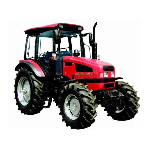
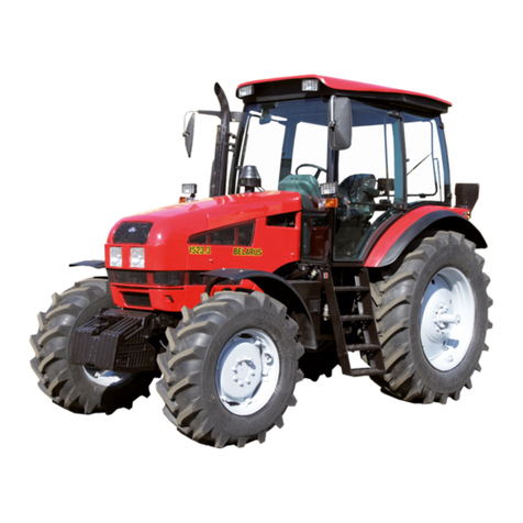
Tractors “BELARUS - 920.4 / 952.4” are designed for executing various agricultural works
with mounted, semi-mounted and trailed machines and implements, for loading-unloading works,
transportation works and for driving stationary agricultural machines; they are supplied to con-
sumers in the Republic of Belarus and abroad.
1.2 Technical characteristics
1.2.1 General description
The tractors “BELARUS - 920.4/952.4” represent universal row-crop tractors of drawbar
category 1.4.
The tractors “BELARUS - 920.4” are equipped with engine D-245.43S3А, produced by
Minsk motor works, with electronic control system, with power of 62 kW. Engine conforms to en-
vironmental requirement of stage III A according to harmful substance emission.
Tractors “BELARUS - 952.4” is equipped with engine D-245.5S3А, produced by Minsk
motor works, with electronic control system, with power of 70 kW. Engine conforms to environ-
mental requirement of stage III A according to harmful substance emission .
Clutch coupling: friction, single-disk, closed-circuit, mechanically controlled.
Clutch facings: cerametallic.
Gearbox: mechanical, synchronized, with synchronized accelerator, doubling number of
gears.
Rear axle: with main gear, differential and final drives. Differential lock control: electrohy-
draulic.
Front driving axle: with main gear, self-locking differential, final drives (planetary-
cylindrical reduction gears). Front driving axle drive: transfer case with automatic engagement of
FDA, two cardan shafts and intermediate bearing with overload clutch.
Service brakes: multidisk, oil-bath lubricated (“wet”), installed on the shafts of driving pin-
ions of hub drives; parking brake – independent, with independent manual control.
Trailer brake drive: hydraulic, interconnected with tractor brake control or combined
pneumatic drive interconnected with tractor brake control.
Hydraulic system: remote-cylinder with hydraulic hoist, with rear right-hand duplicated
outlets of hydraulic system.
Rear lift linkage NU-2, with adjustable braces; NU lower links: telescopic; rod interlock-
ing: outer, by means of telescopic tie-rods.
Rear power take-off shaft (PTO): separate, two-speed (540 and 1000 min-1) and synchro-
nous, rotation direction – clockwise from the side of shank end. PTO shanks: PTO 1 (6 or 8
splines, 540 min-1), PTO 2 (21 splines, 1000 min-1).
Cabin: unified, protection, securing safety, microclimate, protection against noise and vi-
bration. Cabin is equipped with an electric wipers for front and rear windows and front window
washer, climatic unit and cabin heater, Grammer sprung seat, adjustable according to operator’s
height and weight. Additional front working headlights are installed on the brackets of front lamps.
https://tractormanualz.com/
BELARUS-920.4/952.4 Operating manual
5
1.2.2 Main parameters and characteristics
1.1.2 Main parameters and characteristics are specified in Table 1
Table 1
Parameter (characteristic) designation Value for tractor “BELARUS”
920.4 952.4
1 Drawbar category according to
GOST 27021 1,4
2 Force exerted rating, kN 14
3 Engine:
a) Model D-245.43S3АD-245.5S3А
b) Type Turbocharged
c) Cylinder number and arrangement 2
)
Four, in-line, vertical
d) Displacement volume, l 4,75
e) Power, kW:
1) rated
2) normal
f) Crankshaft rated speed, rpm
g) Specific fuel consumption at nomi-
nal power, g/(kWh)
62,0 2,0
58,72,0
1800
2205,0/
70,02,0
66,72,0
1800
2205,0
h) Rated ratio of torque backup, %
25
i) Specific oil consumption for
burn-out, measured according to
GOST 18509, g/(kWh)
0,3+0,2
j) Peak torque, Nm 411 464
4 PTO power at PTO mode “540
rpm”, at least kWh 58,3
5 Specific fuel consumption at PTO
power in PTO mode “540 rpm”, at
least g/(kWh)
248
6 Number of gears:
а) forward
14
b) reverse 4
7 Tractor (design) speed on basic con-
figuration tires at rated engine crankshaft
speed, km/h:
а) forward:
1) minimum operating speed
2,65
2) maximum traveling speed 38,1
b) reverse:
1) minimum 5,58
2) maximum 12,57
https://tractormanualz.com/

BELARUS-920.4/952.4 Operating manual
6
Cont. of Table 1
Parameter (characteristic) designation Value for tractor “BELARUS”
920.4 952.4
8 Tractor weight, kg:
a) structural weight 4150 ± 100
b) operating weight 4450 ± 100
c) maximum operating weight 7000
d) shipping weight 1) 4250
9 Maximum of the average nominal
floor pressures of driving machines, MPa
0,14
10 Operating weight distribution over
the axles, kg:
a) front axle 1750 ± 50
b) rear axle 2700 ± 50
11 Allowable axle load, kN:
a) front axle 37,0
b) rear axle 53,0
12 Maximum weight of towed trailer
(trailer brakes are interconnected with
tractor brakes), kg
9000
13 Agrotechnical clearance under
front axle, rear-axle and front-axle tubes,
when interlocking of lift linkage lower
rods is installed, at least mm:
510
14 Wheel track dimension, mm:
а) front wheels 1420-1970
б) rear wheels 1500-1600,
1800-2100
15 Minimal radius of turning in the
middle of the outer front wheel mark at
minimum wheel track applying partial
braking of the inner rear wheel, m
4,5
16 Tractor wheelbase, mm 2450±20
17 Maximum fordable depth, m 0,85
18 Nonrefuelling continuous work du-
ration at 80 % engine load, at least h
10
19 Mean time between failures of II
and III complexity groups over the war-
ranty period, at least h
500
https://tractormanualz.com/

BELARUS-920.4/952.4 Operating manual
7
Cont. of Table 1
Parameter (characteristic) designation Value for tractor “BELARUS”
920.4 952.4
20 Specific total operational mainte-
nance burden, at least man –hour/h
0,026
21 Service life period, years 10
22 Overall dimensions, mm:
a) length with ballast weights and rear
lift linkage in transit condition
4440± 50
b) length without ballast weights, with
lift linkage in transport position
4060± 50
c) length over external diameters of
wheels
3850± 50
d) width over the ends of rear wheel
semi-axles
1970± 50
e) cab height 2850± 50
23 Tires (basic configuration):
Front 360/70R24
Rear 18.4R34
24 Steering:
a) steering wheel turning effort, when
feeding pump is operating, not more than
N b) number of steering wheel revolu-
tions, ensuring complete angle of guide
wheel turning, at least
c) steering wheel backlash (free play),
when feeding pump is operating, at least
30
6
25º
d) steering wheel adjustment range:
1) adjustment for tilt angle to the hori-
zon with four position fixation
2) height adjustment along the steering
shaft axis, mm
25º - 40º
100±20 steplessly
25 Electrical system
a) operating supply voltage of onboard
network, V
12
b) rated starting voltage, V: 24
26 Working equipment:
a) rear PTO
1) PTO shank speed
with separate drive, rpm:
- I speed 540
- II speed 1000
https://tractormanualz.com/

BELARUS-920.4/952.4 Operating manual
8
End of Table 1
Parameter (characteristic) designation Value for tractor “BELARUS”
2) PTO shank speed with synchronous
drive, rev. per meter of travel 3,2
For tires
18.4R34
b) rear lift linkage:
1) lifting capacity of rear lift linkage
on suspension axle, at least kg
2) pump volume feed at rated engine
crankshaft speed, at least l/min
4000
45
3) hydraulic system pressure relief
cracking pressure, MPa
20-2
4) conditional volume factor of hy-
draulic system (efficiency factor), at least
0,65
5) lifting time for rear lift linkage from
the lowermost position into uppermost
position with test load on the suspension
axle, s, at least
2,2
c) drawbar hitch:
1) virtual displacement of coupling
point, mm:
- in horizontal plane relative to tractor
longitudinal axis
- in vertical plane relative to ground
surface on the basic configuration tires,
mm:
2) distance between PTO end and tow-
ing yoke hole axis, mm
3) opening, mm:
- depth
- height
160 with intervals of 80±5
200 – 500
395±10
65±2
62±2
1) To be specified depending on the configuration.
https://tractormanualz.com/

BELARUS-920.4/952.4 Operating manual
9
1.3 Tractor structure and operation
1.3.1 Controls and Instruments
This operating manual gives description and principle of operation of only controls and in-
struments, specified in section 1.3.1. Location, designation and principle of operation of other con-
trols (levers, pedals, key switches, etc.) are similar to BELARUS-920.3/952.3 and are represented
in Operating manual RE 900-0000010, attached to tractors BELARUS -920.4/952.4.
1 – Control handle of heater control valve;
2 – Climatic installation control panel;
3 – Deflectors;
4 – Switch of starter and instruments;
5 – Remote battery disconnect switch;
6 – Windshield washer switch;
7 – Main light switch;
8 – switch of front headlights installed on brackets of front lights;
9 – Switch of hazard warning flasher;
10 – Multi-function underwheel switch (turn indicator, high/low beams, horn, signaling with high
beam);
11 – Instrument cluster;
12 – Signal lamp unit;
13 – Integrated display;
14 – Program console of integrated display.
Figure 1.1 – Controls and instruments
1.3.2. Switch of starter and instruments
Switch of starter and instruments 4 (Fig. 1) has four positions:
• 0 — Switched off;
• I — Instruments, pilot lamp unit, glow plugs are switched on;
• II — Starter is switched on (non-retained position);
• III —Radio receiver is on (the key turned counterclockwise).
https://tractormanualz.com/

BELARUS-920.4/952.4 Operating manual
10
Figure 1.2 – Switch of starter and instruments
ATTENTION: STARTER REENGAGEMENT IS POSSIBLE ONLY AFTER RETURN-
ING THE KEY TO “0” SWITCH POSITION. TO MOVE THE SWITCH OF STARTER AND
INSTRUMENTS INTO “III” POSITION IT IS NECESSARY TO FORCE THE KEY INTO THE
SWITCH AND TURN IT COUNTERCLOCKWISE.
1.3.3 Instrument cluster
Instrument cluster 11 (fig. 1.1) includes five indicators with alarm lamps (fig. 1.3).
1 – Fuel gauge;
1.1 – Reserve fuel level alarm lamp;
2 – Pneumatic system air pressure gauge;
2.1 – Emergency pneumatic system pressure alarm lamp;
3 – Voltage indicator;
3.1 – Indicator lamp of additional battery charging;
4 – Engine coolant temperature gauge;
4.1 – Engine coolant temperature alarm lamp;
5 – Engine lubricating system oil pressure indicator;
5.1 – Alarm lamp of emergency engine lubricating system oil pressure.
Figure 1.3 – Instrument cluster
https://tractormanualz.com/

BELARUS-920.4/952.4 Operating manual
11
Scale of fuel gauge 1 (Fig. 1.3) has sections 0 – 1/4 – 1/2 – 3/4 – 1.
Alarm lamp 1.1 is built into the gauge scale (Fig. 1.3) (orange), which lights up when fuel quantity
in tank drops down to 1/8 of total tank capacity.
ATTENTION: AVOID USING THE FUEL TO REACH THE STATE OF “DRY TANK” (IN-
DICATOR NEEDLE IS IN ORANGE AREA)
Scale of pneumatic system air pressure gauge 2 (Fig. 1.3) has three areas:
- operating area – from 500 to 800 kPa (green);
- emergency area (two) – from 0 to 500 kPa and from 800 to 1000 kPa (red).
Alarm lamp 2.1 (Fig. 1.3) (red) is built into the gauge scale, and it lights up when pneumatic pres-
sure drops down below 500 kPa.
Voltage indicator 3 (Fig. 1.3) shows storage batteries voltage with shut-down engine, when the switch
key of starter and instruments (Fig. 1.2) is in I position. When the engine is running, voltage indicator
shows voltage across generator terminals. Red alarm lamp 3.1 (Fig. 1.3) is built into the voltage in-
dicator scale. It is used only in 24V starting system, shows the charging process of the second stor-
age battery with 24V voltage, tests performance of voltage converter.
State of power-supply system
Table 2
Area on the scale of voltage
indicator 3 (Fig. 1.3), color State of power-supply system
with running engine with shut-down engine
13.0 – 15.0 V
green normal charging func-
tion -
10.0 – 12.0 V
red generator is out of oper-
ation Storage battery is discharged
12.0 – 13.0 V
yellow no storage battery charg-
ing (low charging voltage) Storage battery has normal charge
15.0 – 16.0 V
red Overcharging of storage
battery -
white matchmark in yellow
area - Rated EMF of Storage battery – 12.7 V
ATTENTION: IF VOLTAGE INDICATOR DISPLAYS ABSENCE OF STORAGE BATTERY
CHARGING, CHECK THE STATE AND TENSION OF GENERATOR DRIVING BELT
Engine coolant temperature gauge 4 (Fig. 1.3) reads information from engine control module
(ECM). Gauge scale has three areas:
- operating area — from 70 to 100 °С(green).
- information area — from 40 to 70 °С(yellow)
- emergency area — from 105 to 120 °С(red).
High temperature alarm lamp (red) 4.1 (Fig. 1.3) is built into the gauge scale, it works in two
modes:
a) – lights up and works in a flashing mode at coolant temperature values from 109 to 112 °Сin-
clusive.
b) – is constantly glows at coolant temperature values from 113 °Сand above.
Engine lubricating system oil pressure indicator 5 (Fig. 1.3) reads information from engine control
module (ECM). Gauge scale has three areas:
- operating area — from 100 to 500 kPa (green);
- emergency areas (two) — 0 to 100 kPa and from 500 to 600 kPa (red).
https://tractormanualz.com/

BELARUS-920.4/952.4 Operating manual
12
Alarm lamp of emergency oil pressure drop (red) 5.1 (Fig. 1.3) is built into the gauge scale, and lights
up when oil pressure drops below 100 kPa.
Note – During the cold engine starting the pressure can come up to 600 kPa.
Attention: IF LOW PRESSURE LAMP IS ON WITH THE ENGINE RUNNING, STOP THE
ENGINE IMMEDIATELY AND ELIMINATE THE MALFUNCTION.
1.3.4. Pilot lamp unit
The pilot lamp unit 12 (fig 1.1) is located on the dashboard and includes three lamps.
Layout chart of pilot lamps corresponds to Figure 1.4.
Figure 1.4 – Pilot lamp unit
Principles of pilot lamps operation shown in Figure 1.4 are described in the 900–
0000010 OM.
https://tractormanualz.com/

BELARUS-920.4/952.4 Operating manual
13
1.3.5. Integrated display
Integrated display 13 (Fig. 1.1) (hereafter - ID) and program console of integrated display 14
(Fig. 1.1) (hereafter - PU) display information on performance parameters of tractor systems and
assemblies and provide operator with data on malfunction and failure of some system.
ID includes indicators and announciating lamps according to Figure 1.5:
1 – speedometer (needle indicator);
2 – tachometer (needle indicator);
3 – PTO tachometer (indicator lamp);
3.1, 3.5 – segments of PTO speed scale (yellow);
3.2, 3.3, 3.4 – segments of PTO speed scale (green);
4.1, 4.2– announciators of PTO speed scale ranges (yellow);
5 – high-beam pilot lamp-indicator (blue);
6 – trailer turn pilot lamp – indicator (green);
7 – tractor turn pilot lamp – indicator (green);
8 – parking brake pilot lamp – indicator (red);
9 – high on-board voltage pilot lamp-indicator (red);
10 – low coolant level pilot lamp-indicator (yellow);
11 – multifunction display;
Figure 1.5 – Integrated display
1.3.6. Designation and principle of operation of integrated display indicators
a) 1 (Fig. 5) – speedometer – displays design tractor speed on needle indicator. Design
speed is higher than actual speed as far as tractor skidding is not considered.
https://tractormanualz.com/

BELARUS-920.4/952.4 Operating manual
14
The indicator works upon signals from pulse sensors of final drive tooth gear speed of left
and right rear tractor wheels. Speed is indicated upon a signal from the sensor, installed on final
drive gear of the wheel, rotating at lower speed.
If one of speed sensors is defective, integrated display shows speed readouts with speed-
ometer upon the signal from nondefective sensor. On LCD display of ID specific malfunction of
circuits or speed sensors, if signals from them are missing, is represented in the form of digit “0”,
which defines malfunction location, to the left and to the right (see below).
b) 2 (Fig. 1.5) – tachometer, displays engine crankshaft speed on needle indicator.
Information on engine speed on tractors BELARUS-952.4/920.4 comes from electronic con-
trol module. Speed readouts range is from 0 to 3500 (rpm).
c) 3 (Fig. 1.5) – PTO tachometer displays PTO speed on indicator lamp.
PTO tachometer operates upon the frequency signal, resulting from recalculation of engine
speed by means of entered value of index “KV2” (see below), other than “0”, meanwhile value of
index “ZV”, equal to “0”, should be entered (see below).
When ID is switched on (see below the description of device functional check) and engine
is running (message “engine speed” from ECM is transmitted) identifications of scales “540” and
“1000” are illuminated simultaneously.
Indication of PTO scale segment (with regard to the entered value of index “KV2”) occurs
when PTO rated speed, equal to 750 rpm, is achieved.
For reference:
indication of lower PTO scale segment (with regard to index “KV2”) occurs when engine
speed of 1400-1500 rpm and above is achieved.
According to selected PTO speed mode (540 or 1000) illuminated scale segments identify
value of PTO speed in accordance with given table 3.
Table 3 “540” “1000” Segment location on
scale
650 1150 3.1
580 1050 3.2
500 950 3.3
420 850 3.4
320 750 3.5
“PTO speed” mode of liquid-crystal display 11 of multifunctional display (Fig. 1.5) (see
below the description of multifunctional display operation) is not active in this case.
d) 11 (Fig. 1.5) - multifunctional display (MD) is a liquid-crystal display, displays infor-
mation in two fields at the same time (see fig. 1.6):
https://tractormanualz.com/

BELARUS-920.4/952.4 Operating manual
15
“1” – digital identification of transmission switch position (digits from 0 to 6) or letter identifica-
tion of reduction unit switch position (letters L, M, H, N);
“2” – current numerical value of one of tractor system parameters
Figure 6 – MD information fields
Integrated display receives information on transmission switch position from transmission control
module (if combined electronic control system (CECS) is available) or from range reduction unit
control module (if available). This parameter is displayed in information field “1” (Fig. 1.6). If
control modules are not available or are not connected or wire is broken, letter “A” is displayed in
the information field “1”.
Following parameters are displayed in information field “2” (Fig. 1.6):
- Total elapsed operating time of engine;
- Instantaneous fuel consumption;
- On-board system voltage;
- Remaining fuel volume;
- Operation time with remaining fuel;
- Operability diagnostics of speed sensors;
- Operability diagnostics of frequency probe of fuel volume (FPFV)
- Diagnostics of operability and connection of CAN-bus to ID.
Selection of display modes among “Total elapsed operating time of engine”, “Instantaneous fuel
consumption”, “Remaining fuel volume”, “Operation time with remaining fuel”, “On-board sys-
tem voltage”, failure messages is made with “Mode” button of program console 14 (Fig. 1.1). De-
scription of operation algorithms of modes “Operability diagnostics of speed sensors”, “Operabil-
ity diagnostics of frequency probe of fuel volume (FPFV)”, “Diagnostics of operability and con-
nection of CAN-bus to ID” is given above.
1. Total elapsed operating time of engine in hours.
Counter amasses information on total time of engine opera-
tion when message “engine speed” is transmitted from ECM
and stores it when power supply is disconnected.
Readout range is from 0 to 99999 of engine operating hours.
2. Instantaneous fuel consumption
This mode displays current value of instantaneous fuel consumption,
readout resolution is 0,1 l/h.
https://tractormanualz.com/

BELARUS-920.4/952.4 Operating manual
16
3. On-board system voltage
This mode displays current value of system voltage in digital form.
4. Remaining fuel volume
This mode displays current fuel amount in tank in liters.
This mode is available only on stopped tractor (when there are no signals
from speed sensors).
Note: Tractor should be stopped on horizontal surface in order to increase
displaying accuracy of fuel amount in tank.
5. Operation time with remaining fuel
This mode displays anticipated time of engine operation, calculated for
current values of instantaneous fuel consumption and remaining fuel.
ID in the mode of failure messages displaying
1. Diagnostics of speed sensor operability and connection:
When signals from speed sensors are missing for
10-12 seconds, LCD display shows a message in
form of digit “0”, characterizing location of de-
fective sensor (left of right).
2. Operability diagnostics of frequency probe of fuel volume (FPFV):
When frequency signal from FPFV is missing for 2 seconds, LCD display
of ID displays “FUEL” message.
3. Diagnostics of operability and connection of CAN-bus to ID with СAN interface:
Absence of signal in CAN-bus (ID) is accompanied with “C-BUS” mes-
sage.
Every failure message (Example: 0---, FUEL, C-BUS) is displayed on LCD display in priority ir-
respective of information displayed. When pressing “Mode” button consecutively, there should be
messages paging. When viewing the last message and pressing “Mode” button again, LCD display
proceeds to the mapping mode according to the cycle of previously specified operating parameters.
https://tractormanualz.com/

BELARUS-920.4/952.4 Operating manual
17
Failure message displaying on LCD display occurs during every switching on of the device up to
the moment of failure cause removal.
Notes:
1 – When powering on the ID, MD displays information in indication mode, selected before the
moment of ID power shut-down.
2 – If there is no information on parameter values, which are received from ECM only, corre-
sponding indication modes switch off automatically.
1.3.7. Integrated display pilot lamps
“ATTENTION: PILOT LAMP-INDICATORS SWITCH ON AND OFF SYNCHRONOUSLY
WITH CHANGES OF SYSTEM SENSOR STATES”.
a) 5 (figure 1.5) – headlight high-beam pilot lamp-indicator.
Illuminates when headlight high beam is switched on.
b) 6, 7 (figure 1.5) – tractor and trailer turn pilot indicators. Operate in flashing mode when right or
left turn signal is switched on by multi-function underwheel switch 10 (figure 1.5), or when the
switch of hazard warning lights is on.
c) 8 (figure 1.5) – parking brake pilot lamp-indicator. “Parking brake” indicator operates in flash-
ing mode with 1 Hz frequency, when parking brake sensor goes off;
d) 9 (figure 1.5) – high on-board system voltage pilot lamp-indicator. Switches on when tractor on-
board system voltage exceeds 19V and goes out when supply voltage level goes down to 17V;
In this case ID switches off completely, and recovers its operational capability when the
voltage goes down to rated value of on-board system voltage.
e) 10 (figure 1.5) – coolant low level pilot lamp-indicator. Lights up when coolant level in recovery
bottle drops below 20% of general level.
1.3.8 Description of instrument function check
In the course of every connection to power supply, needle indicators and elements of PTO indica-
tor scale in the ID are checked for functioning. And during a second at most indicator needles de-
viate from initial marks and run over the first following digitized scale marks (over “5” for the
speed and over “10” for revolutions), and all segments and indications “540” and “1000” of PTO
scale are activated.
https://tractormanualz.com/

BELARUS-920.4/952.4 Operating manual
18
1.3.9 Integrated display program console
Program console 14 (figure 1.1) allows to perform manual pro-
gramming of indicator by means of “Parameter” and “Value”
buttons (see figure 1.7), to change the displaying mode for pa-
rameters, displayed on LCD display.
Note – There is a diagnostic slot XP1 on console front surface
that allows to perform automatic programming (reprogram-
ming) of ID by means of a special instrument (if available). If it
is not available reprogramming is performed by means of the
buttons mentioned above. XP1 is not enabled on tractors “Bel-
arus-952.4/920.4”.
Figure1.7 – Integrated display program console
ID programming algorithm
1. When selecting specified value of programming parameter:
1.1 When pressing “Parameter” button for the first time (see figure 7), LCD display goes to the
mode of viewing the programmed parameter identification and its numerical value. Cyclic change
of parameters occurs during the repeated button pressings.
1.2 When consecutively pressing “Value” button (see figure 7) numerical value of set programmed
parameter changes.
1.3 Mode exit is fulfilled automatically when “Parameter” and “Value” buttons have not been
pressed for 7 sec.
In case of mode exit the last parameter values, selected with “Value” button, are stored.
2. When entering non-specified value of programming parameter:
2.1 Select parameter, which value needs to be set up, with “Parameter” button;
2.2 Press “Mode” button twice, least significant digit of numerical value will start flashing on LCD
display;
2.3 The value of flashing parameter digit should be changed by pressing “Value” button;
2.4 Transfer to more significant digit is fulfilled by pressing “Parameter” button;
2.5 Exit from the programming mode of non-specified value of any parameter is accomplished by
double pressing of “Mode” button;
2.6 After the exit from the said mode digits of the entered parameter value stop operating in flash-
ing mode;
2.7 New entered value is placed as the last in the list of parameter values, allowed for program-
ming;
Note:
- in case of single pressing of “Mode” button in programming mode, it is not possible to en-
ter arbitrary value of parameter;
- if “Mode”, “Parameter” and “Value” buttons have not been pressed for 7 seconds in the
mode of entering non-specified value of parameter, ID goes to main mode of LCD display opera-
tion saving set parameter values.
https://tractormanualz.com/
BELARUS-920.4/952.4 Operating manual
19
It is allowed to enter one non-specified value within the range:
for «Z» - from 23 to 69;
for «I» - from 1.000 to 4.000;
for «R» - from 400 to 1000;
for «K» - from 2.360 to 4.000; (For ID without CAN-interface)
for «KV2» - from 0.346 to 0.600;
for «ZV» - from 12 to 78;
for «V» - from 0 to 600.
List of programmed coefficients (graphic examples of displaying parameters and their values in
programming mode):
Parameter “Z”
Z – number of gear teeth of final shafts of driving wheels (right and left),
above which speed sensor (sender) are installed;
Parameter “I”
I – raising ratio correction factor of wheel-hub drive;
Parameter “ R”
R – rear wheel rolling radius, mm. In case of reprogramming it is possible
to change this parameter with 5 mm increment.
Note: 770 is the value for tires 18.4R34. In case of new types of tires set
the parameter "R” value which corresponds to rolling radius of installed
tires.
Parameter “ KV2”
KV2 – power take-off shaft (PTO) ratio;
Parameter “ZV”
ZV – number of gear teeth of PTO speed sender
(Note – if the sender is not installed, “0” value should be entered)
Parameter “V”
V – fuel tank volume, l.
Also in programming mode when pressing on “Parameter” button in the
list of programmed parameters independent parameter “T” of refined con-
tent of astronomical engine operating time meter is displayed. This param-
eter can not be changed, it gives precise value (up to 1/10 hour) of engine
operating time.
https://tractormanualz.com/
BELARUS-920.4/952.4 Operating manual
20
During the operational process it is allowed to change the value of parameter “wheel rolling
radius R” that is defined on the basis of tires, installed on tractor, by measuring the distance be-
tween wheel center and supporting surface.
IT IS PROHIBITED TO CHANGE ENTERED VALUES OF EVERY OTHER PARAM-
ETERS (FACTORY SETTINGS).
When switching on the instrument dial illumination, i.e. when shifting main light switch 7
(Figure 1.1) into position II “Dash panel illumination and side-marker lights are turned on” and
position III “Consumers of II position and front road headlamps are turned on” light intensity of
MI display of PTO indicator segments reduces automatically.
1.3.10. Dashboard switches
a) 5 (Figure 1.1) – remote battery disconnect switch. When pressing the button (unfixed) of remote
battery disconnect switch, storage batteries switch on, and after repeated pressing they switch off.
b) 6 (Figure 1.1) – windshield washer switch. When pressing the button (unfixed), windshield
washer switches on.
c) 7 (Figure 1.1) – main light switch, has three positions:
— “Switched off” (upper part of the button in the photo is sunken, I position);
— “Front marker and tail, license plate and instrument panel lights as well as additional lights on
trailed machine are switched on” (middle position, II);
— “All consumers of II position and road headlamps are switched on” (lower part of the button in
the photo is pressed to the full, III).
d) 8 (Figure 1.1) switch of front headlights installed on brackets of front lights. When the key 8 is
pressed, two front headlights (located on brackets of front lights) and the light indicator built into
the key are switched on.
e) 9 (Figure 1.1) – switch of hazard warning flasher. Pressing the button actuates hazard warning
flasher. Control lamp, built into the button, flashes simultaneously with flashing warning light.
Hazard warning flasher shuts down after repeated pressing the button 9.
f) 10 (Figure 1.1) – Multi-function switch (under steering wheel). Secures the switching-on of turn
signals, low/high beam of road headlamps, signaling (flashing) with high beam and horn.
Turn signals switch on when lever is shifted forward (“a” – right turn) or backward (“b” –
left turn) from middle position in accordance with figure 1.8. After tractor makes a turn, the lever
returns to initial position automatically.
To switch on road headlamps, set main light switch 7 (Figure 1.1) into III position (see above)
and switch lever into middle position “c” – “low beam” in accordance with figure 1.8. “High beam”
should be switched on by turning the switch lever forward as far as it will go (“d” position).
“Low”/”High” beam positions of the lever are fixed.
When pulling the lever backward as far as it will go (“e” position, Figure 1.8) from “low
beam” position, unfixed switching-on of high beam, “high beam flashing” occurs, irrespective of
main light switch position.
https://tractormanualz.com/
This manual suits for next models
1
Table of contents
Other Belarus Tractor manuals

Belarus
Belarus 510 User manual

Belarus
Belarus 1220.6 User manual

Belarus
Belarus 2022.6 User manual

Belarus
Belarus 1822.3 User manual

Belarus
Belarus 3522.5 User manual

Belarus
Belarus 922.6 User manual

Belarus
Belarus 1523.6 User manual

Belarus
Belarus 1025 2008 User manual

Belarus
Belarus 2122.6 User manual

Belarus
Belarus 1523.5 User manual