System description
12 TGH1390en/04.2011
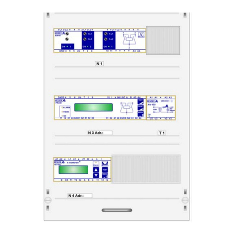
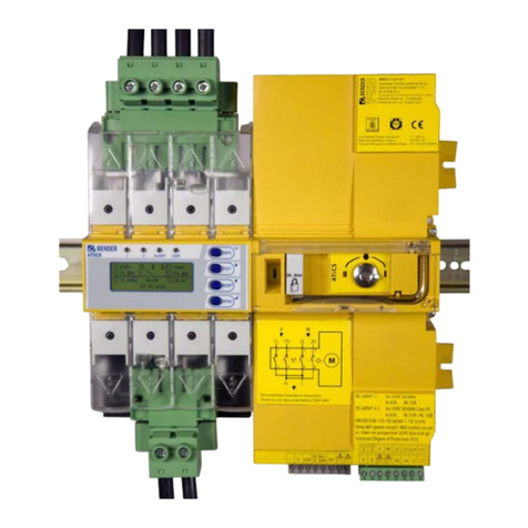
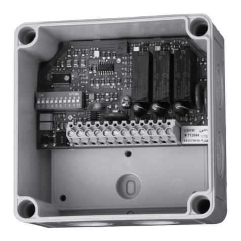
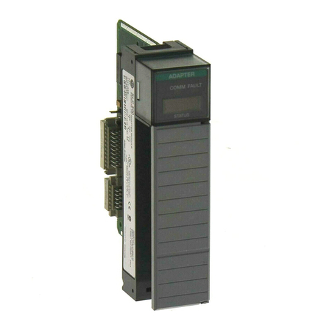
The USC710D4-..-HA control module provides the following possibilities:
1. It is designed to be operated with the TMX-HA alarm indicator and operator panel. That addi-
tionally allows manual operation of the changeover and monitoring module which is required,
for example, for revision procedures. When operated in manual mode, an alarm message
occurs on the control module or via BMS bus on associated remote alarm indicators and test
combinations MK… or TM… operator panels. Note: The alarm indicator and operator panel
TMX-HA is not included in the scope of delivery.
2. Alternatively, messages about internal operating statuses can be assigned to specific relays.
That requires the setting of specific parameters on the PRC487. When a TMX-HA alarm indica-
tor and operator panel is used and additional alarm contacts are required, a URC-11 resp. URC-
14 relay module is to be used for the purpose of contact expansion.
3. Optional switching back interlocking function (see chapter “4.2.1 Typical connection”).
3.3.2 Version for generator operation
The USC710D4-03 and USC710D4-04 control modules are designed for generator operation, i.e. line
2 is to be supplied by a generator. In normal condition, line 2 is deenergised. Therefore, the message
"Failure line 2“ remains deactivated as long as the generator is switched off.
Behaviour in the event of failure of line 1
If line 1 fails, the USC710D4-03-HA and USC710D4-04-HA control modules initiate a start-up signal
for the generator. For this purpose, an output in N/C operation is available at the terminals X4:3, X4:4
and X4:5. In normal condition, the contacts X4:3 X4:4 are open, if line 1 fails, the contacts will close.
Generator test
For running a generator test under load, the USC710D4-03-HA and USC710D4-04-HA control mod-
ules provide a control input for initiating a generator start-up and a changeover process whilst the
generator is supplying line 2.
By applying a control voltage of AC/DC 12…240 V to the terminals X4:1 (+) and X4:2 (-), a failure of a
line conductor of line 1 is simulated and the alarm message "Failure line 1“ is generated. The start-up
of the generator is initiated.
Change-over to line 2 will take place as soon as line 2 is energised. This will only be the case if the
generator has booted up correctly and line 2 is being supplied.
Precondition for reliable function in the event of generator operation:
tNG > t(off) N19 > t(on) N3
-The disconnecting delay time the generator tNG needs (from voltage recovery
on line 1 until the generator is shuts off) must be greater than the response time
t(off) set at the voltage relay N19 (factory setting 20 s).
-The response time t(off) at the voltage relay N19 must be greater than the return
transfer time t(on) of the changeover module (PRC487 – N3 factory setting 15 s).


