Bender EDS44 L-CN Series User manual
1
快速操作手册 / Quick-start guide
CN EN
Insulation fault locator
This quick-start guide applies to the EDS440/441-L-CN, W-L-CN,
-S-CN, W-S-CN, EDS441-LAB-4-CN and W-CN devices. It does not
replace the operating manual.
The operating manual can be found on our homepage under
www.bender.de/manuals.
Intended use
The insulation fault locator EDS44… locates insulation faults in
ungrounded DC, AC and three-phase supplies (IT systems).
With an active test current generator (PGH), AC and three-phase
networks in the range AC 0…1000 V and DC networks in the
range DC 0…1500 V can, depending on the PGH type, be monito-
red. An AC residual current in the range 42 Hz…1 kHz, 100
mA…20 A (EDS440) or 50/60 Hz, 100 mA…2 A (EDS441) can be
displayed.
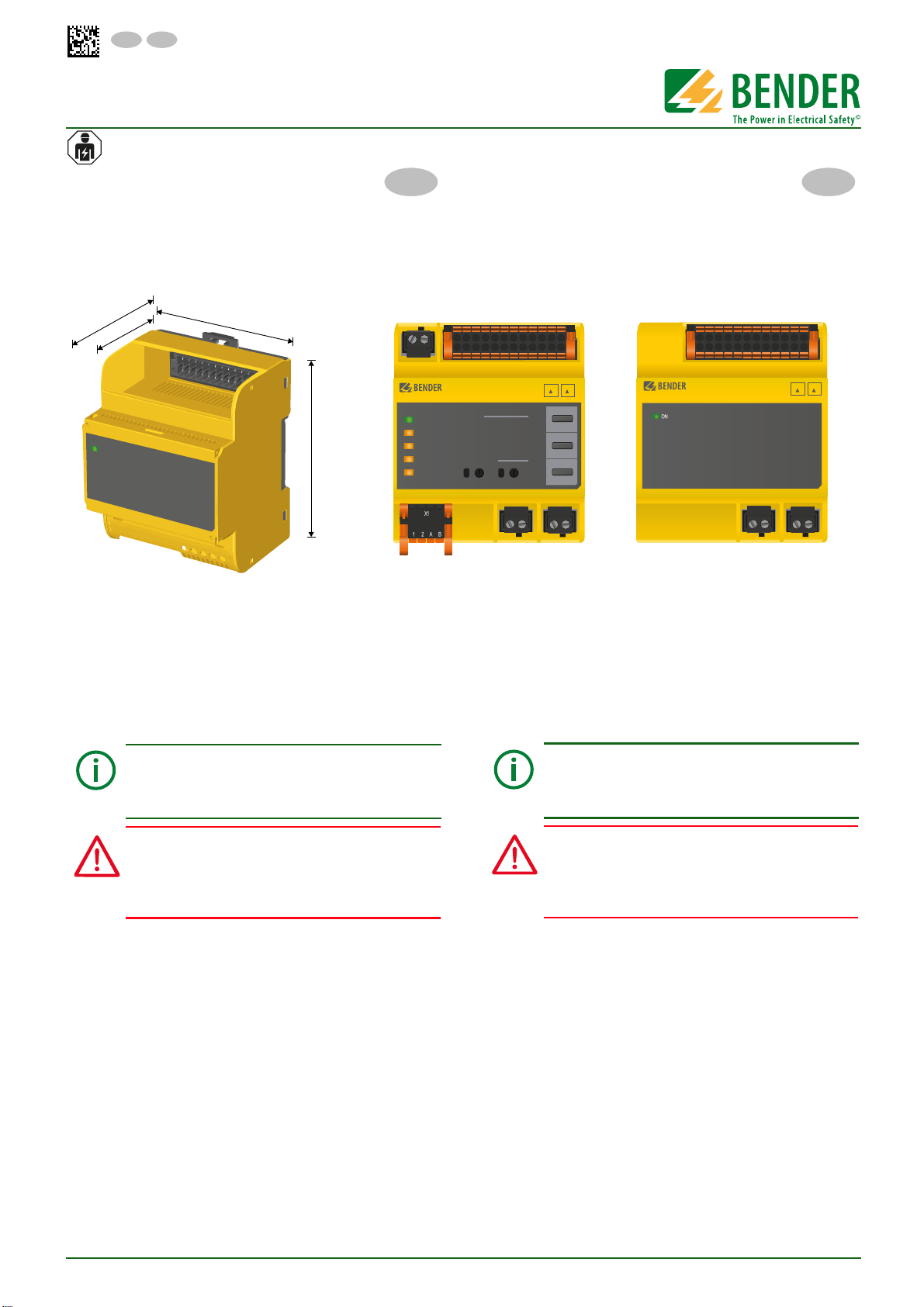
DIN rail mounting
1. Fix one of the mounting clips supplied, either manually or by
means of a tool, into position as shown in the illustration below.
2. EDS…-S-CN only: Attach the BB bus to the device. To do this,
refer to the BB bus mounting instructions supplied.
3. Snap the EDS… device onto the DIN rail.
Screw mounting
1. Fix the two mounting clips supplied, either manually or by
means of a tool, into position as shown in the illustration
below.
2. Drill the mounting holes for the M4 thread according to the
dimensioned drilling template.
3. Then fix the EDS… using two (2) M4 screws.
Network configuration, mains voltage, mains frequen-
cy, leakage capacitance and test current influence the
responsiveness of the EDS system. Please refer to the re-
sponse sensitivity curve in the manual.
Risk of electric shock!
Make sure the system is de-energized before installing
the device. Otherwise there is a risk of electric shock. Fur-
thermore, the electrical installation may be damaged
and the device may be destroyed beyond repair.
DANGER
绝缘故障定位仪
这本快速入门指南适用于下列型号:EDS440/441-L-CN,
W-L-CN, -S-CN, W-S-CN, EDS441-LAB-4-CN 和 W-CN 设备。
这本快速入门手册不能替代操作手册。
你可以在我们的主页 www.bender.de/manuals 上找到操作手
册。
使用目的
绝缘故障定位仪 EDS44… 能够定位不接地直流、交流和三相交
流系统中的绝缘故障 (IT 系统 )。
通过故障定位电流发射器 (PGH),可以根绝 PGH 的型号来监视
AC 0…1000 V 范围内的交流和三相交流网络以及 DC 0…1500
V 范围内直流网络。可以显示 42 Hz…1 kHz, 100 mA…20 A 范
围内的交流剩余电流 (EDS440) 或 50/60 Hz, 100 mA…2 A
(EDS441) 范围内的交流剩余电流 。
DIN 导轨安装
1. 提供一组安装夹, 无论是手动或通过工具的手段,如下
图所示安装到合适的位置。
2. 仅 EDS…-S-CN:把 BB 总线接入设备。请参考 BB 总线安
装介绍。
3. 把 EDS… 设备安装到 DIN 导轨上。
螺丝安装
1. 如下图所示,手动或者使用工具安装 2 个配套的安装夹
把设备安装到合适的位置。
2. 根据尺寸的钻模板,为 M4 螺丝钻安装孔。
3. 然后使用 2 个 M4 螺丝固定 EDS… 。
网络配置、电源电压、电源频率、泄露电容和测试
电流会影响 EDS 系统的响应。请参考手册中的响应
灵敏度曲线。
电击危险 !
在安装设备之前,请确保系统是断电的。否则可能
会发生电击。此外,电气装置可能会损坏并且设备
可能会被损坏无法修复。
ISOSCAN®
EDS440
I
L
I
n
l
k
1 2 3 4 5 6 7 8 9 10 11 12
13 14 23 24
ON
l1 l2 l3 l4 l5 l6 l7 l8 l9 l10 l11 l12
k1 k2 k3 k4 k5 k6 k7 k8 k9 k10 k11 k12
48,5 mm
62,5 mm
71,7 mm
93 mm
ON
I
L
I
n
ISOSCAN®
EDS440
7
6
5
3
8
4
2
0
1
6
5
3
4
2
0
1
9
8
TEST
MUTE
RESET
ALARM
ALARM
ON
COM
SERVICE
CHANNELS
SLAVE ADDRESS
12
11109
87
123456
1
7
I
∆L
I
∆n
l1 l2 l3 l4 l5 l6 l7 l8 l9 l10 l11 l12
k1 k2 k3 k4 k5 k6 k7 k8 k9 k10 k11 k12
ll
A1/+ A2/-
l
k
1 2 3 4 5 6 7 8 9 10 11 12
13 14 23 24X1
EDS440/441(W)-S-CNEDS440/441(W)-L-CN/EDS441-LAB-4(W)-CN
危险
EDS44...L-CN/EDS44...S-CN
EDS440-441_D00201_01_Q_CNEN/11.2016
CN EN

2EDS440-441_D00201_01_Q_CNEN/11.2016
EDS44...L-CN/EDS44...S-CN
Connection
Connect the device according to the wiring diagram. Also refer to
the technical data. After connecting the device, install the upper
and lower terminal cover.
Risk of electric shock!
Make sure the system is de-energized before installing
the device. Otherwise there is a risk of electric shock. Fur-
thermore, the electrical installation may be damaged
and the device may be destroyed beyond repair.
Provide line protection!
According to DIN VDE 0100-430, a line protection shall
be provided for the supply voltage.
For UL applications:
Use 60/75 °C copper wires only! For UL and CSA applica-
tions, the supply voltage must be protected via 5 A fuses.
The maximum voltage of the monitored network must
not be greater than the rated insulation voltage of all
components used. Select cables and cable lengths ac-
cording to the technical data.
DANGER
CAUTION
连接
参考接线图连接设备。同时也请参考技术参数。
在连接设备之后,安装上下盖板。
电击危险 !
在安装设备之前,请确保系统是断电的。否则可能
会发生电击。此外,电气装置可能会损坏并且设备
可能会被损坏无法修复。
提供线路保护 !
符合标准 DIN VDE 0100-430,线路保护将用于电源
电压。
对于 UL 应用:
仅使用 60/75 °C 的铜线 ! 对于 UL 和 CSA 应用,
电源电压必须通过 5A 的保险丝进行保护。
被监视网络的最大电压不得大于所有使用中组件
的额定绝缘电压。根据技术参数选择电缆和电缆长
度。
螺丝安装 / Screw mounting 导轨安装 /DIN rail mounting
99,0 mm
71,7 mm
危险
警告
3
EDS440-441_D00201_01_Q_CNEN/11.2016
EDS44...L-CN/EDS44...S-CN
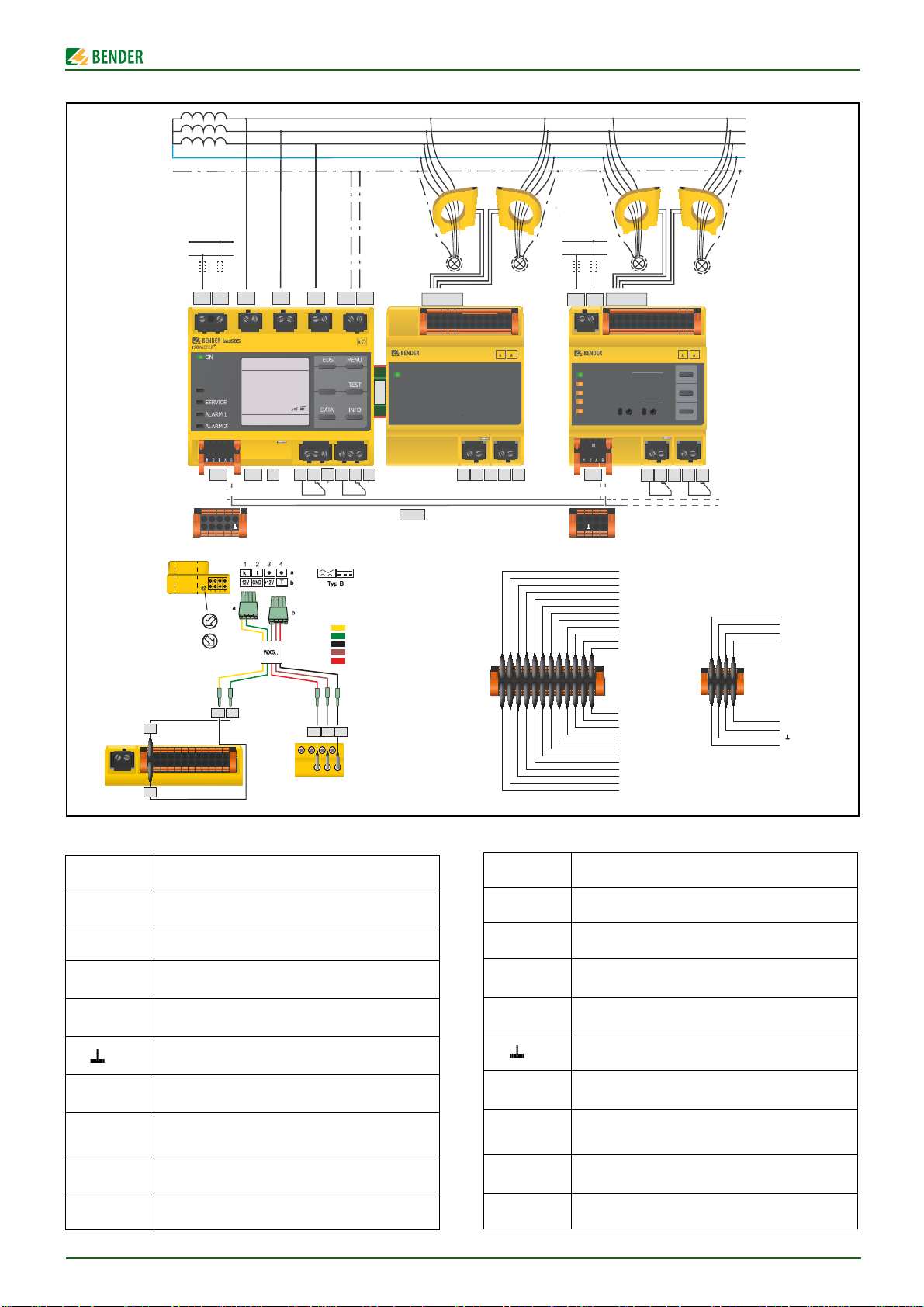
Wiring diagram
Legend to wiring diagram
Terminal Connections
A1/+, A2/- Connection to supply voltage Us
k1-12/l1-12 Measuring current transformer connection
I1, I2 (X1) Configurable digital inputs
(e.g. Test, Reset)
A, B (X1) Serial interface RS-485 (BS bus),
Input or output interface (assignment is arbitrary)
(X1) Reference potential ground
M+ (X1) Configurable digital current output
0 or 20 mA, e.g. for PLC current input
13-14 /
23-24
Alarm relay
Different functions can be selected
RTerminating resistor to terminate the
RS-485 interface (BS bus)
BB-Bus Communications interface for Bender products
接线图
接线图例
端子 连接
A1/+, A2/- 连接到电源电压
U
s
k1-12/l1-12 连接测量电流互感器
I1, I2 (X1) 可配置数字输入
( 例如,测试,重置 )
A, B (X1) 串行接口 RS-485 (BS 总线 )
输入或输出接口 ( 任意分配 )
(X1) 可配置的模拟输出
( 例如:测量仪器 )
M+ (X1) 可配置的数字电流输出
0 或 20 mA, 例如,用于 PLC 电流输入
13-14 /
23-24
报警继电器
可选不同的功能
R终端电阻器来终止
RS-485 接口 (BS 总线 )
BB 总线 Bender 产品的通讯接口
IT-System
O
K
R(an)
4 0 kΩ/10kΩ
O
K
>20
MΩ>20
MΩ
PGH ON
L1
L2
L3
N
PE
US
Un
U
X1
ISOSCAN®
EDS440
7
6
5
3
4
2
0
1
6
5
3
4
2
0
1
9
ON
I LI n
l
k1 2 3 4 5 6 7 8 9 10 11 12
13 14 23 24
A1/+ A2/- L1/+ L2 L3/- KE E
11RETH 12 14 21 22 24
I1 I2 I3 A B
Q1
+
Q2 M+
X1
k1-12/l1-12
ISOSCAN®
EDS440
7
6
5
3
4
2
0
1
6
5
3
4
2
0
1
9
I L
I n
S
ll
I1 I2 AB
M+ BA
X1
A B A B
X1
X1
BB-Bus
BS-Bus
l
k1 2 3 4 5 6 7 8 9 10 11 12A1/+ A2/-
13 14 23 24X1
13 14 2423
R
A1/+ A2/- k1-12/l1-12
X1 13 14 2423
R
L1 L2 L3 L4 L5 L6 L7 L8 L9 L10 L11 L12
K1 K2 K3 K4 K5 K6 K7 K8 K9 K10 K11 K12
L1 L2 L3 L4 L5 L6 L7 L8 L9 L10 L11 L12
K1 K2 K3 K4 K5 K6 K7 K8 K9 K10 K11 K12
A1 A2
2
6
9
8
TEST
MUTE
RESET
ALARM
ALARM
ON
COM
SERVICE
CHANNELS
SLAVE ADDRESS
12
11109
87
123456
1
7
IL
In
l1
l2
l3
l4
l5
l6
l7
l8
l9
l10
l11
l12
k12
k11
k10
k9
k8
k7
k6
k5
k4
k3
k2
k1
I1
I2
A
B
M+
B
A
k1-12/l1-12 X1
W...AB b
a
CT1
A1 A2
+12V GND -12V
A1 A1 A2A2
AN420
EDS441-LAB-4
Nicht für EDS441
Not for EDS441
Ne concerne pas l´EDS441
No para el EDS441
WXS… :
k:
l:
-12 V:
GND:
+12 V:
l1
k1
k1
l1 +12V -12VGND
I(Δn) ≤ 500 mA
I(Δn) > 500 mA

4EDS440-441_D00201_01_Q_CNEN/11.2016
EDS44...L-CN/EDS44...S-CN
Commissioning of the device
Prior to initial commissioning
Make sure that…
•The PE line is not conducted through a measuring current
tansformer.
•There are no interfering magnetic fields located near the cur-
rent transformer.
•The maximum permissible cable length is in compliance to the
measuring current transformers.
•
The beginning and end of the BS bus is terminated, i.e. R (= ON).
•The permissible length of the BS bus line (max. 1200 m) and
the number of EDS… devices in the bus system (21) is not
exceeded (max. 252 measuring channels).
•An address is not assigned twice.
Initial commissioning
•Connect the device and the current transformer.
•Connect the devices to each other via the BS bus (EDS…-L-CN)
or BB-Bus (EDS…-S-CN).
•Switch the supply voltage on. The LED "ON" flashes during
power up until the device is ready for operation.
•Set the appropriate BS bus address.
•EDS…-L-CN: by using the EDS rotary switches. The selected
channel address is indicated by a lighting LED.
•Eliminate all possible displayed insulation and device faults via
the ISOMETER® or the EDS…-L-CN RESET button.
•Ensure the EDS… is properly connected.
•A transformer connection test is carried out every 10 minutes.
During each test, the "ON" LED flashes.
To commission the ISOMETER® and the system from the EDS…
and ISOMETER®, refer to the ISOMETER® documentation.
Operation
The EDS…-S can only be operated via the ISOMETER®.
The EDS…-L-CN is operated via the following three keys and oth-
erwise via the ISOMETER®.
Alarm and its effect
General sequence of an alarm message
•The
ISOMETER®
display indicates a fault and, if applicable, a
measured value or channel.
EDS…-L only:
•The corresponding LEDs light or flash.
•The buzzer sounds intermittently if activated.
•Assigned alarm relays will switch (EDS…-L-CN/-S-CN).
•Assigned digital outputs will switch.
•An alarm message is then sent over the BB bus (EDS…-S-CN)
or BS bus (EDS…-L-CN).
Alarm messages (EDS…-S-CN)
EDS…-S-CN alarm messages are reported
via the relays and are
displayed via
the
ISOMETER®.
TEST Initiate self test
RESET Reset fault memory
MUTE Disable buzzer for the current alarm message
设备的启动
首次启动之前
确保 …
•PE 线没有通过测量电流互感器传导。
•在电流互感器周围没有干扰磁场。
•最大允许电缆长度符合测量电流互感器的长度的要求。
•在 BS 总线的首尾两端终止,例如: R (= ON)。
•在总线系统 (21) 中,BS 总线电缆所允许的长度 ( 最大
1200 m) 以及 EDS… 设备的数量不能超过 ( 最大 252 测量
通道 )。
•个地址不能被分配 2 次。
首次启动
•连接设备和电流互感器。
•通过 BS 总线 (EDS…-L-CN) 或 BB 总线 (EDS…-S-CN) 互相连
接设备。
•打开电源电压。LED 灯 "ON" 在通电后闪烁,直到设备准备就
绪。
•设置适合的 BS 总线地址。
•EDS…-L-CN: 通过使用 EDS 旋转开关。 通过亮着的 LED 灯指
示选择的通道地址。
•通过 ISOMETER® 或 EDS…-L-CN 重置按钮消除所有可能显示
的绝缘和设备故障。
•确保 EDS… 是正确连接的。
•互感器连接测试每 10 分钟执行一次。在每个测试期间,
"ON" LED 灯闪烁。
参考 ISOMETER® 手册,启动 ISOMETER® 和来自 EDS… 和
ISOMETER® 的系统。
工作
EDS…-S 只能通过 ISOMETER® 进行操作。
EDS…-L-CN 可以通过下列三个按键以及 ISOMETER® 进行操作。
报警和它的作用
报警信息的通用排序
•如果需要,
ISOMETER®
显示故障,测量值或通道。
仅用于 EDS…-L:
•相应的 LED 灯亮或者闪烁。
•如果启动,蜂鸣器的声音是断断续续的。
•分配的报警继电器动作 (EDS…-L-CN/-S-CN)。
•分配的数字输出动作。
•然后报警信息通过 BB 总线 (EDS…-S-CN) 或 BS 总线 (EDS…-
L-CN) 发送。
报警信息 (EDS…-S-CN)
EDS…-S-CN 报警系统通过继电器报告
并且通过
ISOMETER® 显
示。
TEST 开始自检
RESET 重置故障记忆
MUTE 禁用用于当前报警消息的蜂鸣器

5
EDS440-441_D00201_01_Q_CNEN/11.2016
EDS44...L-CN/EDS44...S-CN
报警信息 (EDS…-L)
•绝缘故障:LED „ALARM IΔL“ ( 主报警 ) 和测量通道 LED 灯
所对应的灯同时亮起,就可找到对应的错误。
•如果超过剩余电流阈值:LED „ALARM IΔn“ 和测量通道
LED 灯所对应的灯同时亮起,就可找到对应的错误。
•设备故障,互感器连接故障:
"SERVICE" LED 灯亮。此外,相应通道的 LED 灯闪烁。
•报警信息:受影响的测量通道的通道 LED 闪烁。
•如果几个错误信息同时输出,单独信息可以通过观察报警
或服务 LED 灯或闪烁的通道 LED 来区分。
声音报警 ( 蜂鸣器 ) 可以被分配用于下列故障信息并且用过
MUTE( 静音 ) 按钮停用。
Alarm IΔL、Alarm IΔn、设备故障、连接故障、普通报警、主
动绝缘故障定位。
重置报警信息 (Reset)
要求:重置故障记忆,同时故障不再存在。
执行 RESET 来重置报警。 有 3 中可能性:
•按下 EDS
…
-L-CN 的 RESET 的按钮持续至少 1 秒。
•按下外部重置按钮连接到 EDS
…
•在 BS 总线或 BB 总线上,从
ISOMETER®
发送 RESET 命令。
按下 ISOMETER® 上的 "ESC" 按钮
退出当前告警信息的显示。
Alarm messages (EDS…-L)
•Insulation fault: Both the LED „ALARM IΔL“ (main alarm) and
the measuring channel LED, corresponding to where the error
was found, light.
•If the residual current threshold is exceeded: Both the LED
„ALARM IΔn“ and the measuring channel LED, corresponding
to where the error was found, light.
•Device fault, transformer connection fault:
The "SERVICE" LED lights. In addition, the corresponding chan-
nel LED flashes.
•Alarm messages: The channel LED of the affected measuring
channel flashes.
•If several error messages are simultaneously output, individual
messages can be distinguished by observing which alarm or
service LED lights or flashes with which channel LED.
The audible alarm (buzzer) can be assigned the following error
messages and deactivated with the MUTE button:
Alarm IΔL, Alarm IΔn, device fault, connection fault, common
alarm, active insulation fault location.
Reset alarm messages (Reset)
Requirement: The fault memory has been activated and the error
is no longer active.
Execute a RESET to reset the alarms. There are 3 possibilities:
•Press the EDS
…
-L-CN RESET button for at least 1s.
•Press an external reset button connected to the EDS
…
•Transmit a RESET command from an
ISOMETER®
over the BS
bus or BB bus.
Press the "ESC" button on the ISOMETER®
to exit the display of the
current alarm message.

6EDS440-441_D00201_01_Q_CNEN/11.2016
EDS44...L-CN/EDS44...S-CN
Technical data
( )* = factory setting
Insulation co-ordination
Rated insulation voltage (IEC 60664-1 ..................................................................................................AC 250 V
Rated impulse voltage (IEC 60664-1)............................................................................................................4 kV
Overvoltage category..........................................................................................................................................III
Pollution degree...................................................................................................................................................2
Protective separation (reinforced insulation) between .......................................................................................
...................................................................................................................(A1,A2)-(13,14)-(23,24)-(X1,X2,X3)
Voltage test acc. to IEC 61010-1..................................................................................................................2.2 kV
Supply voltage
Supply voltage range Us.........................................................................................................AC/DC 24…240 V
Tolerance of Us.............................................................................................................................. -20…+15 %
Frequency range of Us.........................................................................................................DC, 50…400 Hz 1) 2)
Response values
Insulation fault location response value (I∆L) .......................................................EDS440: 2…10 mA (5 mA)*
........................................................................................................................... EDS441: 0.2…1 mA (0.5 mA)*
Response uncertainty (I∆L) .......................................................................................EDS440: ±30 %, ±2 mA 3)
................................................................................................................................EDS441: ±30 %, ±0.2 mA 3)
Residual current measurement response value (I∆n) ....................................EDS440: 100 mA…10 A (10 A)*
............................................................................................................................. EDS441: 100 mA…1 A (1 A)*
Response uncertainty (I∆n) EDS44… (42…60 Hz)..................................................................................±5 %
Response uncertainty (I∆n) EDS440 (61…1000 Hz).........................................................................-20…0 %
Measuring circuit
Nominal system voltage UnEDS440 ..........................................................................see test currentgenerator
.........................................................................................................................(e.g. ISOMETER® iso685-D-P-CN)
Nominal system voltage UnEDS441 ............................................................... AC 20…276 V, DC 20…308 V
Measuring ranges
Rated frequency range..........................................................................................................DC, 42…1000 Hz4)
Insulation fault location measurement range (IΔL) ..............................................................................................
...................................................................................................EDS440: 1.5…25 mA (50 mA in DC networks)
........................................................................................................................................... EDS441: 0.15…5 mA
Residual current measurement range (IΔn) ..................................................................EDS440: 100mA…20 A
..........................................................................................................................................EDS441: 100mA…2 A
Interfaces
Interface/protocol ...............................................................................................................................RS-485/BS
Switching elements
Switching elements ........................................................................................................ 2 changeover contacts
Operating mode ................................................................................................ N/C operation / N/O operation*
Function contacts 13,14/23,24.............................................................None, Alarm IΔL, Alarm IΔn, device fault,
......................................................................................................transformer connection fault, common alarm
Electrical endurance under rated operating conditions................................................................. 30,000 cycles
Rated operating voltage ......................................................................................................................... 250 VAC
Rated operational current.................................................................................................................................7 A
Rated insulation voltage ................................................................................................................................ 4 kV
Max. switching capacity ........................................................................................................... 300 W / 2770 VA
Max. switching voltage............................................................................................................ 30 VDC / 277 VAC
Other
EMC.................................................................................................................................................IEC 61326-2-4
Degree of protection, built-in components (DIN EN 60529) ....................................................................... IP40
Degree of protection, terminals (DIN EN 60529) ......................................................................................... IP20
1) For frequencies >60 Hz, the k1…12, l1…12, M+, GND, I1 and I2 connections must be safe to touch. Min.
acc. to the overvoltage category 2 (300 V).
2) only 50/60 Hz are permitted for UL applications.
3) Impact of a residual current >100 mA results in a greater response uncertainty.
4) The IΔn function of the EDS441… is suitable for 50/60 Hz only.
Service
Service hotline: 0700-BenderHelp (Phone and fax)
Carl-Benz-Straße 8 • 35305 Gruenberg • Germany
Tel: +49 6401 807-760 • Fax: +49 6401 807-629
技术参数
( )* = 出厂设置
绝缘协调性
额定电压 (IEC 60664-1 .............................. AC 250 V
额定脉冲电压 (IEC 60664-1) ............................. 4 kV
过电压分类 ............................................. III
污染等级 ................................................. 2
保护隔离 ( 增强绝缘 ) 介于 ...................................
......................... (A1,A2)-(13,14)-(23,24)-(X1,X2,X3)
电压测试符合 IEC 61010-1 ............................. 2.2 kV
电源电压
电源电压范围
U
s............................. AC/DC 24…240 V
公差
U
s.......................................... -20…+15 %
频率范围
U
s...............................DC, 50…400 Hz 1) 2)
响应值
绝缘故障定位响应值 (
I
∆L) .......... EDS440: 2…10 mA (5 mA)*
................................ EDS441: 0.2…1 mA (0.5 mA)*
相对不确定性 (
I
∆L) ................ EDS440: ±30 %, ±2 mA 3)
................................. EDS441: ±30 %, ±0.2 mA 3)
剩余电流测量响应值 (
I
∆n) ...... EDS440: 100 mA…10 A (10 A)*
................................. EDS441: 100 mA…1 A (1 A)*
相对不确定性 (
I
∆n) EDS44… (42…60 Hz) ................ ±5 %
相对不确定性 (
I
∆n) EDS440 (61…1000 Hz) ............ -20…0 %
测量电路
标称系统电压
U
n EDS440.................... 参考测试电流发射器
............................ ( 例如:ISOMETER® iso685-D-P-CN)
标称系统电压
U
n EDS441 .......... AC 20…276 V, DC 20…308 V
测量范围
额定频率范围 ............................... DC, 42…1000 Hz4)
绝缘故障定位测量范围 (
I
ΔL)
.................... EDS440: 1.5…25 mA ( 在直流电路中 50 mA)
......................................... EDS441: 0.15…5 mA
剩余电流测量范围 (
I
Δn) ................ EDS440: 100mA…20 A
......................................... EDS441: 100mA…2 A
接口
接口 / 协议 ........................................ RS-485/BS
开关元件
开关元件 ...................................... 2 组转换触点
工作模式 ...................................... 常闭 / 常开 *
功能触点 13,14/23,24 ...无 , Alarm
I
ΔL, Alarm
I
Δn, 设备故障 ,
................................... 互感器连接故障 , 普通报警
额定工况下的电气耐久性 ........................ 30,000 周期
额定工作电压 ....................................... 250 VAC
额定工作电流 ............................................ 7 A
额定绝缘电压 .......................................... 4 kV
最大开关容量 ................................ 300 W / 2770 VA
最大开关电压 ............................... 30 VDC / 277 VAC
其它
EMC ........................................... IEC 61326-2-4
防护等级、内置元件 (DIN EN 60529) .................... IP40
防护等级、端子 (DIN EN 60529) ........................ IP20
1) 当频率 >60 Hz,k1…12, l1…12, M+, GND, I1 和 I2 的连接必须
是安全接触的。至少符合过电压等级 2 (300 V)。
2) 仅 50/60 Hz 允许应用于 UL。
3) 剩余电流 >100 mA 的影响会导致一个更大的相对不确定性。
4)EDS441…
I
Δn 的功能仅适合 50/60 Hz。
服务
服务热线:0700-BenderHelp ( 电话和传真 )
Carl-Benz-Straße 8 • 35305 Gruenberg • Germany
电话:+49 6401 807-760 • 传真:+49 6401 807-629
电子邮件:[email protected] • www.bender.de

7
EDS440-441_D00201_01_Q_CNEN/11.2016
EDS44...L-CN/EDS44...S-CN
8EDS440-441_D00201_01_Q_CNEN/11.2016
EDS44...L-CN/EDS44...S-CN
保留版权。
复制和转载
必须由出版商认可。
修改受管制 !
©Bender GmbH & Co. KG
All rights reserved.
Reprinting only with permission
of the publisher.
Subject to change!
©Bender GmbH & Co. KG
服务 / Service
服务热线 /Hotline: 0700-BenderHelp (Telephone and Fax)
Carl-Benz-Straße 8 • 35305 Gruenberg • Germany
电话 /Tel.: +49 6401-807-760 • 传真 /Fax: +49 6401 807-629
电子邮件 /E-mail: info@bender-service.com • www.bender.de
Bender GmbH & Co. KG
Postfach 1161 • 35301 Grünberg • Germany
Londorfer Str. 65 • 35305 Grünberg • Germany
电话 /Tel.: +49 6401-807-0 • 传真 /Fax: +49 6401 807-259
电子邮件 /E-mail: [email protected] • www.bender.de
文件 /Documentation:
This manual suits for next models
9
Table of contents
Other Bender Relay manuals

Bender
Bender LINETRAXX VMD461 User manual

Bender
Bender EDS440 Instruction manual

Bender
Bender VME421H User manual

Bender
Bender LINETRAXX VMD258 User manual

Bender
Bender UMS420 User manual

Bender
Bender RCM470LY User manual

Bender
Bender CMD420 User manual

Bender
Bender cme420 User manual

Bender
Bender cme420 Manual

Bender
Bender IOM441-S User manual


Popular Relay manuals by other brands


GRUP ARGE
GRUP ARGE RKR NT-S12 user manual

System Sensor
System Sensor i3 Series Installation and maintenance instructions

ARC SUPPRESION TECHNOLOGIES
ARC SUPPRESION TECHNOLOGIES NOsparc MGXDC1F250 user manual

Wöhner
Wöhner QUADRON 185Power quick start guide

Tyco
Tyco HVR800 manual

Circutor
Circutor RGU-100A instruction manual


