Bender UMS420 User manual

1
Spannungsrelais für
Umschaltmodule
Bestimmungsgemäße Verwendung
Das Spannungsrelais UMS420 dient zur unterbrechungsfreien
Versorgung des Steuergerätes PRC487-29 (24 V) in OP-Leuchten-
Umschalteinrichtungen.
Aufgaben des UMS420
•Unterbrechungsfreie Versorgung des Steuergerätes
PRC487-29 (24 V) aus Leitung 1 (AC 24 V) und Leitung 2
(DC 24 V).
•Bereitschaft der Leitung 1 und 2 anzeigen (LED).
•Ausfall der Leitung 2 über Relaiskontakt melden.
Ein Transformator im Eingang der Leitung 1 gewährleistet eine
Trennung von Leitung 1 und Leitung 2.
Sicherheitshinweise allgemein
Montage, Anschluss und Inbetriebnahme nur durch Elektrofach-
kraft!
Beachten Sie unbedingt:
•die bestehenden Sicherheitsvorschriften und
•das beiliegende Blatt „Wichtige sicherheitstechnische Hin-
weise für Bender-Produkte“.
Bedienelemente
LED 1 Signalisiert Betriebsbereitschaft der Leitung 1
LED 2 Signalisiert Betriebsbereitschaft der Leitung 2
UMS 420
ON
12
Voltage relay for
switchover modules
Intended Use
UMS420 is a voltage relay suitable for the uninterrupted power
supply of PRC487-29 control devices in switchover modules for
operating theatre lamps.
Characteristics
•Uninterrupted power supply of PRC487-29 control device
(24 V) from line 1 (AC 24 V) and line 2 (DC 24 V).
•LED indication for line 1 and line 2 ready for operation.
•Signalling failure of line 2 via alarm contact.
Isolation between line 1 and line 2 is guaranteed by means of a
transformer in the input of line 1.
Safety Information
Installation, connection and commissioning of electrical equip-
ment shall only be carried out by skilled persons:
Particular attention shall be paid to:
•current safety regulations and
•the enclosed sheet "Important Safety Instructions for Ben-
der Products".
Operating elements
LED 1 Signals that line 1 is ready for operation
LED 2 Signals that line 2 is ready for operation
UMS420
TBP204016deen / 03.2012
Deutsch English

2TBP204016deen / 03.2012
UMS420
Montage und Anschluss
Montage
•Montage auf Hutschiene:
Rasten Sie die rückseitigen Montageclip des Geräts auf der
Hutschiene so ein, dass ein sicherer und fester Sitz gewähr-
leistet ist.
•Schraub-Befestigung:
Bringen Sie die rückseitigen Montageclips (2. Montage-
clip erforderlich, siehe Bestellinformation) mittels Werk-
zeug in eine über das Gehäuse hinaus ragende Position.
Befestigen Sie danach das Gerät mit zwei M4-Schrauben.
Maßbild
Alle Maße in mm
Stellen Sie vor Einbau des Gerätes und vor Arbei-
ten an den Anschlüssen des Gerätes sicher, dass
die Anlage spannungsfrei ist.
Wird dies nicht beachtet, so besteht für das Perso-
nal die Gefahr eines elektrischen Schlages.
Außerdem drohen Sachschäden an der elektri-
schen Anlage und die Zerstörung des Gerätes.
90 mm
45
67,5
36 mm
31,1
47,5
70,5
100 mm
116 mm
Zubehör/
Accessory
Installation and connection
Installation
•DIN rail mounting:
Snap the rear mounting clip of the device into place in
such a way that a safe and tight fit is ensured.
•Screw fixing:
Use a tool to move the rear mounting clip (another mount-
ing clip required, see ordering details) into a position that
it projects beyond the enclosure. Then fix the device using
two M4 screws.
Dimension diagram
All dimensions in mm
Prior to installation and before any work is carried
out on the connecting cables, make sure that the
mains power is disconnected.
Failure to comply with this safety information
may cause electric shock to personnel.
Substantial damages to the electrical installation
and destruction of the device may occur.

3
TBP204016deen / 03.2012
UMS420
Anschluss
Legende zum Anschlussschaltbild
Normen
•DIN VDE 0100-710 (VDE 0100 Teil 710):2002-11
•ÖVE/ÖNORM E8007:2007-12-01
•IEC 60364-7-710:2002-11
Technische Daten
Isolationskoordination nach IEC 60664-1
Bemessungsspannung ..........................................................................................................AC 50 V
Bemessungs-Stoßspannung/Verschmutzungsgrad........................................................... 800 V/3
Spannungsbereiche
Leitung 1:
Versorgungsspannung US...........................................................................45…65 Hz, 20 ... 28 V
Eigenverbrauch ..................................................................................................................... ≤ 5 VA
Leitung 2:
Versorgungsspannung US...........................................................................................DC 20 ... 28 V
Eigenverbrauch ..................................................................................................................... ≤ 2 VA
Ausgang IN3, GND3
Schaltelemente.................................................................................................................1 Schließer
Arbeitsweise .....................................................................................................................Ruhestrom
Elektrische Lebensdauer bei Bemessungsbedingungen ..................................10.000 Schaltspiele
1L1, 1L2 Leitung 1, AC 24 V, 45…65 Hz
2L+, 2L- Leitung 2, DC 24 V
A4+, A3- Versorgung des PRC487-29 (Leitung 3),
DC 24 V, ca. 80 mA
IN3, GND3 Meldung „Ausfall Leitung 2“, zum Anschluss an
die Kontakte IN3, GND3 des PRC487-29
UMS 420
ON
12
1L1 1L2 2L+ 2L-
A4+ A3- IN3
GND3
Leitung 1
Line 1
AC 24 V
Leitung 2
Line 2
DC 24 V
Versorgung PRC487-29
upply PRC487-29
zum PRC487-29, Kontakte IN3, GND3
to the PRC487-29, terminals IN3, GND3
Connection
Legend to wiring diagram
Standards
•DIN VDE 0100-710 (VDE 0100 Part 710):2002-11
•ÖVE/ÖNORM E8007:2007-12-01
•IEC 60364-7-710:2002-11
Technical data
Insulation coordination according to IEC 60664-1
Rated voltage........................................................................................................................ AC 50 V
Rated impulse voltage/pollution degree..............................................................................800 V/3
Voltage ranges
Line 1:
Supply voltage US........................................................................................ 45…65 Hz, 20 ... 28 V
Power consumption ............................................................................................................. ≤ 5 VA
Line 2:
Supply voltage US........................................................................................................ DC 20 ... 28 V
Power consumption ............................................................................................................. ≤ 2 VA
Output IN3, GND3
Switching elements....................................................................................................... 1 NO contact
Operation mode ..........................................................................................................N/C operation
Electrical endurance during rated operating conditions.................... 10.000 switching operations
1L1, 1L2 Line 1, AC 24 V, 45…65 Hz
2L+, 2L- Line 2, DC 24 V
A4+, A3- Power supply of the PRC487-29 (line 3),
DC 24 V, approx. 80 mA
IN3, GND3 Signals "Failure line 2", to be connected to the
contacts IN3, GND3 of the PRC487-29

4TBP204016deen / 03.2012
UMS420
Londorfer Str. 65 •35305 Grünberg • Germany Fax: +49 6401 807-259 Web: http://www.bender-de.com
Postfach 1161 •35301 Grünberg • Germany
Alle Rechte vorbehalten.
Nachdruck und Vervielfältigung
nur mit Genehmigung des Herausgebers.
Änderungen vorbehalten!
©Bender GmbH & Co. KG
All rights reserved.
Reprinting and duplicating
only with permission of the publisher.
Subject to change!
©Bender GmbH & Co. KG
Kontaktdaten nach IEC 60947-5-1
Gebrauchskategorie .................................................................................. AC-13 AC-14 DC-12
Bemessungsbetriebsspannung .................................................................. 50 V 50 V 50 V
Bemessungsbetriebsstrom .......................................................................... 2 A 0,5 A 0,2 A
Minimale Kontaktbelastbarkeit ................................................................10 mA bei AC / DC > 5 V
Ausgang A4+, A3-
Ausgangsspannung..................................................................................................... DC 18 ... 35 V
Allgemeine Daten
EMV Störfestigkeit ............................................................................................. nach EN 61000-6-2
EMV Störaussendung ...................................................................................... nach IEN 61000-6-4
Schockfestigkeit IEC60068-2-27 (Gerät in Betrieb) .......................................................15 g/11 ms
Dauerschocken IEC60068-2-29 (Transport).....................................................................40 g/6 ms
Schwingungsbeanspruchung IEC 60068-2-6 (Gerät in Betrieb).........................1 g / 10 ... 150 Hz
Schwingungsbeanspruchung IEC 60068-2-6 (Transport)...................................2 g / 10 ... 150 Hz
Umgebungstemperatur (bei Betrieb) .................................................................... -10 °C ... +55 °C
Umgebungstemperatur (bei Lagerung) ................................................................ -40 °C ... +70 °C
Klimaklasse nach DIN IEC60721-3-3 ...........................................................................................3K5
Betriebsart......................................................................................................................Dauerbetrieb
Einbaulage .............................................................................................................................beliebig
Anschlussart.............................................................................................................Reihenklemmen
Anzugsdrehmoment ........................................................................0,5 ... 0,6 Nm (4,3 ... 5,3 lb-in)
Anschlussvermögen starr / flexibel............................................................0,2 ... 4 / 0,2 ... 2,5 mm2
Anschlussvermögen flexibel mit Aderendhülse, ohne/mit Kunststoffhülse.........0,25 ... 2,5 mm2
Leitergrößen (AWG).................................................................................................................24-12
Schutzart Einbauten (DIN EN 60529 (VDE 0470):2000-09) ......................................................IP30
Schutzart Klemmen (DIN EN 60529 (VDE 0470):2000-09).......................................................IP20
Schraubbefestigung.................................................................................................................2 x M4
Schnellbefestigung auf Hutprofilschiene.......................................................................... IEC 60715
Entflammbarkeitsklasse ...................................................................................................... UL94V-0
Gewicht ca. ................................................................................................................................200 g
Bestellangaben
Typ / Type UsArt. No.
UMS420 UN1: AC 24 V 50 Hz
UN2: DC 24 V
IN: max. DC 200 mA
B92047018
Contact data acc. to IEC 60947-5-1
Utilisation category ...................................................................................AC-13 AC-14 DC-12
Rated operational voltage .......................................................................... 50 V 50 V 50 V
Rated operational current ........................................................................... 2 A 0.5 A 0.2 A
Minimum contact rating ............................................................................10 mA at AC / DC > 5 V
Output A4+, A3-
Output voltage............................................................................................................. DC 18 ... 35 V
General data
EMC immunity.................................................................................................acc. to EN 61000-6-2
EMC emission .................................................................................................acc. to EN 61000-6-4
Shock resistance IEC60068-2-27 (device in operation)................................................. 15 g/11 ms
Bump IEC60068-2-29 (during transport) ....................................................................... 40 g/6 ms
Vibration strain IEC 60068-2-6 (device in operation) .........................................1 g / 10 ... 150 Hz
Vibration strain IEC 60068-2-6 (during transport) .............................................2 g / 10 ... 150 Hz
Ambient temperature (during operation) ............................................................ -10 °C ... +55 °C
Storage temperature range ................................................................................... -40 °C ... +70 °C
Climatic class acc. to DIN IEC60721-3-3 .....................................................................................3K5
Operating mode .............................................................................................. continuous operation
Mounting....................................................................................................................... any position
Connection ............................................................................................................... screw terminals
Tightening torque, terminal screws ................................................0.5 ... 0.6 NM (4.3 ... 5.3 lb-in)
Connection rigid, flexible ...........................................................................0.2 ... 4 / 0.2 ... 2.5 mm2
Connection flexible with connector sleeve, with/without plastic sleeve ............. 0.25 ... 2.5 mm2
Conductor sizes (AWG) ........................................................................................................... 24-12
Protection class, internal components (DIN EN 60529 (VDE 0470):2000-09) ........................IP30
Protection class, terminals (DIN EN 60529 (VDE 0470):2000-09) ...........................................IP20
Screw fixing ............................................................................................................................2 x M4
DIN rail mounting acc. to ...................................................................................................IEC 60715
Flammability class .............................................................................................................. UL94V-0
Weight approx. .........................................................................................................................200 g
Ordering details
Other Bender Relay manuals
Bender
Bender cme420 User manual

Bender
Bender LINETRAXX VMD461 User manual
Bender
Bender CMD420 User manual
Bender
Bender IOM441-S User manual

Bender
Bender LINETRAXX VMD258 User manual

Bender
Bender cme420 Manual
Bender
Bender IOM441-S User manual
Bender
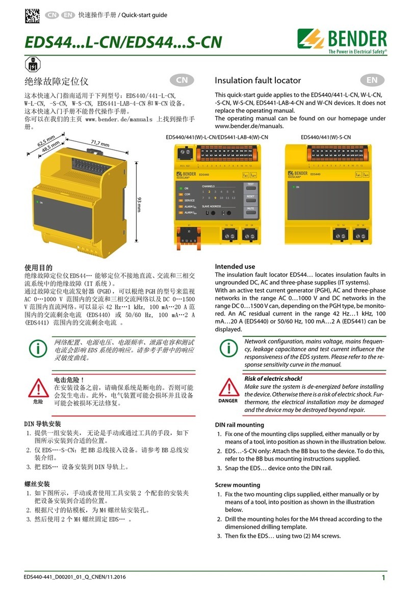
Bender EDS44 L-CN Series User manual
Bender
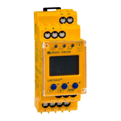
Bender cme420 User manual

Bender
Bender IOM441-S User manual
