Beninca DA.C15 User manual

DA.C15
®
CENTRALINA A MICROPROCESSORE
CONTROL UNITWITH MICROCONTROLLER
MIKROCONTROLLER-STEUERUNG
CENTRALE A MICROCONTRÔLEUR
CENTRALITA A MICROPROCESADOR
AUTOMATISMI PER CANCELLI
®
L8542603
Rev. 04/00/01
Libro istruzioni
Operating instructions
Betriebsanleitung
Livret d’instructions
Libro de instrucciones
UNIONE NAZIONALE COSTRUTTORI
AUTOMATISMI PER CANCELLI, PORTE,
SERRANDE ED AFFINI
A
Z
I
E
N
D
A
C
E
R
T
I
F
I
C
A
T
A
UNI
EN ISO
9001

2
Dichiarazione CE di conformità Déclaration CE de conformité
EC declaration of confirmity Declaracion CE de conformidad
EG-Konformitatserklarung
Con la presente dichiariamo che il nostro prodotto
We hereby declare that our product
Hiermit erklaren wir, dass unser Produkt
Nous déclarons par la présente que notre produit
Por la presente declaramos que nuestro producto
DA.C15
è conforme alle seguenti disposizioni pertinenti:
complies with the following relevant provisions:
folgenden einschlagigen Bestimmungen entspricht:
correspond aux dispositions pertinentes suivantes:
satisface las disposiciones pertinentes siguientes:
Direttiva sulla compatibilità elettromagnetica (89/336/
CCE, 93/68/CEE)
EMC guidelines (89/336/EEC, 93/68/EEC)
EMV-Richtlinie (89/336/EWG, 93/68/EWG)
Directive EMV (89/336/CCE, 93/68/CEE) (Compatibilité
électromagnétique)
Reglamento de compatibilidad electromagnética (89/336/
MCE, 93/68/MCE)
Norme armonizzate applicate in particolare:
Applied harmonized standards, in particular:
Angewendete harmonisierte Normen, insbesondere:
Normes harmonisée utilisées, notamment:
Normas armonizadas utilzadas particularmente:
EN 55022, EN 61000-3-2, EN 61000-3-3, EN 50082-1
Norme e specifiche tecniche nazionali applicate in
particolare:
Applied national technical standards and specifications, in
particular:
Angewendete nationale Normen und technische
Spezifikationen, insbesondere:
Normes et specifications techniques nationales qui ont été
utilisées, notamment:
Normas y especificaciones técnicas nacionales que se
utilizaron particularmente:
UNI 8612
Data/Firma
Direttiva sulla bassa tensione (73/23/CEE, 93/68/CEE)
Low voltage guidelines (73/23/EEC, 93/68/EEC)
Tiefe Spannung Richtlinie (73/23/EWG, 93/68/EWG)
Directive bas voltage (73/23/CEE, 93/68/CEE)
Reglamento de bajo Voltaje (73/23/MCE, 93/68/MCE)
Norme armonizzate applicate in particolare:
Applied harmonized standards, in particular:
Angewendete harmonisierte Normen, insbesondere:
Normes harmonisée utilisées, notamment:
Normas armonizadas utilzadas particularmente:
EN 60204-1, EN 60335-1
Data/Firma
AUTOMATISMI PER CANCELLI
®
Automatismi Benincà Srl
Via Scamozzi, 3
36030 MONTECCHIO P. VI
ITALIA

3
1
28 29 30 31
ANT.
23
L3
F4
F1
F2
SENS_H
2A
2d Ch.
F3
D5
F1-2
F1-3
D6
D7
RL1
RL3
M3 M4
M
SELEZIONE TENSIONE
DI ALIMENTAZIONE
M5
LAMP. 230V SCA
24VAC
Z9
Z10
Z11
Z12
Z13
Z14
R52
R15
R28 R33
R3
R2
R1
R32
R31
R36
R37
R38
R39
R30
R4
Z8
R11
R9
R16
R40
C25 ASA
ASC
FTC
FCA
FCC
STOP
PED
SW1
P.P.
AP.
CH.
D27 D20 D19 D22
D18
D17
D16
D15
D14
D13
D12
D11
D10
D9
Z1
Z18
Z17
Z16
Z15
C10
Q2
Q3
Q4
Q6
D1 D3
D4
D21 D24 D23 D26 D25 D28
R44
R45
R46
R17
R51
R50
R49
R48
R47
C20
C21
C22
C25
1
C2 D2
D29
D2
P1
C17
C1
VDR2
D5
C5 U4
U3 C18
J1
J3
C5
C7
J2
C19C8
Q1
U1 +
+
D6
+C3
PGM
POWER
RTX
TCATL
C4
2345678910
C24
C26
C27
C28
C9
R61
R60
R59
R58
R57
R56
R55
R54
R53
R11
R43
R35
R42
R39
R41
R13
R6
R5
R12
R62
+V
ASA
ASC
FTC
FCA
FCC
STOP
PED
P.P.
APRE
CHIUDE
M8 M7 M1
4
230V 380V
5 6 7 8 9 10 11 12 13 14 15 16 17 18 19 20 21 22 23 24 25 26 27
RL5
D8R34 R7
F5 0,5A
FF2FF1
FF3
FF4
6.3A
6.3A
6.3A
30
FUSE
FUSE
FUSE
FUSE
FUSE
24
0 230 380
30
L2/F
L1/N
®
Divisione Elettronica
DA.C15/DA.C15P/DA.C15I v.1.0

4
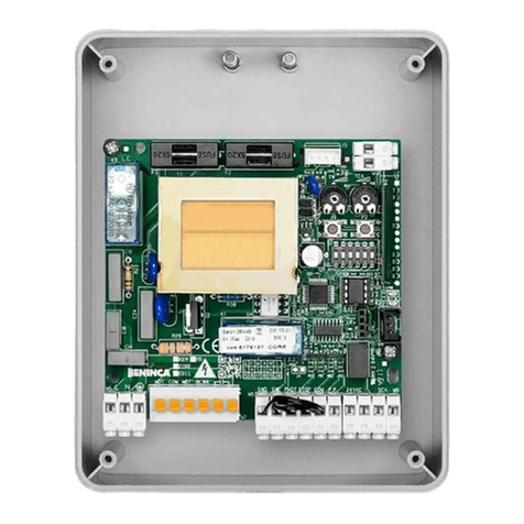
Centralina DA.C15
La centralina a microprocessore DA.C15 può essere usata con motori di potenza non superiore a 1500W.
Se la centrale è alimentata a 380V, si consiglia di sostituire i 3 fusibili da 6.3A, situati vicino alla morsettiera di
alimentazione, con i 3 fusibili da 4A contenuti nella busta fissata al contenitore della centrale.
Consigli per l’installazione.
a) L’installazione elettrica e la logica di funzionamento devono essere in accordo con le normative vigenti.
b) È consigliabile tenere i cavi di potenza (motore, alimentazione) distinti da quelli di comando (pulsanti,
fotocellule, radio); per evitare interferenze è preferibile prevedere ed utilizzare due guaine separate (vedi
EN 60204-1 15.1.3).
c) Ricontrollare tutti i collegamenti fatti prima di dare tensione.
d) Controllare che le impostazioni dei Dip-Switch siano quelle volute.
e) Dando tensione il led ”POWER” si deve illuminare, in caso contrario controllare l’integrità dei fusibili e la
presenza di 230Vac 50Hz tra i morsetti 1 e 2 (INPUT 230VAC - rispettare fase/neutro).
f) Tutti gli ingressi N.C.non utilizzati devono essere ponticellati con il comune ”+V”.
g) Nel caso in cui il senso di rotazione del motore sia invertito basta invertire i fili ”APRE” - ”CHIUDE” del
motore stesso e i fili dei finecorsa ”FCA” - ”FCC”.
Funzione Ingressi/Uscite
(1,2,3) INPUT 230/380VAC= Alimentazione centralina 230/380Vac 50Hz
(rispettare fase/neutro:1= Neutro o L1,2= Fase o L2,3= L3).
(4,5,6) SELEZIONE TENSIONE DI ALIMENTAZIONE
Collegare i morsetti 4 e 5 se la centrale è alimentata a 230Vac
Collegare i morsetti 6 e 5 se la centrale è alimentata a 380Vac
(7,8,9) APRE/CHIUDE/COM= Ai rispettivi morsetti del motore a 230/380VAC 50Hz.
(è obbligatorio collegare il filo di Terra - giallo/verde sulla carcassa del motore)
(10,11) LAMP230= Al lampeggiante a 230Vac.
(12,13) OUT 24VAC= Uscita alimentazione ausiliaria 24Vac (1A max.).
(14,15) SCA= Uscita ”Spia cancello aperto” 24Vac.
L’uscita della spia cambia in funzione dello stato della centrale:
• Spenta a cancello chiuso.
• Lampeggiante lentamente durante la fase di apertura.
• Lampeggiante velocemente durante la fase di chiusura.
• Accesa a cancello fermo in apertura
(16,17) +V= Comune a tutti gli ingressi di comando
(18) ASA= Ingresso dispositivo antischiacciamento in apertura (contatto n.c.): l’apertura del contatto duran-
te la fase di apertura provoca l’inversione della marcia per pochi centimetri e quindi l’arresto.
(19) ASC= Ingresso dispositivo antischiacciamento in chiusura (contatto n.c.):l’apertura del contatto duran-
te la fase di chiusura provoca l’inversione della marcia per pochi centimetri e quindi l’arresto.
(20) FTC= Ingresso ricevitore fotocellula (contatto n.c.).
(21) FCA= Ingresso finecorsa Apre (contatto n.c.).
(22) FCC= Ingresso finecorsa Chiude (contatto n.c.)
(23) STOP= Ingresso pulsante di STOP (contatto n.c.)
(24) PED= Ingresso pulsante PEDONALE (contatto n.o.)
(25) P.P.= Ingresso pulsante PASSO/PASSO (contatto n.o.)
(26) APRE= Ingresso pulsante APRE (contatto n.o.)

5
(27) CHIUDE= Ingresso pulsante CHIUDE (contatto n.o.)
(28,29) ANT.= Ingresso antenna scheda radio
(30,31) RX 2CH.= Contatto 2°canale scheda radio (contatto n.o.)
J2 SENS_H= Ingresso per scheda dispositivo antischiacciamento (opzionale) ”DA.AS”.
N.B.: In assenza di tale centralina ponticellare i pin centrali 2,3.
Funzione Dip-Switch
N.B.: Ogni cambio di funzione deve essere eseguito in assenza di tensione.
DSW1 Sceglie il tipo di funzionamento del ”Pulsante P.P.” e del telecomando.
Off: Funzionamento:”APRE” - ”STOP” - ”CHIUDE”
On: Funzionamento: ”APRE” - ”CHIUDE” - ”APRE”
DSW2 Abilita o disabilita la richiusura automatica.
Off: Richiusura automatica abilitata
On: Richiusura automatica disabilitata
DSW3 Abilita o disabilita la funzione condominiale (dopo il primo comando di apertura il ”Pulsante P.P.”, e il
telecomando vengono resi inattivi).
Off: Funzione condominiale disabilitata
On: Funzione condominiale abilitata
DSW4 Abilita o disabilita il prelampeggio
Off: Prelampeggio disabilitato
On: Prelampeggio abilitato
DSW5 Sceglie il tipo di intervento dell’ingresso ”FTC” in apertura.
Off: Nessun intervento
On: Stop temporaneo
DSW6 Sceglie il tipo di funzionamento arresto comandato dal pulsante ”P.P.”.
Off: L’arresto in fase di apertura consente la chiusura automatica (se abilitata)
On: L’arresto in fase di apertura esclude la chiusura automatica.
DSW7 Abilita o disabilita l’intervento del sensore di giri durante la fase di apertura.
Off: Intervento sensore di giri abilitato.
On: Intervento sensore di giri disabilitato.
DSW8 Abilita / disabilita l’inversione comandata dall’ingresso ”ASC” dopo l’attivazione del fine corsa di chiusura.
La funzione permette di collegare una costa sensibile sul bordo di chiusura, senza che questa provochi
l’inversione di marcia quando la porta si deve chiudere completamente.Il fine corsa di chiusura deve
essere posizionato in modo da intervenire quando mancano alcuni centimetri alla chiusura della porta.
Off: Abilitata:l’ingresso ”ASC” comanda sempre l’inversione di marcia per alcuni centimetri.
On: Disabilitata: dopo l’attivazione del fine corsa di chiusura, l’ingresso ”ASC” arresta il motore.
DSW9 Non utilizzato.
DSW10 Non utilizzato.
Funzione deiTrimmer
TCA Permette di regolare il tempo di richiusura automatica quando è abilitata posizionando il Dip-Switch
”DSW2”= Off.
La regolazione varia da un minimo di 10 sec. ad un massimo di 200 sec.
Il tempo minimo si ottiene ruotando il trimmer tutto in senso antiorario.
TL Permette di regolare il tempo di lavoro dell’automatismo oltre il quale interverrà la protezione software
nel caso in cui i finecorsa si guastassero (posizionarlo circa 4 sec. in più del tempo di corsa effettiva
dell’automatismo).
La regolazione varia da un minimo di 10 sec. ad un massimo di 200 sec.
Il tempo minimo si ottiene ruotando il trimmer tutto in senso antiorario.

6
DA.C15 Control unit with microcontroller
The ”DA.C15” control unit with microcontroller is suitable for motors with up to 1500W power.
If the control unit is powered at 380V, it is advisable to replace the three 6.3A fuses located near the
power supply terminal board with the three 4A fuses in the envelope stuck to the central box.
Installation instructions.
a) The electrical installation and functioning logic must comply with current standards.
b) Keep the power cables (for the motor and power supply) away from the control cables (buttons,
photocells, radio).To avoid interference use two separate sheaths (see EN 60204-1 15.1.3).
c) Check all the connections again before supplying voltage.
d) Check that the Dip-Switch settings are as required.
e) When voltage is supplied, the ”POWER” led should light up. If this is not the case, check the state
of the fuses and whether 230VAC 50Hz power is present between terminals 1 and 2 (INPUT 230VAC
- respect phase/neutral wire position).
f) The N.C. inputs not used must be connected to the common ”+V”.
g) If the direction of the motor rotation is not correct,invert the ”OPEN”- ”CLOSE” wires of the motor
as well as the wires of the ”FCA” - ”FCC”limit switches.
Input/Output functions
(1,2,3) INPUT 230/380VAC= Control unit 230/380VAC 50Hz power supply
(respect phase/neutral wire position: 1= Neutral or L1,2= Phase or L2,3= L3)
(4,5,6) SELEZIONETENSIONE DI ALIMENTAZIONE
Connect terminals 4 and 5 if the control unit is powered at 230VAC
Connect terminals 6 and 5 if the control unit is powered at 380VAC
(7,8,9) APRE/CHIUDE/COM= Connection to the corresponding 230/380VAC 50Hz motor terminals
(the earth wire (green/yellow) must be connected to the motor housing).
(10,11) LAMP230= Connection to the 230VAC blinker.
(12,13) OUT 24VAC= 24VAC auxiliary power supply output (1A max.).
(14,15) SCA= Output “Open gate indicator”, 24VAC.
The output of the LED changes according to the status of the control unit:
• Off with gate in the closed position
• Slowly flashing during the opening phase
• Rapidly flashing during the closing phase
• On with gate stopped in the open position
(16,17) +V= Common connection to all the control inputs.
(18) ASA= Input of anti-crash device in the opening phase (normally closed contact): the opening of
the contact in the opening phase causes the movement reversion for a few centimetres and
then the stopping of the movement.
(19) ASC= Input of anti-crash device in the closing phase (normally closed contact): the opening of
the contact in the closing phase causes the movement reversion for a few centimetres and
then the stopping of the movement.
(20) FTC= Photocell receiver input (n.c. contact).
(21) FCA= Limit switch input - Opening (n.c. contact).
(22) FCC= Limit switch input - Closing (n.c. contact).
(23) STOP= STOP button input (n.c. contact).
(24) PED= PEDESTRIAN button input (n.o. contact)
(25) P.P.= STEP-by-STEP button input (n.o. contact).
(26) APRE= OPEN button input (n.o. contact).

7
(27) CHIUDE= CLOSE button input (n.o. contact).
(28,29) ANT.= Input of radio board antenna
(30,31) RX 2CH.= Radio board 2nd channel contact (n.o. contact).
J2 SENS_H= Input for optional anti-crash card ”DA.AS”
If this control unit is not used, the central pins 2, 3 should be short-circuited.
Dip-switch functions
N.B.: Every change of functions have to be done without electricity.
DSW1= This selects the type of functioning of the P.P. button and Remote control.
Off= ”OPEN”- ”STOP” - ”CLOSE”functioning
On= ”OPEN” - ”CLOSE” - ”OPEN” functioning.
DSW2= This enables or disables the automatic re-closing.
Off= Automatic re-closing enabled
On= Automatic re-closing disabled
DSW3= This enables or disables the apartment building function (after the first opening command,the
P.P. button and the Remote control are deactivated).
Off= Apartment building function disabled.
On= Apartment building function enabled.
DSW4= This enables or disables the pre-blinking function
Off= Pre-blinking disabled.
On= Pre-blinking enabled.
DSW5= This selects the type of intervention of the ”FTC” input on opening
Off= No intervention
On=Temporary stop
DSW6= Select the type of stop controlled by the ”P.P.” push-button.
Off=The stopping in the opening phase allows the automatic closure (if enabled).
On=The stopping in the opening phase inhibits the automatic closure.
DSW7= It enables or disables the rounds sensor triggering in the opening phase.
Off= Round sensor triggering enabled.
On= Rounds sensor triggering disabled.
DSW8= Enables/Disables the reversion of movement controlled by the“ASC”input,after the activation
of the closing limit switch. This function permits to connect a sensitive rubber edge on the
edge of the gate closing leaf avoiding that the sensitive device causes the movement reversion
when the door must be completely closed. The closing limit switch should be positioned so
that it is triggered when a few centimetres are missing to the complete closure of the gate.
Off= Enabled: the “ASC” input always controls the movement reversion for some centimetres.
On = Disabled:After the activation of the closure limit switch,the“ASC”input stops the motor.
DSW9= Spare.
DSW10= Spare.
Trimmer functions
TCA= This allows the automatic re-closing time to be adjusted when this is enabled by positioning the
DSW2 Dip-switch on OFF.
Adjustment can be from a minimum of 10 to a maximum of 200 seconds.
The minimum time is obtained by rotating the trimmer completely anticlockwise.
TL= This allows the working time of the automation to be adjusted.If the limit switches fail, the soft-
ware protection will intervene after this time has elapsed.
(Add about 4 sec. to the actual stroke time of the automation).
Adjustment can be from a minimum of 10 to a maximum of 200 seconds.
The minimum time is obtained by rotating the trimmer completely anticlockwise.

8
STEUERUNG ”DA.C15”
Die Mikrocontroller-Steuerung “DA.C15” kann mit Motoren mit einer Leistung nicht über 1500W verwendet werden.
Falls die Zentrale zu 380V gespeist wird, empfehlen wir die 3 Sicherungen zu 6.3A in der Nähe der Klemmleiste
mit den 3 Sicherungen zu 4A auszuwechseln, die sich in der Tüte befinden, die am Behälter der Zentrale
befestigt ist.
Empfehlungen für den Einbau
a) Der elektrische Einbau sowie die Funktionslogistik müssen mit den geltenden Richtlinien im Einklang sein.
b) Wir empfehlen, die Stromkabel (Motor, Zufuhr) von den Steuerkabeln (Drucktasten, Lichtschranken, Emp-
fänger) unterscheidbar zu halten; um Störungen zu vermeiden ist es ratsam, zwei getrennte Kabelmäntel
vorzusehen und anzuwenden (siehe EN 60204-1 15.1.3).
c) Sämtliche gemachten Anschlüsse vor der Stromzugabe erneut überprüfen.
d) Überprüfen, ob die Einstellungen der DIP-Drucktasten den gewünschten entsprechen.
e) Bei Stromzugabe muß die LED-Diode “POWER” leuchten.Falls nicht der Fall, überprüfen, ob die Siche-
rungen ganz sind und ob zwischen den Klemmen 1 und 2 (INPUT 230VAC - Phase/Neutral beachten)
230VAC 50Hz gegeben ist.
f) Die N.C.Eingaben, die nicht verwendet werden, mit dem Mittelleiter ”+V” überbrücken.
g) Falls die Drehrichtung des Motors vertauscht ist, genügt es, die Drähte “ÖFFNET” - “SCHLIESST” des
Motors selbst und die Drähte des Endschalters “FCA” - “FCC” zu vertauschen.
Funktion Eingaben/Ausgaben
(1,2,3) INPUT 230/380VAC= Zufuhr Steuerung 230/380VAC 50Hz.
(Phase/Neutral beachten: 1= Neutral oder L1,2= Phase oder L2,3= L3)
(4,5,6) SELEZIONE TENSIONE DI ALIMENTAZIONE
Die Klemmen 4 und 5 verbinden, wenn die Zentrale mit 230VAC gespeist wird.
Die Klemmen 6 und 5 verbinden, wenn die Zentrale mit 380VAC gespeist wird.
(7,8,9) APRE/CHIUDE/COM= An die entsprechenden Motorklemmen 230/380VAC 50Hz.
(Es istVorschrift, den Erdleiter (gelb/grün) mit dem Motorgehäuse zu verbinden)
(10,11) LAMP230= An 230VAC Blinkleuchte.
(12,13) OUT 24VAC= Ausgabe Hilfszufuhr 24VAC (max. 1A).
(14,15) SCA= Ausgang “Meldelleucht für offenesTor” 24Vac.
Der Ausgang der Meldeleuchte wird je nach Zustand der Zentrale geändert:
• Ausgeschaltet, wenn das Tor geschlossen ist.
• Langsam blinkend, beim Öffnen.
• Schnell blinkend, beim Schließen.
• Eingeschaltet, wenn das Tor beim Öffnen anhält.
(16,17) +V= Gemeinsam bei allen Steuereingaben.
(18) ASA= Eingang Schutzvorrichtung gegen Quetschung beim Öffnen (Arbeitskontakt): wird der Kontakt
beim Öffnen geöffnet, schaltet die Gangrichtung wenige Zentimeter lang um und hält dann an.
(19) ASC= Eingang Schutzvorrichtung gegen Quetschung beim Schließen (Arbeitskontakt): wird der Kon-
takt beim Schließen geöffnet, schaltet die Gangrichtung wenige Zentimeter lang um und hält dann an.
(20) FTC= Eingabe Lichtschrankenempfänger (Ruhekontakt)
(21) FCA= Eingabe Endschalter Öffnet (Ruhekontakt)
(22) FCC= Eingabe Endschalter Schließt (Ruhekontakt)
(23) STOP= Eingabe STOP-Drucktaste (Ruhekontakt)
(24) PED= Eingabe Drucktaste Flügel FUSSGÄNGER (Arbeitskontakt)
(25) P.P.= Eingabe SCHRITT/SCHRITT-Drucktaste (Arbeitskontakt)
(26) APRE= Eingabe ÖFFNET-Drucktaste (Arbeitskontakt)

9
(27) CHIUDE= Eingabe SCHLIESST-Drucktaste (Arbeitskontakt)
(28,29) ANT.= Eingabe Antenne Empfängersteckkarte
(30,31) RX 2CH.= Kontakt 2. Kanal Empfängersteckkarte (Arbeitskontakt)
(J2) SENS_H= Eingang für quetschbeständige Karte (Option) ”DA.AS”.
N.B.: wenn keine Zentrale vorgesehen ist, Pin 2 und 3 überbrücken.
Funktion der Dip-Drucktasten
Anmerkung: Alle Funktionsänderung muß in Mangel von Spannung verricht werden.
DSW1= Wählt die Funktionsart der “P.P.-Drucktaste” und der Fernsteuerung
Off= Funktion “ÖFFNET” - ”STOP” - ”SCHLIESST”
On= Funktion “ÖFFNET” - ”SCHLIESST” - ”ÖFFNET”
DSW2= Aktiviert oder deaktiviert die automatische Wiederschließung
Off= Automatische Wiederschließung aktiviert
On= Automatische Wiederschließung deaktiviert
DSW3= Aktiviert oder deaktiviert die Mehrfamilienhaus-Funktion (nach dem ersten Öffnungsbefehl werden
die “P.P.-Drucktaste” und die Fernsteuerung deaktiviert)
Off= Mehrfamilienhaus-Funktion deaktiviert
On= Mehrfamilienhaus-Funktion aktiviert
DSW4= Aktiviert oder deaktiviert die Vorblinkleuchte.
Off= Vorblinkleuchte deaktiviert
On= Vorblinkleuchte aktiviert
DSW5= Wählt die Eingriffsart der Eingabe “FTC” bei Öffnung
Off= Kein Eingriff
On= Vorübergehend Stop
DSW6= Wahl des Haltesystems, gesteuert durch die Taste ”P.P.”
Off= Das Anhalten beim Öffnen, ermöglicht das automatische Schließen (wenn freigegeben)
On= Das Anhalten beim Öffnen, schließt den automatischen Schließvorgang aus.
DSW7= Der Umdrehungsgeber wird hiermit beim Öffnen freigegeben oder ausgeschaltet.
Off= Umdrehungsgeber freigegeben
On= Umdrehungsgeber ausgeschlossen.
DSW8= Umschaltung am ASC Eingang nach der Aktivierung des Endschalters des Schließvorganges freige-
ben/nicht freigeben.Die Funktion ermöglicht es das empfindliche Verschlussprofil anzuschließen, ohne
dadurch die Umschaltung zu bewirken, wenn dieTür geschlossen werden muss.Der Endschalter des
Schließvorganges muss so positioniert sein, dass er einige Zentimeter vorTürverschluss einschaltet.
Off= freigegeben: der ASC Eingang steuert immer die Umschaltung einige Zentimeter lang
On= nicht freigegeben: nach dem Einschalten des Endschalters des Schließvorgangs, hält der ASC
Eingang den Motor an.
DSW9= nicht benutzt.
DSW10= nicht benutzt.
Funktion derTrimmer
TCA= Wenn aktiviert, erlaubt er die Einstellung der automatischenWiederschließzeit durch Stellen der DIP-
Drucktaste auf “DSW2” = Off.
Die Einstellung variiert von mindestens 10 bis max. 200 Sek.
Die Minimalzeit erhält man durch Drehen des Trimmers gegen den Uhrzeigersinn.
TL= Erlaubt die Einstellung der Antriebbetriebszeit, über die der Software-Sicherung eingreift, falls die
Endschalter beschädigt sein sollten (auf ca. 4 Sek. länger als die effektive Laufzeit des Antriebs
stellen).
Die Einstellung variiert von mindestens 10 bis max. 200 Sek.
Die Minimalzeit erhält man durch Drehen des Trimmers gegen den Uhrzeigersinn.

10
Centrale ”DA.C15”
La centrale à microcontrôleur “DA.C15” peut être utilisée avec des moteurs ayant une puissance non
supérieure à 1500W.
Si la centrale est alimentée à 380V, il est conseillé de remplacer les fusibles de 6.3A, situés à proximité de la
boîte à bornes d’alimentation,par 3 fusibles de 4A contenus dans la poche fixée au conteneur de la centrale.
Conseils pour l’installation
a) L’installation électrique et la logique de fonctionnement doivent être conformes aux normes en
vigueur.
b) Il est conseillé de maintenir les câbles de puissance (moteur, alimentation) séparés de ceux de
commande (touches,cellules photoélectriques,radio); afin d’éviter des interférences,il est préféra-
ble de prévoir et d’utiliser deux gaines séparées (voir EN 60204-1 15.1.3).
c) Recontrôler toutes les connexions effectuées avant d’appliquer la tension.
d) S’assurer que les réglages des interrupteurs DIP soient corrects.
e) En appliquant la tension, la DEL “POWER”doit s’allumer; si cela n’était pas le cas, contrôler le bon
fonctionnement des fusibles et la présence des 230Vc.a.50Hz entre les bornes 1 et 2 (INPUT 230Vc.a.
- respecter phase/neutre).
f) Réaliser un pontet entre les entrées N.C. pas utilisées et le commun“+V”.
g) Si le sens de rotation du moteur est inversé, il suffit d’inverser les fils “OUVRE” - “FERME” du
moteur et les fils des fin de course“FCA”- “FCC”.
Fonction Entrées/Sorties
(1,2,3) INPUT 230/380VAC= Alimentation centrale 230/380Vc.a. 50Hz
(respecter phase/neutre: 1= Neutre ou L1,2= Phase ou L2,3= L3)
(4,5,6) SELEZIONE TENSIONE DI ALIMENTAZIONE
Brancher les bornes 4 et 5 si la centrale est alimentée à 230VCA.
Brancher les bornes 6 et 5 si la centrale est alimentée à 380VCA.
(7,8,9) APRE/CHIUDE/COM= Aux bornes correspondantes du moteur 230/380Vc.a. 50Hz
(il est obligatoire de connecter le fil de terre (jaune/vert) à la carcasse du
moteur)
(10,11) LAMP230= Au feu clignotant à 230Vc.a.
(12,13) OUT 24VAC= Sortie alimentation auxiliaire 24Vc.a. (1A maxi)
(14,15) SCA= Sortie ”Voyant portail ouvert” 24Vc.a.
La sortie du voyant change en fonction de l’état de la centrale:
• Eteint avec portail fermé.
• Clignote lentement durant l’ouverture.
• Clignote rapidement durant la fermeture.
• Allumé avec portail arrêté en ouverture.
(16,17) +V= Commun à toutes les entrées de commande
(18) ASA= Entrée dispositif anti-écrasement en ouverture (contact n.f.): l’ouverture du contact du-
rant l’ouverture provoque l’inversion de marche pendant quelques centimètres, puis l’arrêt.
(19) ASC= Entrée dispositif anti-écrasement en fermeture (contact n.f.): l’ouverture du contact du-
rant la fermeture provoque l’inversion de marche pendant quelques centimètres, puis l’arrêt.
(20) FTC= Entrée récepteur cellule photoélectrique (contact n.f.)
(21) FCA= Entrée fin de course Ouvre(contact n.f.)
(22) FCC= Entrée fin de course Ferme (contact n.f.)
(23) STOP= Entrée touche STOP (contact n.f.)
(24) PED= Entrée touche PASSAGE PIETON (contact n.o.)
(25) P.P.= Entrée touche PAS ò PAS (contact n.o.)

11
(26) APRE= Entrée touche OUVRE (contact n.o.)
(27) CHIUDE= Entrée touche FERME (contact n.o.)
(28,29) ANT.= Entrée antenne carte radio
(30,31) RX 2CH.= Contact 2e canal carte radio (contact n.o.)
(J2) SENS_H= Entrée pour carte anti-écrasement (en option) ”DA.AS”
N.B.: En l’absence de cette centrale, relier par un pontet les pins centraux 2, 3.
Fonction interrupteurs DIP
N.B.: Tous les échanges de fonction doivent être effectués dans l’absence de tension.
DSW1= Choisit le type de fonctionnement de la “Touche P.P.” et de la télécommande
Off= Fonctionnement “OUVRE” - ”STOP” - ”FERME”
On= Fonctionnement “OUVRE” - ”FERME” - ”OUVRE”
DSW2= Active ou désactive la refermeture automatique
Off= Refermeture automatique activée
On= Refermeture automatique désactivée
DSW3= Active ou désactive la fonction pour ensembles collectifs d’habitation (après la première com-
mande d’ouverture, la “Touche P.P.” et la télécommande sont rendues inactives)
Off= Fonction pour ensembles collectifs d’habitation désactivée
On= Fonction pour ensembles collectifs d’habitation activée
DSW4= Active ou désactive le préclignotement
Off= Préclignotement désactivé
On= Préclignotement activé
DSW5= Choisit le type d’intervention de l’entrée “FTC” en ouverture
Off= Aucune intervention
On= Stop provisoire
DSW6= Sélectionne le type d’arrêt commandé par la touche ”P.P.”.
Off= L’arrêt durant l’ouverture consent la fermeture automatique (si validée).
On= L’arrêt durant l’ouverture coupe la fermeture automatique.
DSW7= Valide ou invalide l’intervention du capteur de tours durant l’ouverture.
Off= Intervention du capteur de tours validée.
On= Intervention du capteur de tours invalidée.
DSW8= Valide / invalide l’inversion commandée par l’entrée ”ASC”après l’activation du fin de course
de fermeture. Cette fonction permet de relier un bourrelet sensible sur le bord de fermeture
sans que cela provoque l’inversion de marche lorsque la porte doit se fermer complètement.
Le fin de course de fermeture doit être mis en place de manière à intervenir quelques centimè-
tres avant la fermeture de la porte.
Off=Valide: l’entrée ”ASC”commande toujours l’inversion de marche sur quelques centimètres.
On= Invalide: après l’activation du fin de course de fermeture, l’entrée ”ASC”arrête le moteur.
DSW9= Non utilisé.
DSW10= Non utilisé.
Fonction des potentiomètre
TCA= Permet de régler le temps de refermeture automatique, si elle est activée, en positionnant l’in-
terrupteur DIP “DSW2” sur Off.
Le réglage varie d’un minimum de 10 s. jusqu’à un maximum de 200 s.
Le temps minimum s’obtient en tournant le condensateur d’équilibrage complètement dans le
sens inverse des aiguilles d’une montre.
TL= Permet de régler le temps de travail de l’automatisme après lequel la protection du logiciel
interviendra si les fin de course présentent une défaillance. (Le placer à 4 s.en plus du temps
de course effectif de l’automatisme).
Le réglage varie d’un minimum de 10 s. jusqu’à un maximum de 200 s.
Le temps minimum s’obtient en tournant le condensateur d’équilibrage complètement dans le
sens inverse des aiguilles d’une montre.

12
Centralita a microprocesador DA.C15
La centralita a microprocesador “DA.C15” puede ser usada con motores de pontencia no superior a 1500W.
Si la central está alimentada con 380V se aconseja reemplazar los 3 fusibles de 6.3A situados cerca de la
regleta de alimentación con los 3 fusibles de 4A contenidos en el sobre asegurado al contenedor de la central.
Consejos para la instalacion
a) La instalación eléctrica y la lógica de funcionamiento deben estar de acuerdo con la normativa vigente.
b) Es aconsejable tener los cables de potencia (motor, alimentación) separados de los de mando (pulsado-
res, fotocélulas, radio) para evitar interferencias es preferible preveer de utilizar dos tubos separados
(véase EN 60204-1 15.1.3).
c) Repasar todas las conexiones hechas antes de dar tensión.
d) Controlar que el posicionamiento de los Dip-Switch sean los deseados.
e) Dando tensión el led ”Power”se debe iluminar, en caso contrario comprobar la integridad de los fusibles y
la presencia de 230VAC 50 Hz entre los bornes 1 y 2 (INPUT 230VAC - respetar fase/neutro).
f) Las entradas N.C. no utilizadas deben ser puenteadas con el común ”+V”.
g) En caso de que el sentido de rotación del motor esté invertido, basta con invertir los cables ”APRE” -
”CHIUDE” del propio motor y los finales de carrera ”FCA” - ”FCC”.
Funcion Entradas / Salidas
(1,2,3) INPUT 230/380VAC= Alimentación centralita 230/380VAC 50Hz
(respetar fase/neutro:1= Neutro o L1,2= Fase o L2,3= L3)
(4,5,6) SELEZIONE TENSIONE DI ALIMENTAZIONE
Conectar los bornes 4 y 5 si la central está alimentada con 230VCA
Conectar los bornes 6 y 5 si la central está alimentada con 380VCA
(7,8,9) APRE/CHIUDE/COM= A los respectivos bornes motor 230/380VAC 50Hz
Es obligatorio conectar el cable de tierra - amarillo/verde) a la carcasa del motor
(10,11) LAMP 230= Al relampagueador a 230VAC
(12,13) OUT 24VAC= Salida alimentación auxiliar 24VDC (1A máximo )
(14,15) SCA= Salida ”Piloto verja abierta” 24Vca.
La salida del piloto cambia según el estado de la central:
• Apagado con la verja cerrada.
• Intermitente lento durante la fase de apertura.
• Intermitente rápido durante la fase de cierre.
• Encendido fijo con verja parada en apertura
(16,17) +V= Comùn para todas las entradas de mando
(18) ASA= Entrada dispositivo antiaplastamiento en apertura (contacto n.c.): la apertura del contacto du-
rante la fase de apertura provoca la inversión de la marcha por pocos centímetros y seguidamente la
parada.
(19) ASC= Entrada dispositivo antiaplastamiento en cierre (contacto n.c.):la apertura del contacto durante
la fase de cierre provoca la inversión de la marcha por pocos centímetros y seguidamente la parada.
(20) FTC= Entrada receptor fotocélula apertura (contacto n.c.)
(21) FCA= Entrada final de carrera Abre (contacto n.c.)
(22) FCC= Entrada final de carrera Cierra (contacto n.c.)
(23) STOP= Entrada pulsador STOP ( contacto n.c.)
(24) PED= Entrada pulsador PEATONAL (contacto n.o.)
(25) P.P.= Entrada pulsador PASO A PASO (contacto n.o.)
(26) APRE= Entrada pulsador ABRIR (contacto n.o.)

13
(27) CHIUDE= Entrada pulsador CERRAR ( contacto n.o.)
(28,29) ANT.= Entrada antena tarjeta radio
(30,31) RX 2CH. = Contacto 2°canal tarjeta radio (contacto n.o.)
(J2) SENS_H= Entrada para tarjeta antiaplastamiento (opción) ”DA.AS”.
N.B.: Faltando esta centralita es preciso puentear los pin centrales 2, 3.
Funcion Dip-Switch
Nota: Para cambio de función debe ser realizado en ausencia de tensión.
DSW1= Elige el tipo de funcionamento del “Pulsador P. P.“ y del Radiomando
OFF: Funcionamento “APRE “ - ”STOP” - “CHIUDE”
ON: Funcionamento “APRE “ - “CHIUDE” - “APRE “
DSW2= Habilita o deshabilita el cierre automático
OFF: Cierre automático habilitado
ON: Cierre automático deshabilitado
DSW3= Habilita o deshabilita la función comunitaria (después del primer mandato de apertura el “Pulsador
P.P.“ y el Radiomando quedan inactivos)
OFF: Función comunitaria deshabilitada
ON: Función comunitaria habilitada
DSW4= Habilita o deshabilita el prerrelampagueo
OFF: Prerrelampagueo deshabilitado
ON: Prerrelampagueo habilitado
DSW5= Elige el tipo de intervención de la entrada ”FTC” en apertura
OFF: Ninguna intervención
ON: Stop temporal
DSW6= Elegir el tipo de parada controlada por el botón ”P.P.”.
OFF: La parada en fase de apertura permite el cierre automático (si habilitado).
ON: La parada en fase de apertura excluye el cierre automático.
DSW7= Habilita o inhabilita la intervención del sensor de vueltas durante la fase de apertura.
OFF: Intervención habilitada del sensor de vueltas
ON: Intervención inhabilitada del sensor de vueltas.
DSW8= Habilita / inhabilita la inversión mandada por la entrada ”ASC” tras la activación del final de carrera de
cierre.La función permite conectar un borde sensible sobre el borde de cierre, sin que cause la inversión
de la dirección de marcha cuando la puerta debe cerrarse completamente. El final de carrera de cierre
debeestarcolocadodemaneraqueintervengacuandofaltan unos centímetros para el cierre de la puerta.
OFF:Habilitada:la entrada ”ASC”manda siempre la inversión de la dirección de marcha en unos centímetros.
ON: Inhabilitada: tras la activación del final de carrera de cierre, la entrada ”ASC” detiene el motor.
DSW9= No utilizado.
DSW10= No utilizado.
Funcion de losTrimmer
TCA= Permite regular el tiempo de cierre automático cuando está habilitado posicionando el DIP-Switch
“DSW2”= Off.
La regulación varía desde un mínimo de 10 segundos hasta un máximo de 200 segundos.
El tiempo mínimo se obtiene girando el trimmer totalmente en sentido antihorario.
TL= Permite regular el tiempo de trabajo del automatismo independientemente, el cual intervendrá la pro-
tección del software en el caso de que los finales de carrera se averiasen (posicionando aproximada-
mente 4 segundos más que el tiempo de desplazamiento efectivo del automatismo).
La regulación varía desde un mínimo de 10 segundos hasta un máximo de 200 segundos.
El tiempo mínimo se obtiene girando el trimmer totalmente en sentido antihorario.

14

15

AUTOMATISMI PER CANCELLI
®
AUTOMATISMI BENINCÀ Srl - Via Capitello, 45 - 36066 Sandrigo (VI) - Tel.0444 751030 r.a.- Fax 0444 759728
®
Table of contents
Languages:
Other Beninca Control Unit manuals

Beninca
Beninca CP.J3 User manual

Beninca
Beninca BRAIN 24 User manual

Beninca
Beninca CP.B24-SW User manual

Beninca
Beninca CP.BULL User manual

Beninca
Beninca DA.V User manual

Beninca
Beninca CP.J4 ESA User manual

Beninca
Beninca CP.K3-RE User manual

Beninca
Beninca CP.MS4 User manual

Beninca
Beninca SA.03 Head User manual

Beninca
Beninca CP.J3-SW User manual

Beninca
Beninca CP.J3M User manual

Beninca
Beninca KT3 User manual

Beninca
Beninca CP.B24ESA User manual

Beninca
Beninca DA.96AE User manual

Beninca
Beninca HEAD User manual

Beninca
Beninca BRAIN 24 User manual

Beninca
Beninca DA.24V User manual

Beninca
Beninca DA.2XS433 User manual

Beninca
Beninca Brain 24 MBE User manual

Beninca
Beninca DREAM User manual