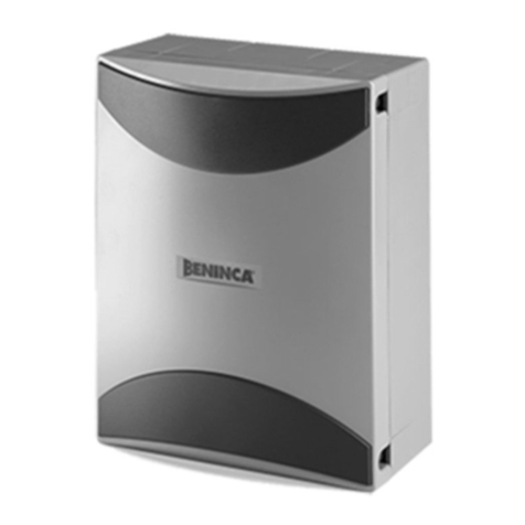
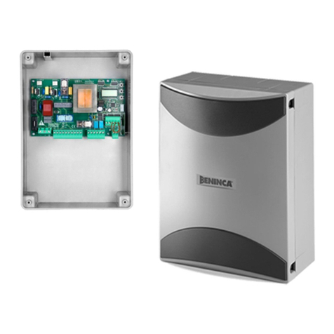
Beninca RI.10KI User manual
Other Beninca Control Unit manuals

Beninca
Beninca RI.624 User manual
Beninca
Beninca DA.AXE User manual
Beninca
Beninca KTE User manual

Beninca
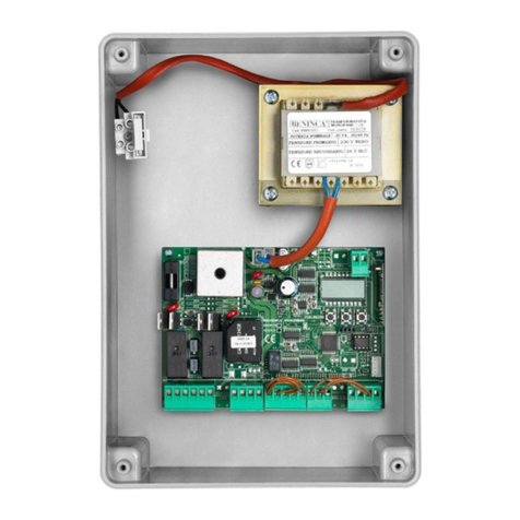
Beninca AU.TR User manual
Beninca
Beninca HEADY User manual

Beninca
Beninca DA.24V User manual
Beninca
Beninca MBE User manual
Beninca
Beninca Brain 24 MBE User manual
Beninca
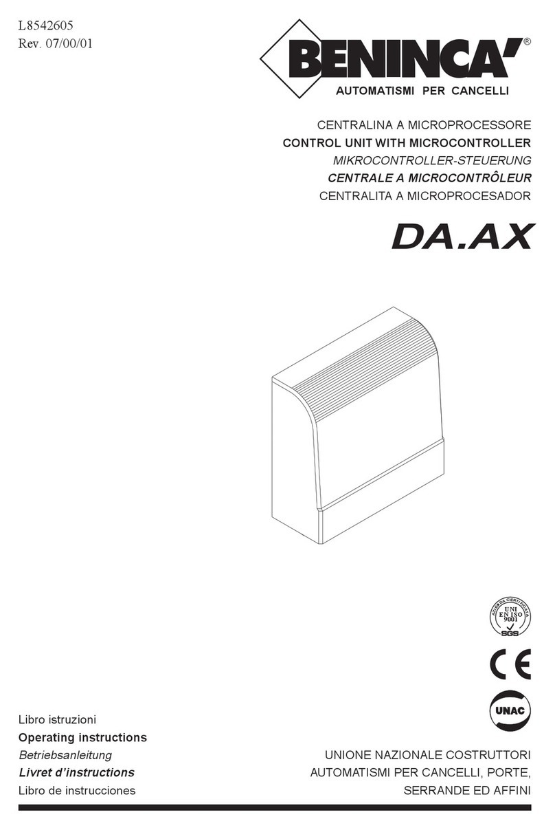
Beninca DA.AX User manual
Beninca
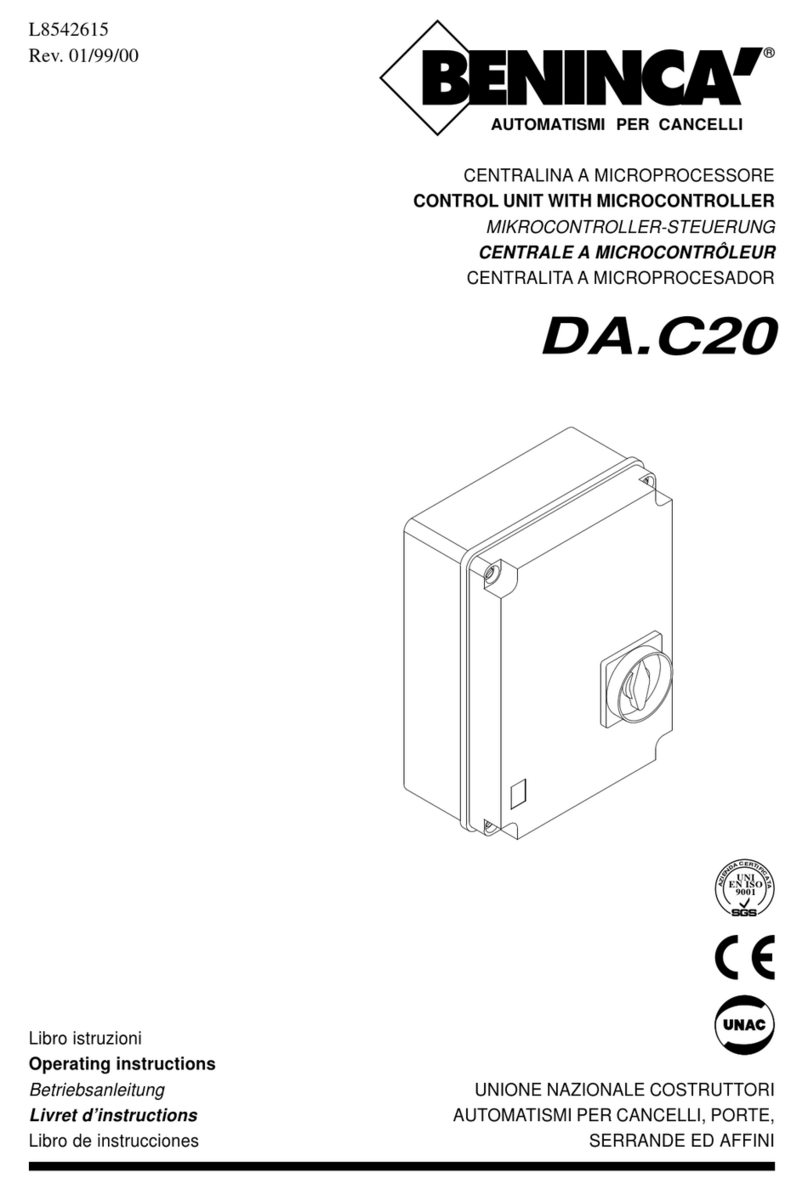
Beninca DA.C20 User manual
Beninca
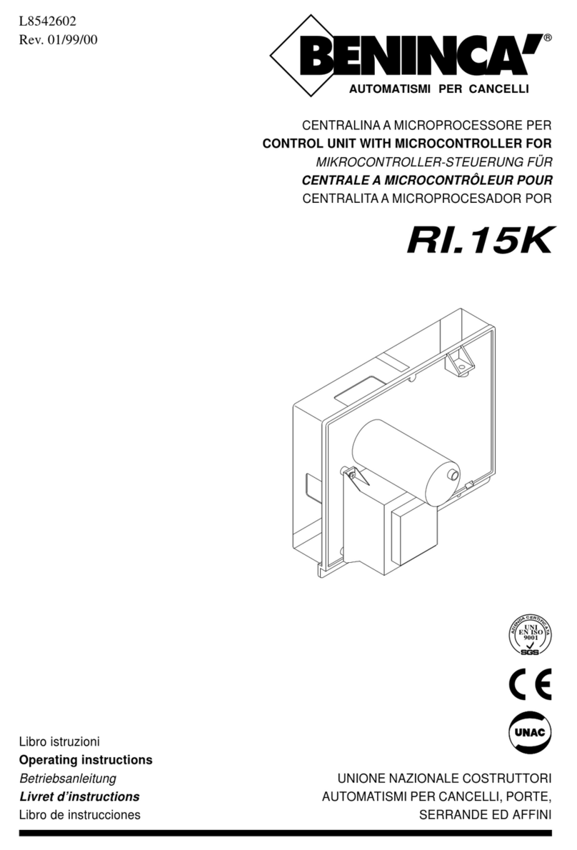
Beninca RI.15K User manual
Beninca
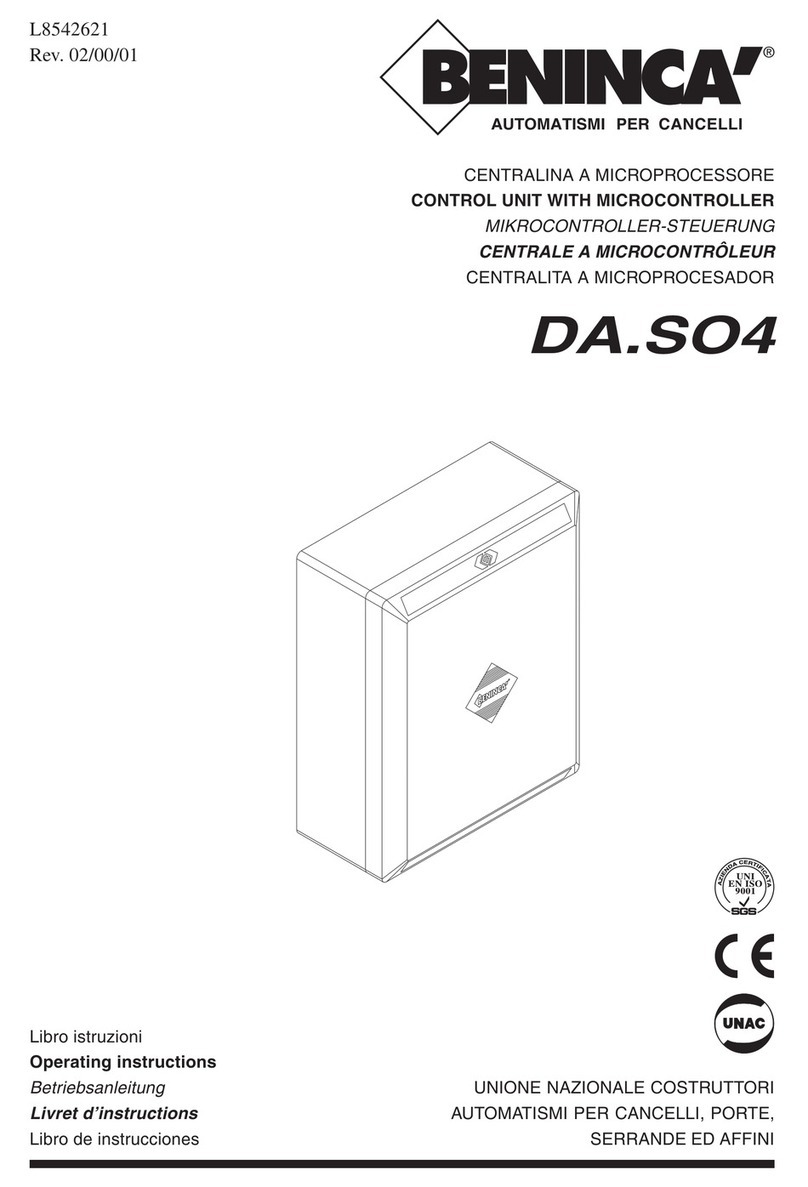
Beninca DA.SO4 User manual

Beninca
Beninca CELL.P User manual
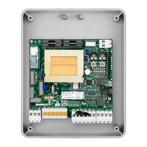
Beninca
Beninca CORE User manual
Beninca
Beninca CP.J3M User manual
Beninca
Beninca CP.BISON OTI User manual

Beninca
Beninca CORE User manual
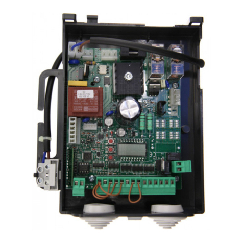
Beninca
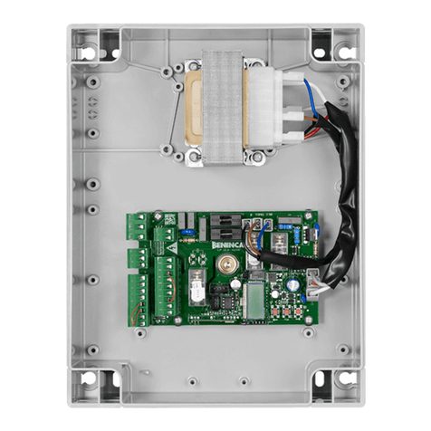
Beninca CP.B24ESA User manual
Beninca
Beninca LOGICA User manual

Beninca
Beninca CP.J3M User manual
Popular Control Unit manuals by other brands

Festo
Festo Compact Performance CP-FB6-E Brief description

Elo TouchSystems
Elo TouchSystems DMS-SA19P-EXTME Quick installation guide

JS Automation
JS Automation MPC3034A user manual

JAUDT
JAUDT SW GII 6406 Series Translation of the original operating instructions

Spektrum
Spektrum Air Module System manual

BOC Edwards
BOC Edwards Q Series instruction manual

KHADAS
KHADAS BT Magic quick start

Etherma
Etherma eNEXHO-IL Assembly and operating instructions

PMFoundations
PMFoundations Attenuverter Assembly guide

GEA
GEA VARIVENT Operating instruction

Walther Systemtechnik
Walther Systemtechnik VMS-05 Assembly instructions

Altronix
Altronix LINQ8PD Installation and programming manual
