5
- built-in gas pressure stabiliser
- NTC probe to control delivery temperature of the primary circuit
- NTC probe to control return temperature of the primary circuit
- device for separation and automatic purging of air
- 3-way valve with electric actuator
- pressure transducer
- hydrometer to visualise heating water pressure
- circulator anti-blocking device
- airtight combustion chamber
- electrically operated gas valve with dual shutter to command the burner
- external probe for thermoregulation
- self-diagnostics for signalling the cleaning of the primary circuit heat
exchanger
- circulator with variable speed (PWM= Pulse-Width Modulation)
- Range Rated - this means the boiler is equipped with a device that
adapts it to the heat requirements of the system, so the boiler output
can be adjusted according to the energy needs of the building
The safety devices of the appliance are:
- a water limit thermostat, to check for any overheating of the appliance
and thereby ensure the 100% safety of the system. To restore operation
if the limit thermostat is triggered, press the button on the right, beneath
the boiler shelf
- a flue gas probe - this intervenes (putting the boiler in safety stop mode)
if the temperature of the combustion products exceeds the maximum
operating temperature of the discharge pipes
- a safety valve at 3.5 bar
- a microprocessor check of probe continuity, with any faults indicated on
the display
- a drain-tap with float, for discharging the condensate and preventing the
leakage of flue gases
- a condensate level sensor - this intervenes by blocking the boiler if the
level of condensate in the heat exchanger exceeds the limit allowed
- a first level anti-freeze function (for installation area temperatures down
to -1°C), using the NTC heating probe
- a second level anti-freeze function (for installation area temperatures down
to -15°C), using the electric resistor kit that prevents the condensate in
the boiler from freezing
- diagnosis for absence of circulation (via the display of the temperatures
read by the delivery and return probes)
- a differential pressure switch allowing burner ignition if a minimum water
circulation is guaranteed in the primary circuit heat exchanger
- diagnosis for absence of water (via the pressure sensor)
- a flue gas safety evacuation system incorporated in the pneumatic
operation of the gas valve
- diagnosis for overtemperature (on both the delivery and return lines, with
dual probe - limit temperature 95°C -
- a fan check, via a Hall-effect revolutions counter: the rotation speed of
the fan is always monitored
The boiler is suitable for the connection of the following devices:
- an external 3-way valve
- a supplementary circulator
- an ambient thermostat or hourly timer
- an external probe for thermoregulation
- a remote control
- a safety thermostat for low temperature systems
- a remote thermostat or storage tank probe
Installation regulations
The installation must be carried out by qualified personnel, in compliance
with the following reference standards:
- UNI-CIG 7129
- UNI-CIG 7131
- UNI 11071
- CEI 64-8.
In addition, the local regulations must always be observed.
POSITION
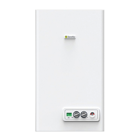
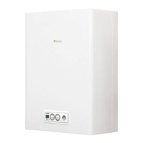
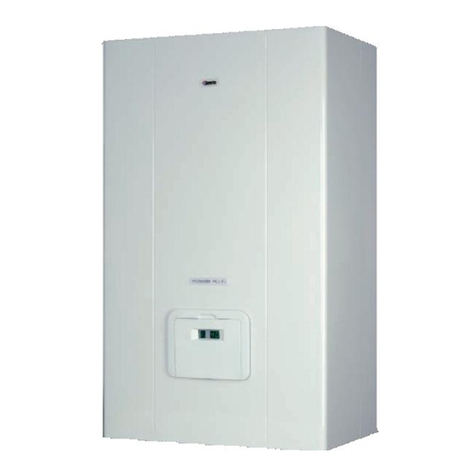
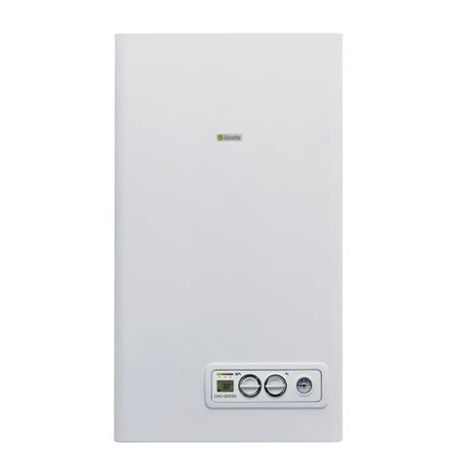
Power Green is a wall-mounted boiler for heating and for the production of
hot water.There are two categories, depending on the type of installation:
1) boiler type B23P-B53P - forced open installation, with discharge pipe
and pick-up of combustion air from the installation area. If the boiler is
not installed outdoors, air intake in the installation area is compulsory;
2) boiler type C13, C13x; C23; C33, C33x; C43, C43x; C53, C53x; C63,
C63x; C83, C83x; C93, C93x - appliance with airtight chamber, with
flue gas discharge pipe and pick-up of combustion air from outside.
It does not require an air intake point in the installation area.
This type MUST be installed using concentric pipes, or other types of
discharge designed for condensation boilers with an airtight chamber.
Power Green can be installed outdoors, in a partially protected place (i.e.
a place where the boiler is not exposed to direct contact or infiltration of
rain, snow or hail).
The boiler can operate in a temperature range from -15°C to +60°C.
For further details, refer to the “Anti-freeze system” section.
All the optional kits that can be connected to the boiler must be
protected on the basis of their electric protection level.
MINIMUM DISTANCES
To ensure access to the boiler for normal maintenance operations, respect
the minimum installation clearances envisaged.
For correct appliance positioning:
- do not place it on a cooker or other cooking device
- do not leave inflammable products in the room where the boiler is installed
- heat-sensitive walls (e.g. wooden walls) must be properly insulated
IMPORTANT
Before installation, wash every system piping carefully in order to remove
any residues that may impair the operation of the appliance.
Under the safety valve, install a water collecting funnel with the corresponding
discharge in the event of leaks due to the overpressure of the heating system.
Prior to ignition, make sure that the boiler is designed to operate with
the gas available;this can be checked by the wording on the packaging
and by the adhesive label indicating the gas type.
It is very important to highlight that in some cases the smoke pipes are under
pressure, so the joints of the various elements must be airtight.
ANTI-FREEZE SYSTEM
The boiler is fitted as standard with an automatic anti-freeze system that acti-
vates when the temperature of the water in the primary circuit falls below 6°C.
This system is always active, guaranteeing boiler protection down to an
installation area temperature of -1°C.
To take advantage of this protection (based on burner operation), the
boiler must be able to switch itself on; any lockout condition (for ex.
due to a lack of gas or electrical supply, or the intervention of a safety
device) therefore deactivates the protection.
Should it be necessary to protect the boiler for installation area tem-
peratures down to -15°C, you must use the specific anti-freeze kit
that prevents the condensate in the boiler from freezing.
To use the anti-freeze protection, an electrical\ supply is required;this
means that any blackout or disconnection will deactivate the protec-
tion.
The anti-freeze protection is also active when the boiler is on
standby.
In normal operation conditions, the boiler can protect itself against freezing.
In areas where temperatures may fall below 0°C, or when the machine is
left unpowered for long periods, you are advised to use a good quality anti-
freeze liquid in the primary circuit to avoid the risk of freezing if you do not
want to drain the heating system.
Carefully follow the manufacturer's instructions with regards not only the
percentage of anti-freeze liquid to be used for the minimum temperature
at which you want to keep the machine circuit, but also the duration and
disposal of the liquid itself. For the hot domestic water part, we recommend
you drain the circuit.
The boiler component materials are resistant to ethylene glycol based
anti-freeze liquids.
Eliminating the air from the heating circuit and boiler
During the initial installation phase, or in the event of extraordinary main-
tenance, you are advised to perform the following sequence of operations:
1. Use a CH11 spanner to open the manual air vent valve located on
the delivery pipe (Fig.33). Connect the tube (supplied with the boiler)
to the valve, so the water can be drained into an external container.
2. Turn on the tap to fill the system, and wait until water begins to seep
out of the valve.
3. Switch on the electricity supply to the boiler, leaving the gas tap turned
off.
4. Activate a heat request via the ambient thermostat or the remote
control panel, so that the 3-way valve goes into heating mode.
5. Activate a domestic water request by either turning on a tap (in the
case of instantaneous boilers) or via the storage tank thermostat (for
heating-only boilers connected to an external storage tank) for 30”
every minute so the 3-way valve passes from heating to domestic
water and vice versa about 10 times. In this situation, the boiler will
go into alarm mode due to the absence of gas, so it must be reset
every time this happens).
6. Carry on with the sequence until only water leaks out of the manual
air vent valve, and the air flow has stopped.
Close the manual air vent valve.
7. Check the system pressure level is correct (the ideal level is 2 bar).
8. Turn off the system filling tap.
9. Turn on the gas tap and ignite the boiler.
