10
DECLARATION OF
CONFORMITY
The machines described in
this manual comply with Di-
rectives 2006/42/EC; 2014/30/
UE; 2014/35/UE; 2011/65/UE,
Regulation (EC) 1935/2004.
The applicable harmonised
standards are: EN 12331 IPX2
Grade, EN 60204-1.
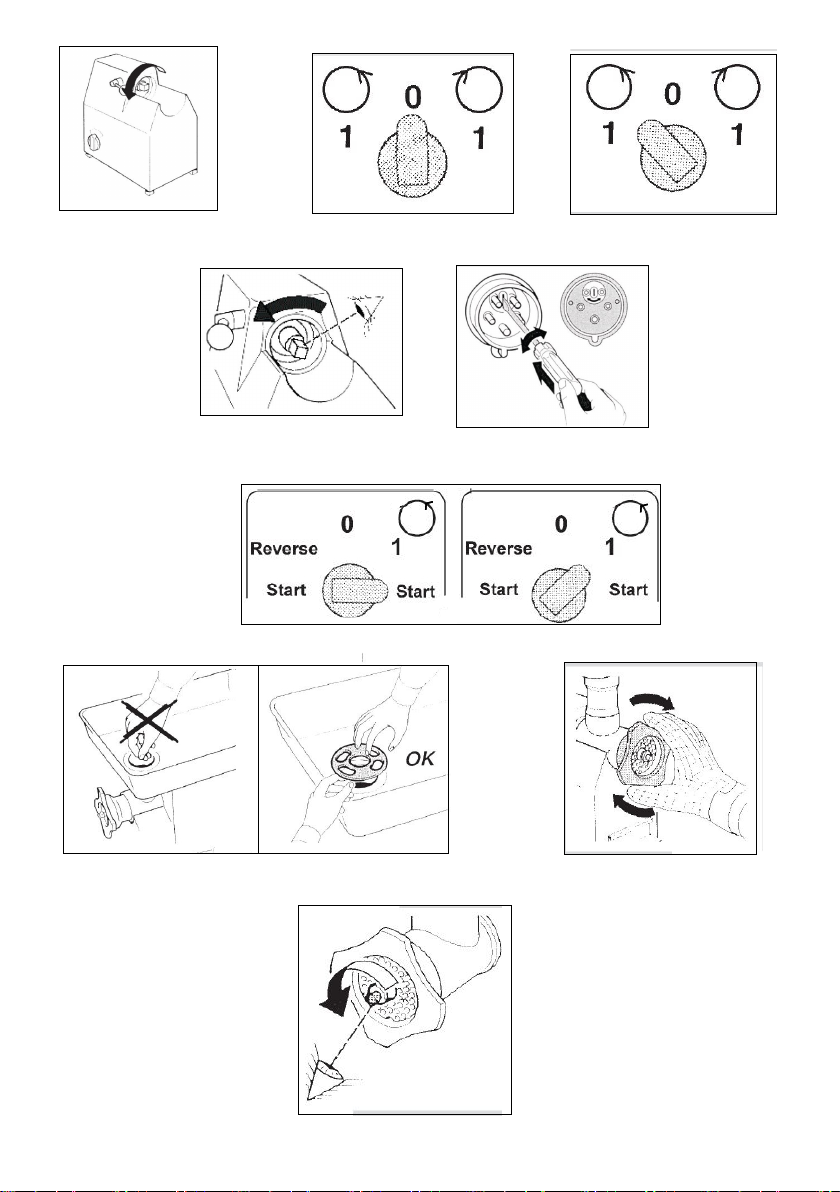
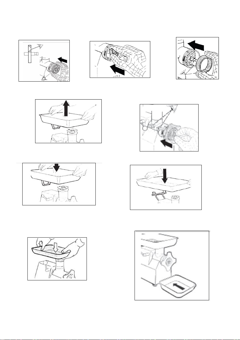
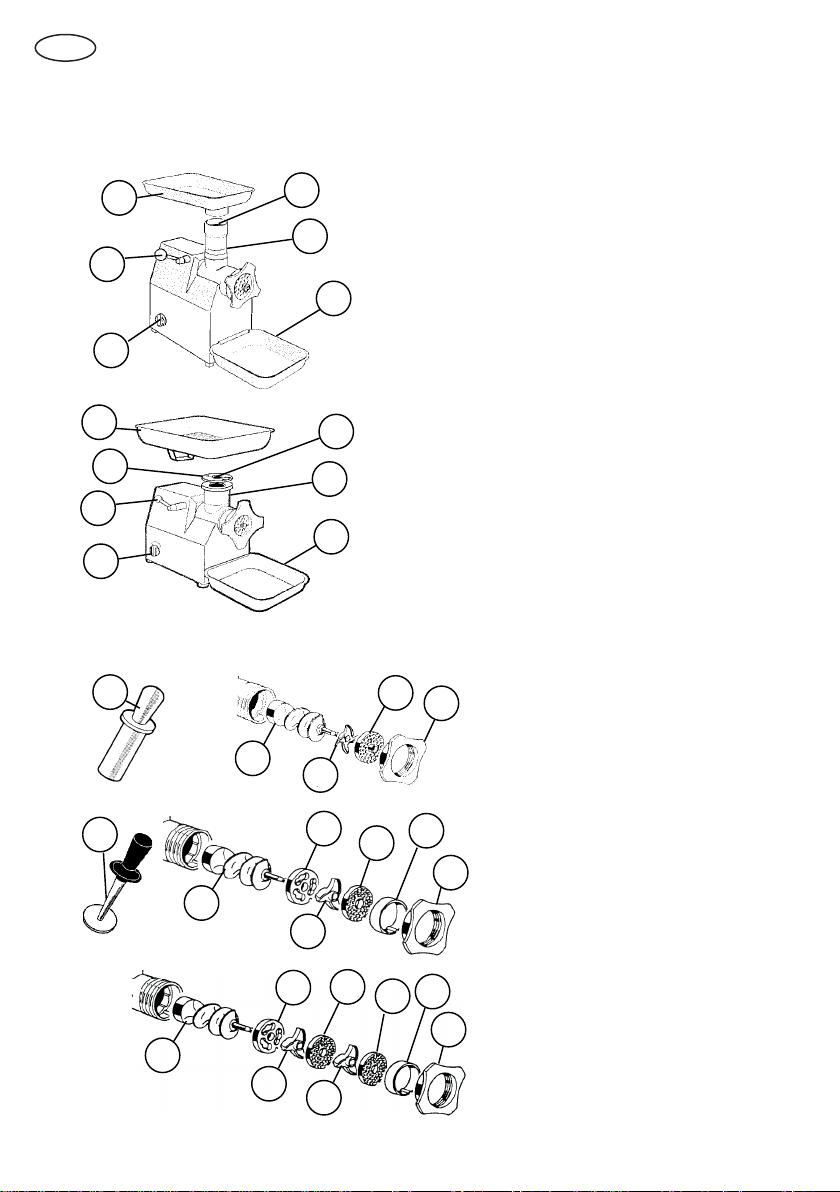
DESCRIPTION
Professional Meat Mincer
machines suitable for cut-
ting only the food products
of the types and within the
dimensional limits indicat-
ed in this manual. The main
parts of the machine are
shown in the general com-
ponent diagram reported in
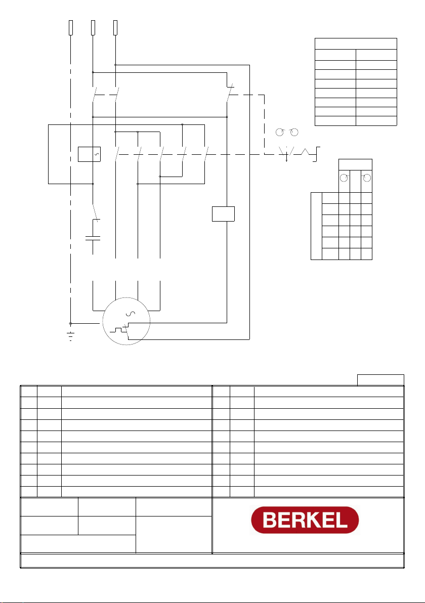
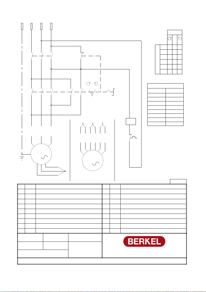
Fig. A. Electrical diagrams are
reported in Fig. B.
These appliances are intend-
ed to be used for commercial
applications, such as kitch-
ens in restaurants, canteens,
hospitals and in commercial
enterprises such as butchers
etc., but not for the contin-
uous production of food in
series.
The mincers are made of se-
lected materials that make
the machine particularly ro-
bust. The materials used in
their construction, anodized
aluminium and stainless
steel, have been selected in
accordance with the relevant
hygiene standards and main-
tain the machine in its origi-
nal condition over time.
-The high motor power pro-
vides high production capac-
ity
- No hand-arm vibration.
-Simple design with smooth
parts without sharp edges
provide for easy cleaning and
a practical use of the ma-
chine.
-The pusher is made in a
plastic material t for contact
with food- stuffs.
-The nal part of the cutting
unit is tted with an EDISON
screw thread according to
the USA NSF standard 8.
-Due to the particular con-
struction of the cutting unit
it is possible, in exceptional
circumstances, to place it in
a refrigerator. Such operation
does not exclude the neces-
sity of daily cleaning.
-The easy assembly and dis-
assembly of the components
simplify the use and mainte-
nance of the machine.
MACHINE IDENTIFICATION
In any communication with
the manufacturing company
always quote the serial num-
ber indicated on the identi-
cation label of the machine.
SAFETY
Pay attention to the follow-
ing basic safety precautions:
-read all the instructions be-
fore using the machine;
-operate the machine only if
properly trained and in per-
fect psycho-physical condi-
tions;
-the appliance can be used
by children under the age
of 8 and by people with re-
duced physical, sensory or
mental abilities, or without
experience or the necessary
knowledge, as long as they
are supervised or after they
have received instructions re-
lating to the safe use of the
appliance;
-cleaning and maintenance
intended to be carried out by
the user must not be carried
out by unsupervised chil-
dren;
-do not use the machine in
any way other than what in-
dicated in this manual;
-use the machines only in full
structural, mechanical and
system efciency;
-install the machine in con-
formity to the instructions
indicated in the “Installation”
section;
-install the machine in a lo-
cation out of the reach of
personnel unauthorized to
operate it;
-stay highly concentrated
when using the machine
and avoid any distraction
during use;
do not allow the machine
to be used by others who
have not read and fully un-
derstood the content of this
manual;
-do not wear baggy cloth-
ing or clothing with open
sleeves;
-do not allow anyone else,
other than the operator, to
approach during product
cutting operations;
-do not remove, cover or
modify the tags located on
the machine body and, in
case of damage of these, re-
place them promptly;
-do not remove and do not
modify or bypass any me-
chanical and electrical pro-
tective devices;
-mince only the permitted
products, do not attempt to