Berker 168 Series Service manual

Glass sensor
Glass sensor 1 – 4gang
Order no.: 168xx, 169xx
Operation and assembly instructions
1 Safety instructions
Installation and assembly of electrical devices may only be carried out by an electrician.
The glass sensor is not suitable for direct switching of mains voltage or low voltage.
Failure to observe these instructions may lead to damage to the device, fire, or other
hazards.
These instructions are an integral component of the product, and must be retained by the
end user.
2 Structure of the device
(1) (2)
(3)
Figure 1: Front view
(1) Sensor surfaces
(2) White LEDs
(3) Blue LED
97-09440-000
Page 1/9 03/2007
Glass sensor
(4)
(5) (6)
(7)
(8)
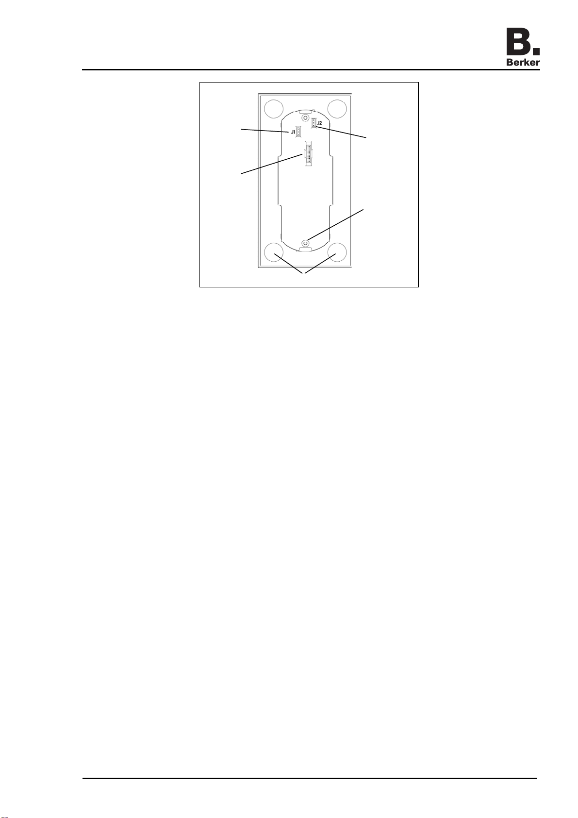
Figure 2: Rear view
(4) Connection for ribbon cable
(5) Jumper for selecting function of the blue LED
(6) Jumper for selecting function of the white LEDs
(7) Socket with setscrew and retaining pin
(8) Attachment locations for adhesive points
3 Function
The glass sensor is intended for connection to systems for controlling building installations.
The glass sensor controls lighting, shutters, etc. when the sensor surfaces are touched.
The functions which are available depend on the system that is connected. We strongly
recommend coordination between the user and the installer with regard to the function
assignments.
Integrated into the glass sensor are white LEDs and one blue LED for status indication.
The LEDs can be operated with their factory setting or controlled via the connected system, if
this is allowed by the system.
The glass sensor must be connected to an adapter using the supplied ribbon cable.
The adapter can be used to connect interfaces to the systems KNX/EIB or radio bus, or supply
voltage from 8 to 30 V=. Other systems, such as relay circuits, can also be connected using an
adapter within the limits of the technical specifications.
4 Operation
The operation of functions must be set individually for each glass sensor depending on the
system. Two operating modes are typical:
Single-surface operation:
Switching lighting, etc. on/off and dimming it brighter/darker is carried out in toggle mode, i. e.
alternately by repeated touching of the sensor surface.
Two-surface operation:
Two opposite sensor surfaces form a functional pair. For example, touching the left-hand
surface switches/dims lighting on/makes it brighter, touching the right-hand surface switches it
off/ makes it darker.
97-09440-000
Page 2/9 03/2007

Glass sensor
Operating the glass sensor
Touch a sensor surface (Figure 1, 1).
The underlying function is executed.
The actuation pulse is active for as long as the surface is touched. Depending on the
function, short and long touches can trigger different actions, e. g. switching/dimming.
5 Information for electricians
5.1Assembly and electrical connections
CAUTION!
Risk of destruction of the sensor or the connected system.
Fault voltages may occur when working under voltage.
Isolate from voltage before connecting the installation environment.
Mounting requirements
An adapter is required in order to connect the glass sensor to the building installations.
The choice of adapter depends on the specific interface and the connected installation system.
For instructions on connecting the adapter to the installation environment, please consult the
operating and assembly instructions for the adapter.
The user must provide a supply voltage of from 8 to 30 V= for the glass sensor.
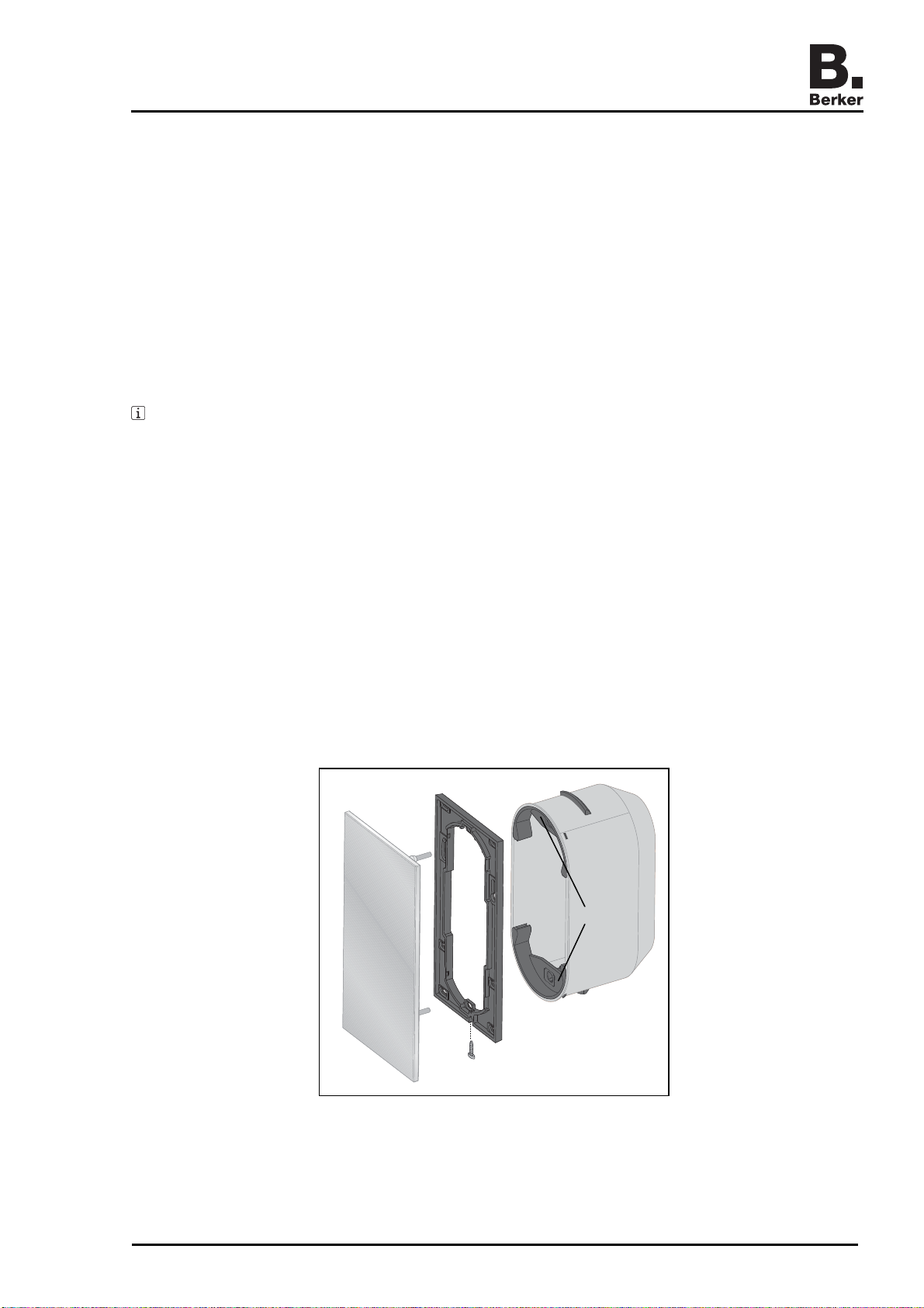
(11)(12)
(9)
(10)
Figure 3
Berker recommends mounting the glass sensor on a special wall box (Figure 3, 10). This wall
box 2gang for glass sensors provides enough room to house the adapter and the necessary
interfaces. The glass sensor is fastened to the wall box using a locking device. With deep-set
wall boxes, surface adjustment of up to 20 mm is possible by adjusting the retaining pins
(Figure 3, 12) on the setscrews (Figure 3, 11).
For mounting on smooth surfaces, adhesive points are included with the glass sensor; these
can be used for additional fastening of the glass plate after it is aligned.
97-09440-000
Page 3/9 03/2007
Glass sensor
Mounting on 1gang flush-mounted boxes is possible. This involves more installation work,
because less installation space is available. In addition, the glass sensor must be fastened to
the wall using the supplied adapter ring.
The adapter ring (Figure 3, 9) must be used:
–for additional anti-dismantling protection
–for visual reasons, so that the distance from the wall will create a shadow gap
–for mounting on 1gang flush-mounted boxes
Setting the operating mode of the LEDs using jumpers
Factory setting of the blue LED:
Permanent indication of readiness for operation
The blue LED is lit when operating voltage is connected.
Factory setting of the white LEDs:
Indication of actuation
The corresponding LED is lit as long as a touch on the sensor surface is detected.
The LEDs can be controlled via the connected system. The white LEDs can be set e. g. as
status LEDs that indicate the operating state of the respective connected loads.
The blue LED can be parameterised as an orientation light that is lit at night, or as an operation
LED that is not lit at night so as not to be annoying.
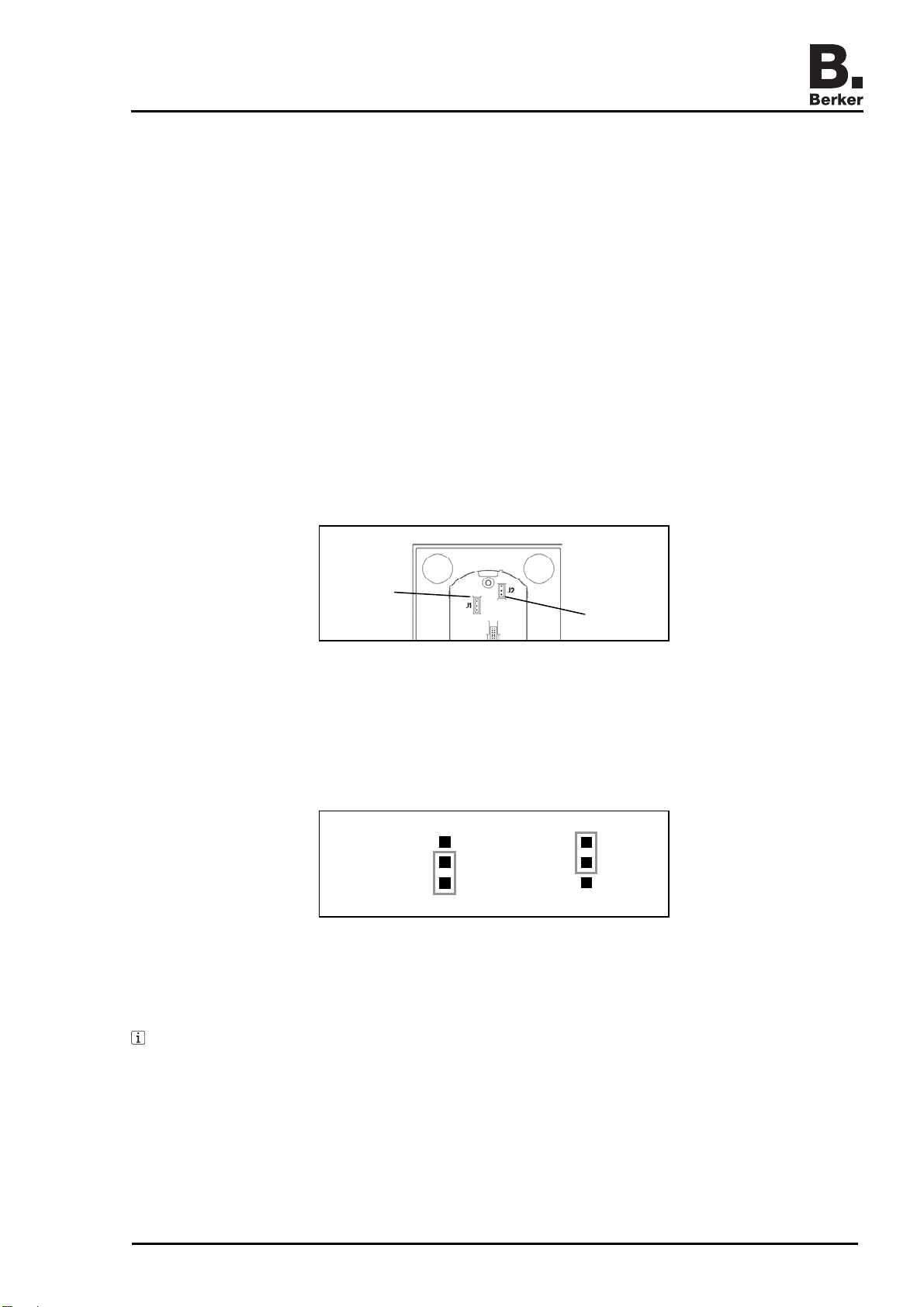
(5)
(6)
Figure 4
To activate the LEDs via the connected system, the corresponding jumper (Figure 4) on the
back of the glass sensor must be adjusted.
J1 = Jumper 1 (Figure 4, 5) for operating mode of the blue LED
J2 = Jumper 2 (Figure 4, 6) for operating mode of the white LEDs
S
W
Figure 5
Move the corresponding jumper from the factory setting (Figure 5, W) to system control
(Figure 5, S).
If the jumpers for the LEDs are not in the factory setting position and there is no activation
via the connected system, then the LEDs remain unlit.
Preparing the glass sensor for mounting on a smooth surface
The adhesive points prevent the glass sensor from shifting on smooth surfaces.
Clean the attachment locations for the adhesive points on the back of the glass sensor
(Figure 2, 8).
Peel the adhesive points off of their backing and apply them to the four attachment points.
Clean the mounting surface.
97-09440-000
Page 4/9 03/2007

Glass sensor
Before mounting the glass sensor, peel the protective foil off of the adhesive points.
Before completing mounting, align the glass sensor and press on the areas over the
adhesive points to fix it in place.
Connecting the glass sensor and mounting it on a wall box
The necessary adapter must be connected to a supply voltage and an interface. The wall box
2gang for the glass sensor is mounted at the installation location.
x
15 mm+ x
(11)(12) (13)
Figure 6
If necessary, measure the required surface adjustment (Figure 6, x). Screw the retaining
pins (Figure 6, 12) on the setscrews (Figure 6, 11) out by the surface adjustment x so that
they have a distance of 15 mm + x from the socket for the setscrews.
Set the surface adjustment precisely so that after mounting the glass sensor is firmly in
contact with the wall.
Connect the glass sensor to the adapter being used by means of the supplied ribbon cable.
Do this by inserting the plugs into the slots provided for that purpose in the glass sensor
(Figure 2, 4) and the adapter.
The electrical connection to the adapter has been established.
Place the adapter, connecting cables and if necessary system interfaces in the wall box.
97-09440-000
Page 5/9 03/2007
Glass sensor
Insert the setscrews (Figure 6, 11) of the glass sensor into the clamp springs (Figure 6, 13)
and press in until the retaining pins (Figure 6, 12) engage noticeably.
Connecting the glass sensor and mounting it on a wall box with an adapter ring
The necessary adapter must be connected to a supply voltage and an interface. The wall box
2gang for the glass sensor is mounted at the installation location.
Snap the adapter ring onto the back of the glass sensor. The marking TOP on the inside of
the adapter ring must be at the top.
Adjust the positions of the retaining pins. Screw the retaining pins on the setscrews out by
the thickness of the adapter ring (5 mm).
If necessary, measure the required surface adjustment (Figure 6, x). Additionally screw
the retaining pins (Figure 6, 12) on the setscrews (Figure 6, 11) out by the surface
adjustment x so that they have a distance of 20 mm + x from the socket for the setscrews.
Set the surface adjustment precisely so that after mounting the glass sensor is firmly in
contact with the wall.
Connect the glass sensor to the adapter being used by means of the supplied ribbon cable.
Do this by inserting the plugs into the slots provided for that purpose in the glass sensor
(Figure 2, 4) and the adapter.
The electrical connection to the adapter has been established.
Place the adapter, connecting cables and if necessary system interfaces in the wall box.
Insert the setscrews (Figure 6, 11) of the glass sensor into the clamp springs (Figure 6, 13)
and press in until the retaining pins (Figure 6, 12) engage noticeably.
Connecting the glass sensor and mounting it with additional anti-dismantling protection
For additional anti-dismantling protection the glass sensor is connected to the adapter ring by
means of a locking screw at the bottom of the adapter ring. For this reason, the adapter ring
must be screwed to the wall box or the wall ahead of time.
The necessary adapter must be connected to a supply voltage and an interface. The wall box
2gang for the glass sensor is mounted at the installation location.
(14)
(15)
(16)
Figure 7
97-09440-000
Page 6/9 03/2007
Glass sensor
If the adapter ring is to be screwed to the wall box, pry the clamp spring supports
(Figure 7, 15) out of the wall box.
This exposes the screw holes in the wall box.
Align the adapter ring (Figure 7, 14) and screw it to the wall box. The marking TOP on the
inside of the adapter ring must be at the top. For fastening to the wall with screws, use the
supplied set of screws and wall plugs.
The adapter ring has been fastened at the installation location.
Connect the glass sensor to the adapter being used by means of the supplied ribbon cable.
Do this by inserting the plugs into the slots provided for that purpose in the glass sensor
(Figure 2, 4) and the adapter.
The electrical connection to the adapter has been established.
Place the adapter, connecting cables and if necessary system interfaces in the wall box.
Push the glass sensor onto the adapter ring until it engages.
The engagement on the adapter ring is only a preliminary fastening. Additional fastening
using the anti-dismantling protection is necessary for operation.
Tighten the screw (Figure 7, 16) at the bottom of the adapter ring. Use a Pozidrive-type
Phillips screwdriver, size 0.
Additional anti-dismantling protection has been provided.
Connecting the glass sensor and mounting it on a 1gang flush-mounted box
The necessary adapter must be connected to a supply voltage and an interface. The flush-
mounted box is mounted at the installation location.
Screw the setscrews (Figure 6, 11) out of the sockets on the back of the glass sensor.
The head end of the setscrews has a socket for an Allen key, width 1.5 mm.
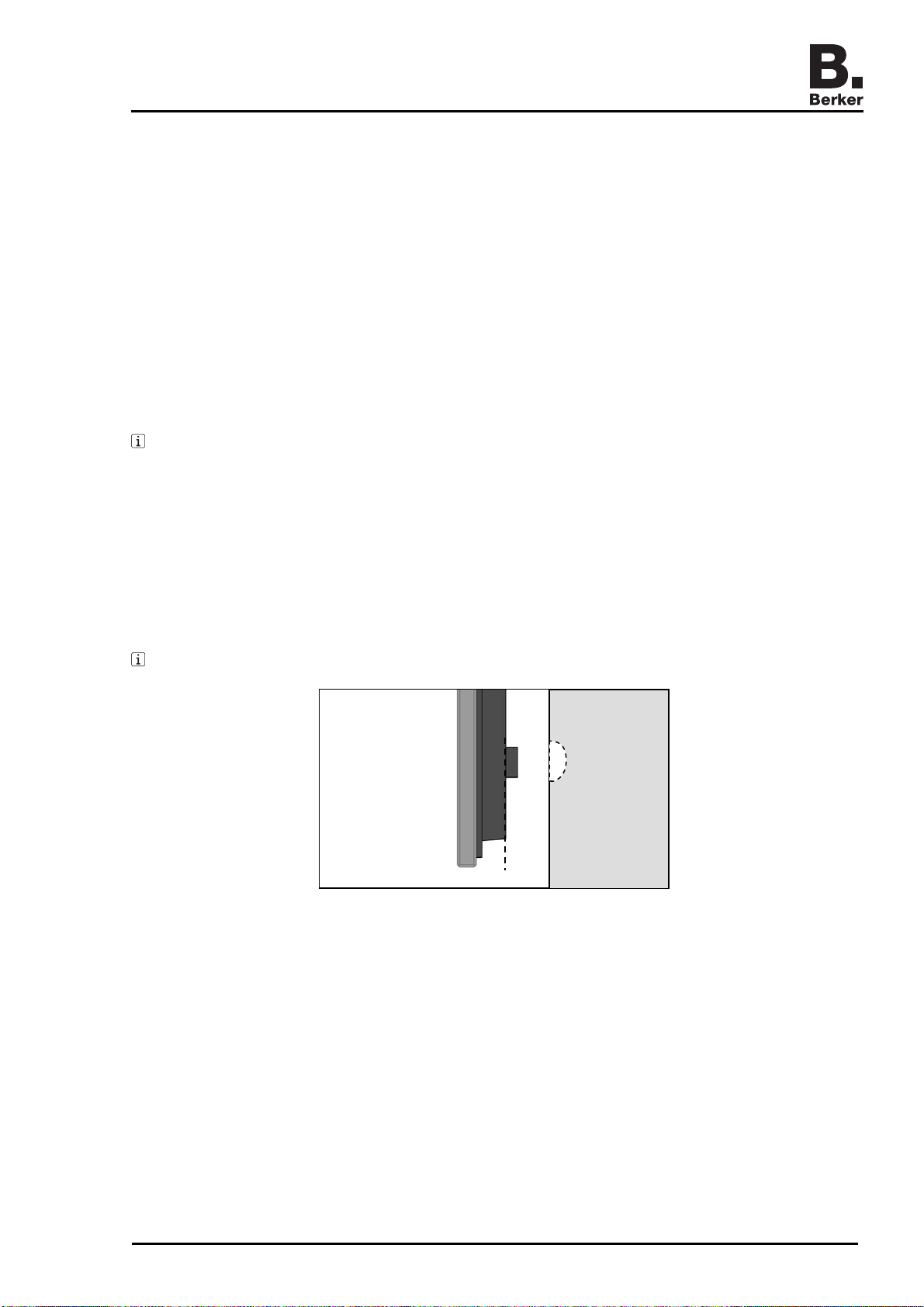
(18)
(17)
Figure 8
Remove the lower socket for the setscrew (Figure 8, 17) or if necessary make a recess in
the wall (Figure 8, 18) that can hold the socket.
Align the adapter ring (Figure 7, 14) and screw it to the wall box and the wall. The marking
TOP on the inside of the adapter ring must be at the top. Use the supplied set of screws
and wall plugs.
The adapter ring has been fastened at the installation location.
Connect the glass sensor to the adapter being used by means of the supplied ribbon cable.
Do this by inserting the plugs into the slots provided for that purpose in the glass sensor
(Figure 2, 4) and the adapter.
The electrical connection to the adapter has been established.
Place the adapter, connecting cables and if necessary system interfaces in the wall box.
97-09440-000
Page 7/9 03/2007

Glass sensor
Push the glass sensor onto the adapter ring until it engages.
The engagement on the adapter ring is only a preliminary fastening. Additional fastening
using the anti-dismantling protection is necessary for operation.
Tighten the screw (Figure 7, 16) at the bottom of the adapter ring. Use a Pozidrive-type
Phillips screwdriver, size 0.
Additional anti-dismantling protection has been provided.
Dismantling the glass sensor
If necessary remove the screw (Figure 7, 16) at the bottom of the adapter ring. Use a
Pozidrive-type Phillips screwdriver, size 0.
The additional anti-dismantling protection has been removed.
Press the supplied dismantling tool against the centre of the glass sensor.
Using the dismantling tool, pull the glass sensor evenly out of the clamp springs.
Pull the ribbon cable out of the glass sensor.
The glass sensor has been dismantled.
Putting the glass sensor into operation
The installation system has been made ready for operation. Mains voltage is connected to the
system devices.
Switch on supply voltage for the glass sensor.
The glass sensor is ready for operation.
6 Appendix
6.1Technical data
Operating voltage 8 ... 30 V=
Current consumption in operation 1gang, approx. 20 mA
2gang, approx. 26 mA
3gang, approx. 32 mA
4gang, approx. 38 mA
Switching voltage max. 30 V=
Switching current with
- KNX/EIB adapter 2 x 8gang max. 1 mA
- adapter KNX/EIB, relay max. 10 mA
- radio adapter max. 1 mA
LED input voltage max. 5 V=
LED input current max. 1 mA
Surface adjustment up to 20 mm
6.2Troubleshooting
Surface adjustment
Cause: Retaining pins incorrectly adjusted on the setscrews.
Re-measure setting of the retaining pin and correct if necessary.
Glass sensor shifts on the wall
Cause: Smooth surface provides insufficient purchase.
Use the adhesive points for mounting (prepare glass sensor for mounting on smooth
surface).
97-09440-000
Page 8/9 03/2007

Glass sensor
97-09440-000
Page 9/9 03/2007
Glass sensor does not respond to operator control
Cause 1: The connection from the glass sensor to the adapter is faulty.
Check that the ribbon cable is properly seated and correct if necessary.
Cause 2: The glass sensor has no voltage supply.
Check the voltage supply and re-establish if necessary.
Cause 3: The polarity of the voltage supply connection is reversed.
Switch polarity of the voltage supply.
Cause 4: Condensation moisture on the surface of the glass sensor due to a temperature
difference from the ambient temperature.
Remove condensation moisture. If necessary wait for the temperature to equalise.
Glass sensor cannot be pulled off
Cause: Additional anti-dismantling protection has been provided.
Remove screw at the bottom of the adapter ring (dismantle the glass sensor).
6.3Accessories
Wall box 2gang for glass sensor 1870
Universal adapter 7590 00 32
KNX/EIB adapter 2 x 8gang 7590 00 31
6.4Warranty
We reserve the right to make technical and formal changes to the product in the interest of
technical progress.
Our products are under guarantee within the scope of the statutory provisions.
If you have a warranty claim, please contact the point of sale or ship the device postage free
with a description of the fault to the appropriate regional representative.
Berker GmbH & Co. KG
Klagebach 38
58579 Schalksmühle/Germany
Phone: + 49 (0) 23 55/90 5-0
Fax: + 49 (0) 23 55/90 5-111
www.berker.com
This manual suits for next models
1
Table of contents
Other Berker Accessories manuals


Popular Accessories manuals by other brands

 instruction manual")


Isotra
Isotra VERANDA HRV52 MEASUREMENT AND ASSEMBLY MANUAL

Baumer
Baumer UNAR 18P6912/S14G manual

LumaSense technologies
LumaSense technologies IN 2000 Operation manual

Tork Winch
Tork Winch TW 2000 installation instructions

E+E Elektronik
E+E Elektronik EE610 user manual

Lenovo
Lenovo Active Pen 3 LP-251 Safety, warranty & quick start guide