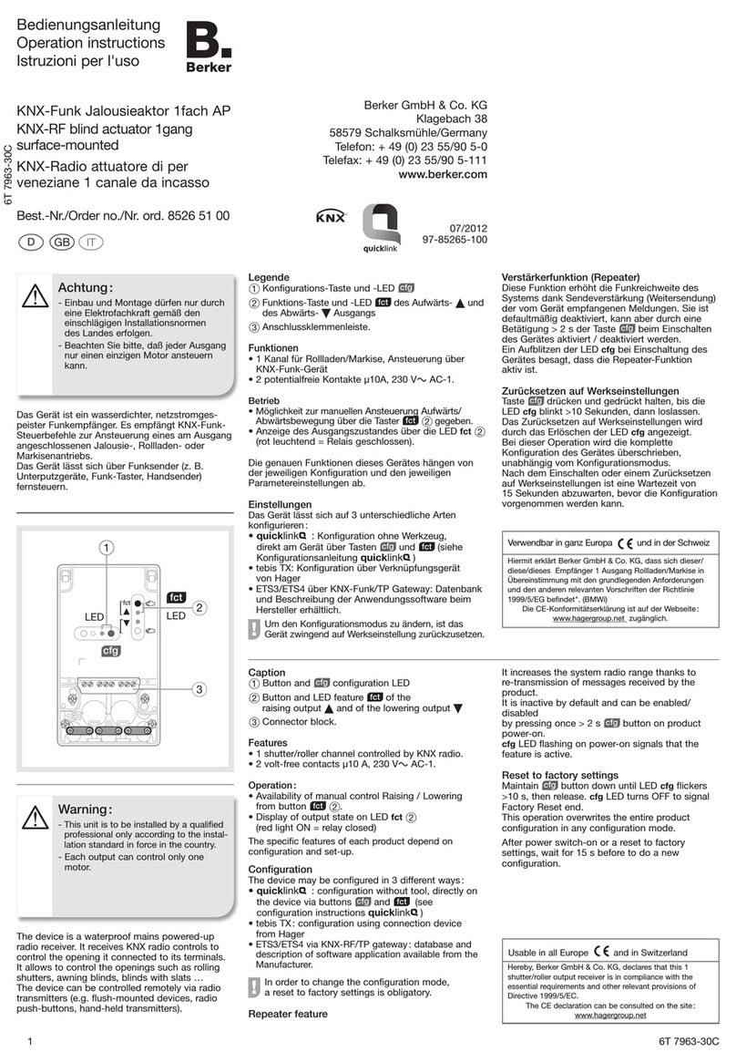
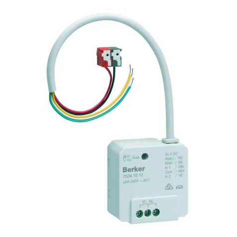
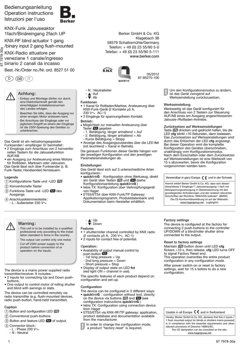
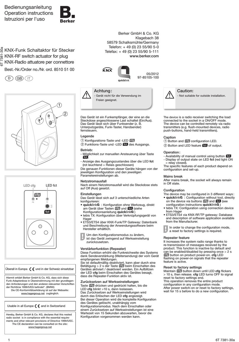
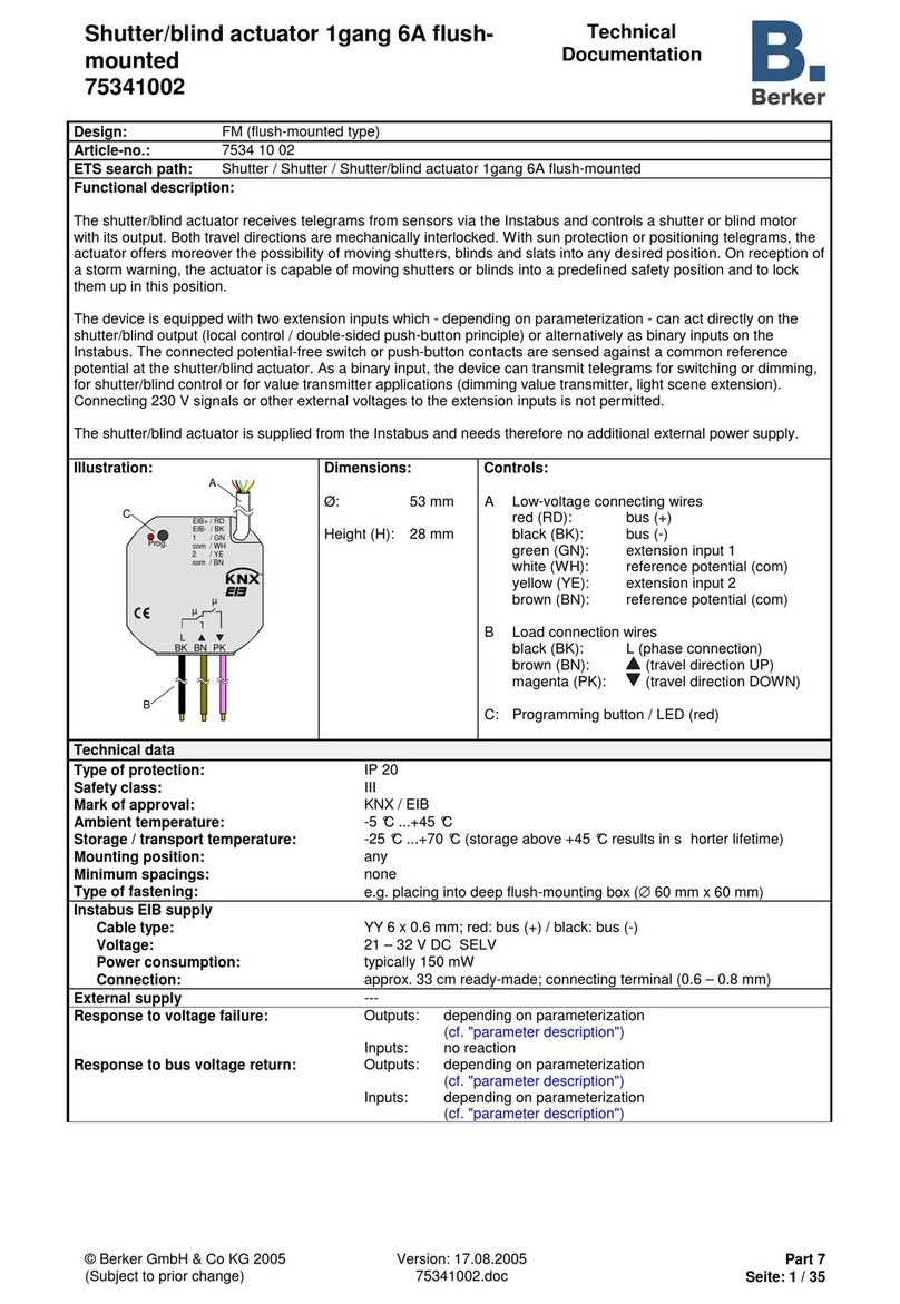
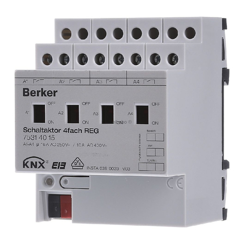
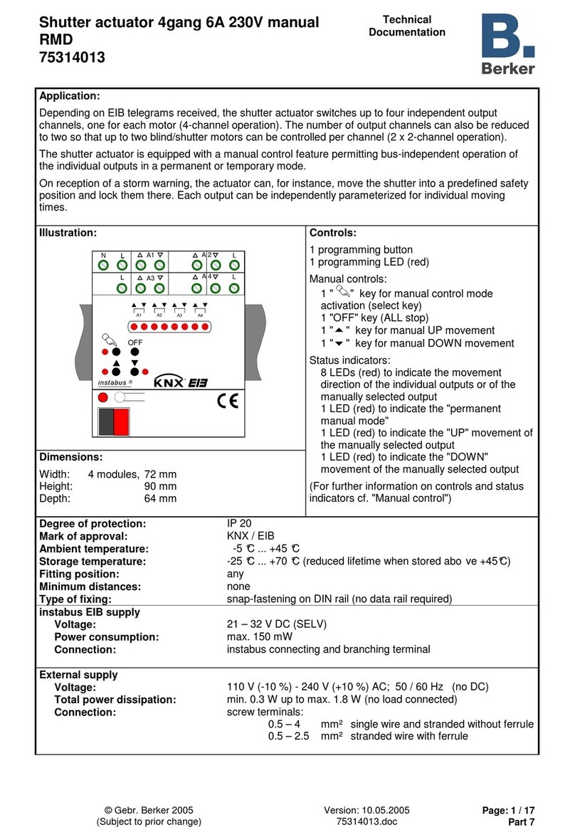
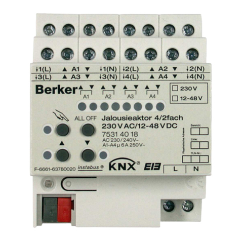
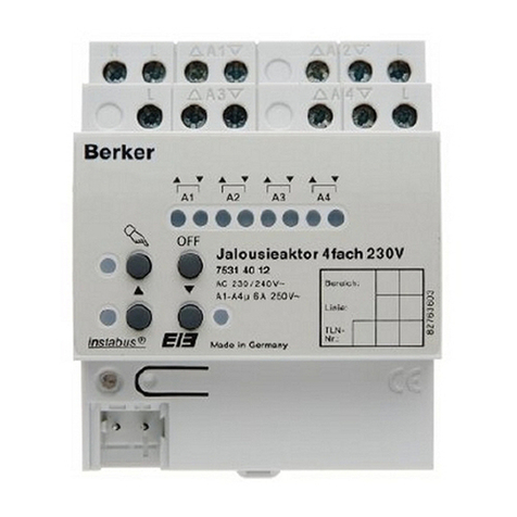
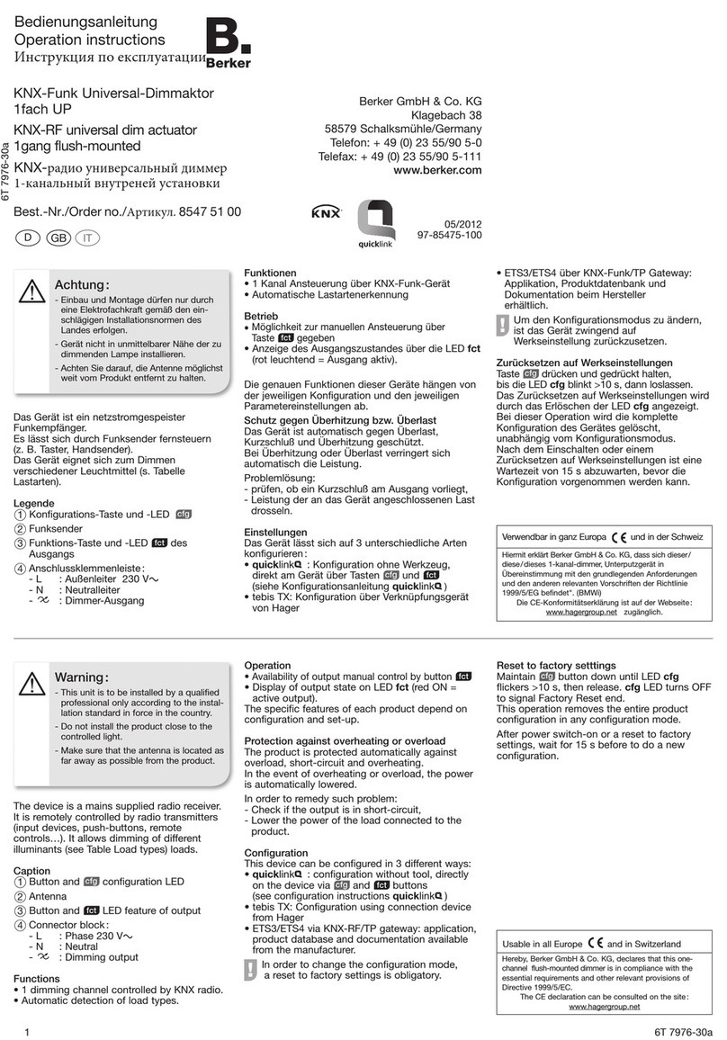
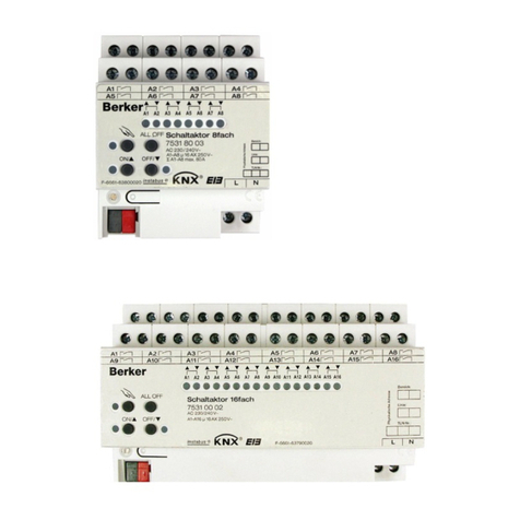
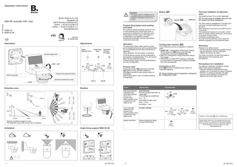
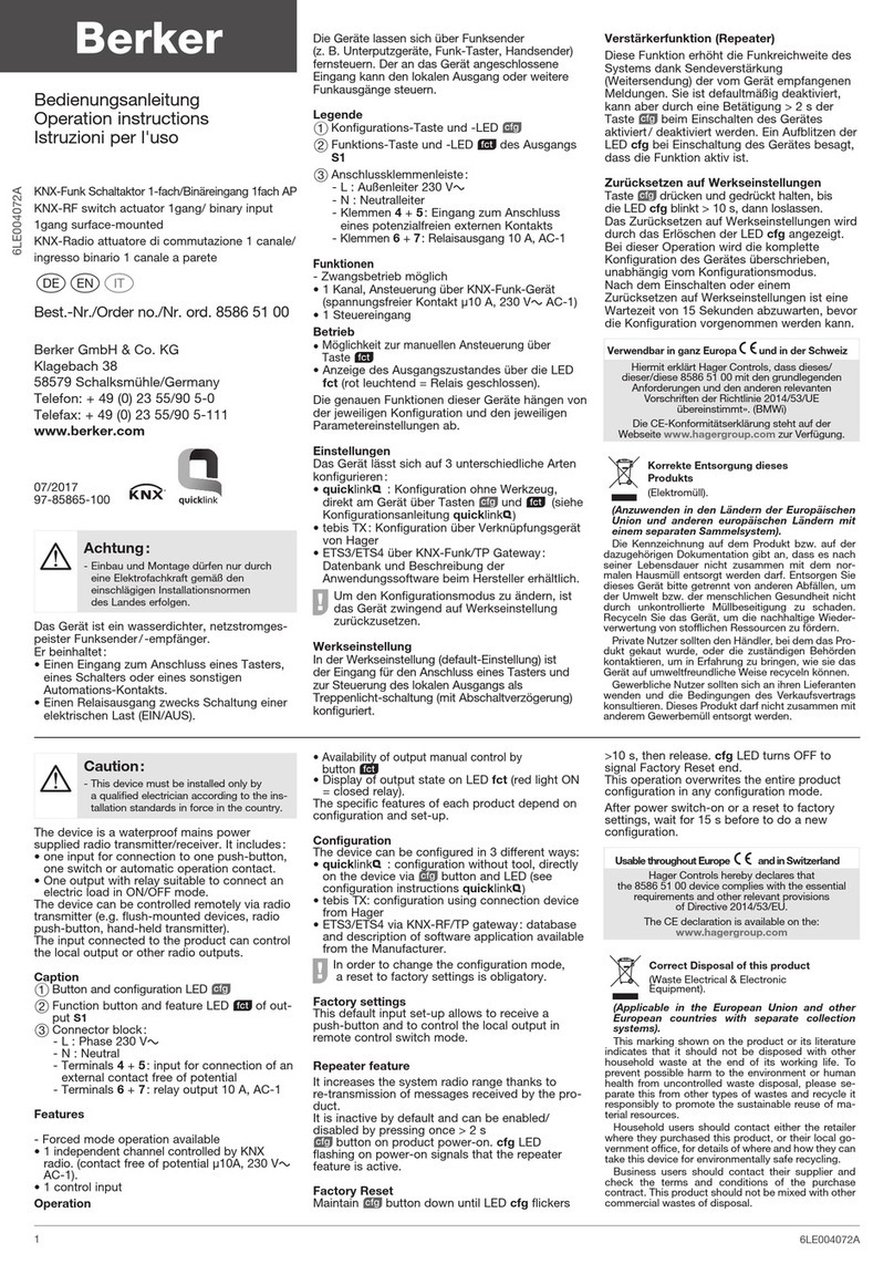
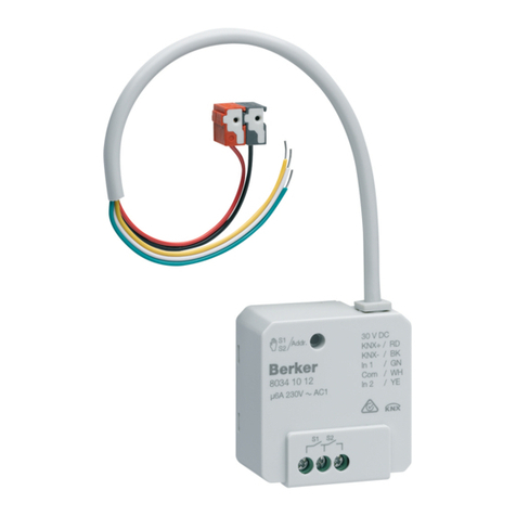
Set 8536 51 99 Pre-configured
(ON/O switch function)
1. Clear the previous pre-configured function
if Set 8536 51 99 is used (see configuration
instructions quicklink&)
2. Set the potentiometer to position
3. Configure the "timer"
(see configuration instructions quicklink&)
1detector 8536 51 00
+
1 receiver
Recommended configuration :
1. Set the potentiometer to a value different
from
2. Configure ON/O switch function (see
configuration instructions quicklink&)
Set 8536 51 99
+
1 or several
other receivers
In order to have the same delay on each receiver:
1. Set the potentiometer to a value different
from
2. Configure the ON/O switch function (see
configuration instructions quicklink&)on other
receivers
In order to have a different delay on each receiver :
1. Clear the previous pre-configured function if
Set 8536 51 99 is used (See the Configuration
Instructions)
2. Set the potentiometer to position
3. Configure the "timer" function
(see configuration instructions quicklink&)
1detector 8536 51 00
+
several receivers
Several detectors
8536 51 00
+
1or several
receivers
Not recommended (conflict of delays) 1. Clear the previous pre-configured function if
Set 8536 51 99 is used (See the Configuration
Instructions)
2. Set the potentiometer to position on both
detectors.
3. Configure the "timer" function
(see configuration instructions quicklink&)
on each receiver
Set 8536 51 99
or
1 detector 8536 51 00
+
1 or several
transmitters
other than detectors
+
1 or several
receivers
Timer function being not used on the other
transmitter(s) :
1. Set the potentiometer to a value different
from
2. Configure the other transmitter(s)
(see configuration instructions quicklink&)
with a function other than timer
Timer function used on the other transmitters :
1. Clear the previous pre-configured function if
Set 8536 51 99 is used (See the Configuration
Instructions)
2. Set the potentiometer to position
3. Configure the "timer" function
(see configuration instructions quicklink&) on
each receiver for each transmitter involved
Note : During configuration of a detector, Step 2 of the configuration instructions quicklink&shall be ignored.
TRO BLESHOOTING...
PROBLEM CA SES SOL TIONS
nwanted lamp
switch on.
- Permanent heat source is active in the detection area (trees, bushes
shook by wind or presence of dogs, cats in the detection area).
- The detector is located on top a ventilation grill.
- Limit detector’s range by adjusting its inclination or by fitting
shuttering blades to the lens, or by lowering sensitivity using the
adjustment knob.
- Move the detector to another location.
The range of
the detector is
too narrow.
- Detector’s installation height is not suitable (too high or too low).
- Sloppy ground.
- Modify installation height (2.5 m is optimal).
- Adjust detector’s direction.
Moving vehicle or
person is not
detected.
- Vehicle’s motor is not enough yet (heat radiation is too weak).
- People move forwards in front of detector.
- Detector energy too low.
- Install the detector in such a way that objects move within the area
in transverse direction.
- Replace power cells.
Technical specifications
Electrical specifications
Power Supply : 3 x 1,5 V AAA
Operational characteristics
Dimensions (L x w x h) : 153 x 91 x 130 mm
Luminosity threshold : 5 … 1000 Lux
ixed time: 30 s … 15 min
Sensitivity : min. 20%, max. 100%
Limiting the detection zone : adjustable shutters
supplied
Transmission frequency : 868.3 MHz
Transmitter duty cycle : 1%
Receiver category : II
Range : 100 m on open field
ixing accessories: corner support
(sold separately) Order no. 8590 02 00
Environment
Operating temperature : -20 … +55 °C
Storage temperature : -20 … +60 °C
IK : 04
Protection class : IP55
Resistance to fire : 750 °C
Standards : EN 60950-1 ; EN 301489-3 ;
EN 300220-2 ; EN 50491-3
(Please refer to Detector User's Instructions).
Other devices can be added to the kit.
Various configuration options are available
When a detector is associated with a receiver, only 2
functions are available, depending on potentiometer’s
position :
- (Red/Green LED) or timer (Red flashing
LED) according to the case
-Delete (LED is O )
The receiver will offer only the function set by the
potentiometer.
When a product is factory reset,
pre-configuration is removed.
It should then be configured again.
4 6T 7972-31a
OCOM 113657

