Beta RR 2T 2013 User manual


1GB
RR 250 - 300 2T
Thanks for you preference, and have a good time! This hand-
book contains the information you need to properly operate and
maintain your motorcycle.
The data and specifications provided in this manual does not constitute an
engagement on the part of BETAMOTOR S.p.A. BETAMOTOR reserves the
right to make any changes and improvements to its models at any moment
and without notice.

2
GB
IMPORTANT
We recommend you to check all the tightenings after the first one
or two hours’ ride over rough ground. Special attention should
be paid to the following parts:
•rear sprocket
•ensure that the footrests are properly fixed
•front/rear brake levers/calipers/discs
•check that the plastics are properly fastened
•engine bolts
•shock absorber bolts/swingarm
•wheel hubs/spokes
•rear frame
•pipe connections
•tensioning the chain
IMPORTANT
For any servicing requirements, please get in contact with Beta-
motor’s authorized service network.

CONTENTS
3GB
Operating instructions.............................................................................. 5
Ecologic guide....................................................................................... 5
Riding safety.......................................................................................... 6
CHAPTER 1 GENERAL INFORMATION.............................................. 7
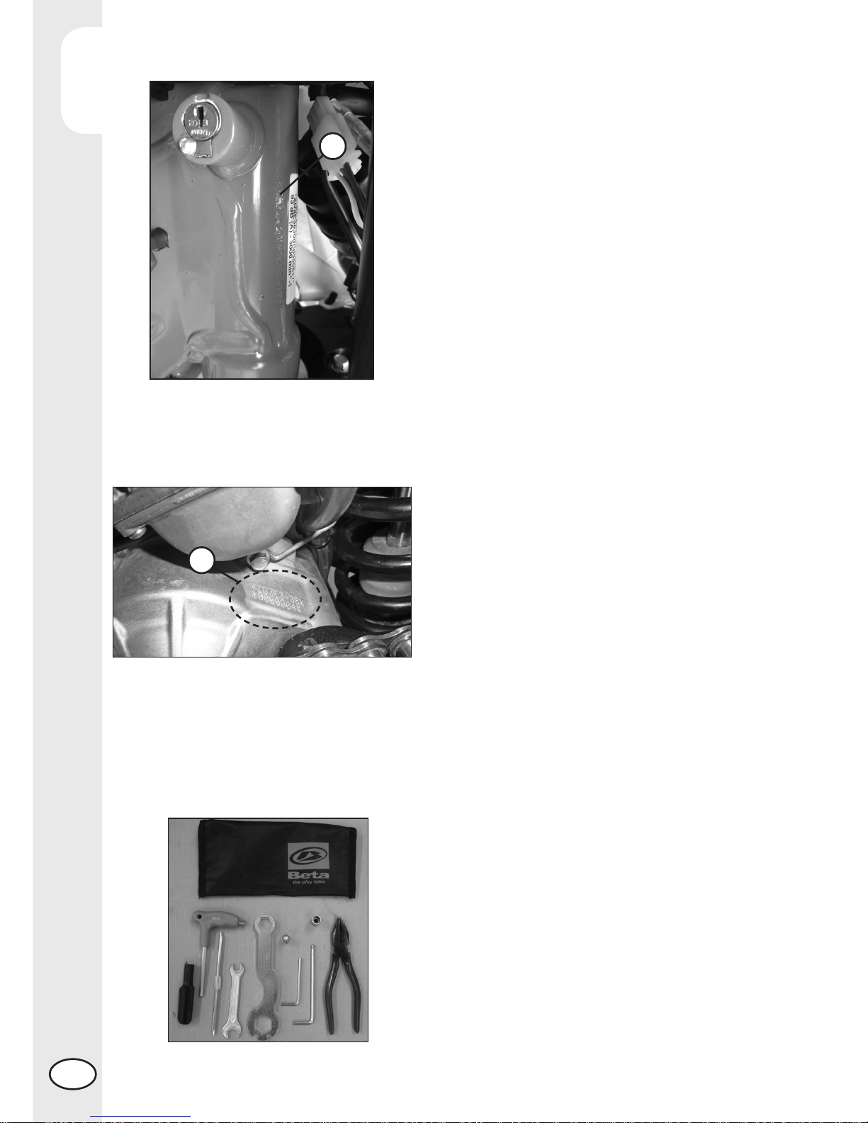
Vehicle identification data ........................................................................ 8
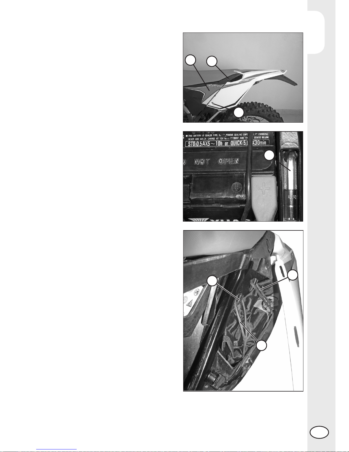
Delivery................................................................................................ 8
Load .................................................................................................. 10
Tyres .................................................................................................. 10
Steering lock ....................................................................................... 11
Familiarizing with your vehicle ................................................................ 12
Controls.............................................................................................. 13
Specifications ...................................................................................... 21
Wiring diagrams RR 2t ......................................................................... 25
Electrical devices.................................................................................. 27
Devices for Euro 3 version...................................................................... 28
CHAPTER 2 OPERATION ................................................................. 29
Checks to be performed before each ride ................................................. 30
Lubricants............................................................................................ 31
Running-in ........................................................................................... 31
Starting the engine................................................................................ 32
Refuelling............................................................................................ 33
CHAPTER 3 CHECKS AND MAINTENANCE..................................... 35
Changing the gear and clutch oil ............................................................ 36
Check the level of the front and rear brake fluid and bleeding....................... 37
Check the front and rear brake pads........................................................ 39
Check the oil level in the hydraulic clutch and bleeding ............................... 40
Fork oil............................................................................................... 41
Air filter .............................................................................................. 44
Spark plug .......................................................................................... 45
Carburetor .......................................................................................... 47
Coolant.............................................................................................. 48
Drive chain maintenance and wear.......................................................... 49
Charging the battery............................................................................. 50
Cleaning and checking the vehicle .......................................................... 51
Scheduled maintenance......................................................................... 52
Prolonged inactivity............................................................................... 54
CHAPTER 4 ADJUSTMENTS............................................................. 56
Brake adjustment: front lever and brake pedal............................................ 57
Adjusting the home position of the clutch lever............................................ 57

CONTENTS
4
GB
Adjusting the handlebars........................................................................ 57
Gas control adjustment .......................................................................... 58
Checking and adjusting the steering play.................................................. 58
Adjusting the Suspensions: telescopic fork and shock absorber.............. 59 ÷ 61
Tensioning the chain.............................................................................. 61
Idling setting........................................................................................ 62
Exhaust valve control adjustment.............................................................. 63
CHAPTER 5 REPLACEMENTS ........................................................... 64
Replacing the brake pads: front and rear .................................................. 65
Replacing the headlight bulbs ................................................................. 67
Replacing the rear optical batch ............................................................. 67
CHAPTER 6 TROUBLESHOOTING.................................................... 70
INDEX.............................................................................................. 72

5GB
OPERATING INSTRUCTIONS
•The vehicle must be accompanied by: number-plate, registration document, tax
disc and insurance.
•Do not carry animals, pets or loose objects that can stick out from the vehicle.
•Riding without a crash helmet is forbidden.
•Always ride with the low beam on.
•Any modifications of the engine or other parts resulting in a power and/or speed
increase are punishable by severe sanctions including the confiscation of the vehicle.
•To protect your safety and that of others, always drive carefully and with your helmet
on.
WARNING
Any modifications and tampering with the vehicle during the warranty period exempt
the manufacturer from all responsibility and invalidate warranty.
ECOLOGIC GUIDE
•Every vehicle powered by an internal combustion engine produces an amount of
noise (noise pollution) and gases (air pollution) which varies with the riding style.
•The abatement of noise and air pollution levels is the duty of everybody. Avoid
full-throttle starts, sudden acceleration and abrupt braking. This will reduce noise
emission as well as the wear and tear of the tyres and mechanical parts, and will
also allow a considerable reduction in fuel consumption.

6
GB
RIDING SAFETY
•Observe the Highway Code.
•Always put on and fasten a homologated helmet.
•Always ride with the low beam on.
•Always keep the crash helmet visor clean.
•Avoid wearing garments with hanging ends.
•Do not keep sharp or brittle objects in your pockets while riding.
•Properly adjust the rearview mirrors.
•Always ride in a seated position, with both hands on the handlebars and both feet
on the footrests.
•Always pay attention and do not allow anything to distract you while riding.
•Do not eat, drink, smoke, use a mobile phone, etc. while riding.
•Do not wear headphones to listen to music while riding.
•Never ride abreast with other vehicles.
•Do not tow and avoid being towed by other vehicles.
•Always keep a safe distance from other vehicles.
•Do not sit on the vehicle when it is on its stand.
•Do not start off while the vehicle is on its stand.
•Do not pull out the stand when the vehicle is facing downhill.
•Avoid swaying and wheelies as they are extremely dangerous for your own and
other people’s safety as well as for your vehicle.
•Always apply both brakes on dry roads with no gravel and sand. Using one brake
may be dangerous and cause uncontrolled skidding.
•To reduce the braking distance, always apply both brakes.
•On wet roads and in off-road riding, drive with care and at moderate speed. Take
special care in applying the brakes.
•Do not start the engine in closed places.

1
GENERAL INFORMATION
7GB
CONTENTS
CHAPTER 1 GENERAL INFORMATION
Vehicle identification data
Delivery
Load
Tyres
Steering lock
Familiarizing with your vehicle
Controls
Specifications
Wiring diagram
Electrical devices
Euro 3 devices

1
GENERAL INFORMATION
8
GB
VEHICLE IDENTIFICATION DATA
FRAME IDENTIFICATION
Frame identification data Aare stamped
on the right side of the steering head tube.
ENGINE IDENTIFICATION
Engine identification data Bare stamped
in the area shown in the figure.
WARNING:
Tampering with the identification numbers
is severely punished by law.
DELIVERY
•The vehicle is supplied ready for use.
However, it is advisable to conduct a few
simple checks before riding:
- Check the tyre pressures.
- Check the oil level in the engine.
•The following items are supplied as
standard: operation and maintenance
manual, tool kit (see photo).
A
B

1
GENERAL INFORMATION
9GB
Get off the male end wrenches and hexa-
gon socket 3.
With these is possible to unscrew the
screw 4.
Pull the left cover of rear fender and unhook
two rubber bande 5. Now the toolkit 6
is accessibile.
To take the tool kit, push the button 1to
get off the saddle. Pull back the saddle.
Pull the rear side panel 2to disassemble it.
1
2
3
4
6
5
5

1
GENERAL INFORMATION
10
GB
LOAD
•To avoid to let the vehicle be unstable, do not carry bulky or heavy objects.
•Do not carry objects that stick from the vehicle or cover the lighting and signalling
devices.
TYRES
•Only fit tyres approved by BETAMOTOR.
Unsuitable tyres can adversely affect the
road holding of the vehicle.
•To protect your safety, immediately re-
place any damaged tyres.
•Slick tyres adversely affect the road
holding of the vehicle, especially on wet
roads and in off-road riding.
•Insufficient pressure results in abnormal
wear and overheating of the tyres.
•The front and rear tyres must have the
same tread design.
pressure is too high
TYRES PRESSION ENDURO
RR 250 - 300
TYRE
Off-road
Road
rear
1,0 bar
1,8 bar
front
1,0 bar
1,5 bar
pressure is too low
pressure is correct

1
GENERAL INFORMATION
11 GB
Note
The type, condition and pressure of the tyres affect the road holding of the vehicle.
For this reason it is essential to check them before each journey.
•The size of the tyres is shown in the technical specifications and in the vehicle
handbook.
•Check the condition of the tyres before each journey. Inspect the tyres for cuts and
for nails or other pointed objects sticking out of them. Regarding the minimum al-
lowable thickness of the tread, observe the regulations in force in your country. We
recommend replacing the tyres at the latest when the tread is 2 mm thick.
•Check the inflating pressure on a regular basis while the tyres are cold. Proper
pressure ensures optimum riding comfort and prolongs the life of the tyres.
STEERING LOCK
The vehicle is supplied with one key and
a spare to be used for the steering lock.
WARNING:
Do not keep the spare keys in the vehicle.
Keep the keys in a safe and easy-to-reach
place. The code number stamped on the
keys should be copied on this manual (or
elsewhere) so it can be used to ask for
duplicates should both keys be lost.
To engage the steering lock, fully turn the
handlebars to the left, insert the key, press
and turn it fully anticlockwise and then
release it.

1
GENERAL INFORMATION
12
GB
FAMILIARIZING WITH THE VEHICLE
Main parts:
1 - Fuel tank
2 - Tank cap
3 - Silencer
4 - Rear shock absorber
5 - Headlight
6 - Rear light
7 - Side stand
8 - Fork
9 - Rider’s footrests
10 - Lower bumper
(Bumper kit)
11 - Saddle
12 - Engine
13 - Front mudguard
14 - Number-plate holder
15 - Kick-start
16 - Front side panel
17 - Rear side panel
18 - Fork covers
19 - Rear mudguard
20 - Cover air filter
5
8
21
11
19 14
12
94
6
3
17
10
13
16 18
20
7
9
15

1
GENERAL INFORMATION
13 GB
CONTROLS
CLUTCH LEVER
Clutch lever 1is fitted to the left-hand side
of the handlebars. Screw Acan be used
to alter the home position of the lever (see
Adjustments).
FRONT BRAKE LEVER
Front brake lever 2is fitted to the right-hand
side of the handlebars. Screw Bcan be
used to adjust the home position of the
lever (see Adjustments).
GEARCHANGE LEVER
Gearchange lever 3is fitted to the left side
of the engine.
The positions corresponding to the different
gears are shown in the figure.
The neutral position is between the 1st and
2nd gears.
BRAKE PEDAL
Brake pedal 4is located in front of the
right-hand footrest.
The position of the pedal can be adjusted
to suit the requirements of the driver (see
Adjustments).
A
1
1
2
3456
3
4
2
B

1
GENERAL INFORMATION
14
GB
LH SWITCH
Dip switch 2has three positions:
A= lights off
B= low beam on
C= high beam on
Button 3operates the horn.
Switch 4is used to stop the engine. Press
the button until the engine stops.
INDICATOR SWITCH
Shifting lever 5left or right activates the
left or right indicators (if installed). When
released, the lever returns to the central
position. Press it to turn the indicators off.
KICKSTART
Kickstart 6is fitted to the right-hand side
of the engine.
The upper part of the kickstart can be
oriented.
SIDE STAND
Press down side stand 7with the foot and
lean the vehicle against it.
Ensure that the ground is solid and the
vehicle stands steadily.
If the vehicle is used off-road, the closed
stand can be further fastened by means of
rubber band 8.
STARTER BUTTON
Starte button 1 is located on the right-hand
side of the handlebars and operate the
electri engine starter. Push the button until
the engine sterts.
Do not press the button 1 while the engine
is running.
1
4
2
53
C
B
A
6
8
7

1
GENERAL INFORMATION
15 GB
DIGITAL RPM INDICATOR
GENERAL SPECIFICATIONS
SPEED/DISTANCE SENSOR: Non-contact magnetic
SCREEN MEASUREMENTS: 125mm x 41mm x 34mm
STORAGE TEMPERATURE: -20°C to 80°C (-4°F to 176°F)
BATTERY: 3V CR2032
BATTERY LIFE: Approximately one year
EXTERNAL CURRENT SUPPLY: 12V DC
GENERAL INFORMATION
Backlight:
The digital speedometer/odometer is backlit to enable reading where there is poor
or no lighting.
Using the 12V external current supply (instrument connected to vehicle battery):
• Backlighting is permanent with 12V current supply.
• After 20s of inactivity the backlighting will switch off. To switch it back on press any
button or turn the wheel.
Using only the internal battery:
• Backlighting will stay on for 4 seconds before switching off.
• With the LO symbol, the backlighting will not switch on. The symbol appears
when the battery voltage is lower than 2.45V.
Reset Button:
Using the Reset button, located on the back of the instrument, all travel data will be
deleted, including date and time.
Internal battery:
The instrument houses a 3.0V internal button cell battery (CR2032). The instrument can
only work with this battery. The symbol appears when the battery is running
low. To change the battery, unscrew the cap located on the back of the instrument
using a coin.
Once the battery has been changed, make sure that the positive side is facing
outwards.
REPLACE THE BATTERY WITH ANOTHER CR2032-TYPE BATTERY.

1
GENERAL INFORMATION
16
GB
SETTING THE PARAMETERS
General information:
Allowed settings:
• Km/h (kilometres per hour) or M/h (Miles per hour)
• Wheel size (rolling circumference) [mm]
• Clock format: 12-hour / 24-hour
• Current date
• Maintenance
TO ENTER THE PARAMETER SETTINGS MODE HOLD DOWN THE RIGHT AND LEFT
BUTTONS FOR APPROX. 3s.
THE WORD “Unit” WILL FLASH ON THE DISPLAY.
The operational logic is structured as follows:
•The instrument enters SETUP mode displaying the parameters according to the
sequence listed above.
•The instrument displays the parameter to be changed for a few seconds in flash
mode.
•If you wish to change the parameter displayed for those few seconds simply
edit the values by pressing the right and/or left buttons (according to the modes
listed below), otherwise wait a few seconds (approx. 5 s) to proceed to the next
parameter.
•When the parameter has been edited to the desired value, the instrument au-
tomatically moves onto the next setting, there is no need to press any button of
confirmation.
•If you only wish to enter the setup mode to view the configured settings, simply wait
without pressing any buttons; the instrument will display all of the set parameters
and will then automatically go back to “Normal Mode”.
SETUP SEQUENCE
Select unit of measure
Wheel size
Clock format
Current date
Maintenance

1
GENERAL INFORMATION
17 GB
Selecting the unit of measure (Km/h or M/h):
TO SELECT THE UNIT OF MEASURE (Km/h or M/h), PRESS THE RIGHT OR LEFT
BUTTON.
WAIT 5 SECONDS TO PROCEED TO THE NEXT SETTING.
DO NOT PRESS ANY BUTTONS.
Selecting the wheel size (rolling circumference):
The instrument has programmed two rolling circumference measurements for the front
wheel: 2190mm (Enduro version - 21” rim) or 1890mm (Motard version – 17” rim).
PRESS THE LEFT BUTTON TO SELECT ONE OF THE TWO OPTIONS.
WAIT 5 SECONDS TO PROCEED TO THE NEXT SETTING. DO NOT PRESS ANY
BUTTONS.
Selecting the clock format (12- or 24-hour):
The default setting on the instrument is the 12-hour clock.
TO SELECT THE 12- OR 24-HOUR CLOCK, PRESS THE RIGHT OR LEFT BUTTON.
WAIT 5 SECONDS TO PROCEED TO THE NEXT SETTING. DO NOT PRESS ANY
BUTTONS.
Setting the Time:
The time is set by increasing or decreasing it by 1 minute steps.
PRESS THE LEFT BUTTON TO DECREASE THE TIME.
PRESS THE RIGHT BUTTON TO INCREASE IT.
WAIT 5 SECONDS TO PROCEED TO THE NEXT SETTING. DO NOT PRESS ANY
BUTTONS.
Selecting the maintenance memo
The instrument displays the countdown to maintenance operations based on the data
entered by the user. The data is based on the kilometres and miles travelled accord-
ing to
the unit of measure selected by the user. The factory setting is on “OFF”.
PRESS THE LEFT BUTTON TO LOWER THE NUMBER. PRESS THE RIGHT BUTTON
TO RAISE IT (max value 10000).
WAIT 5 SECONDS TO EXIT SETUP MODE.
DO NOT PRESS ANY BUTTONS.

1
GENERAL INFORMATION
18
GB
SCREENS
Switching between 3 normal modes
All of the information that the instrument is capable of providing is displayed on one of
these 3 screens.
The instrument will stay on the set screen until a button is pressed to switch to another
screen.
TO SWITCH FROM ONE SCREEN TO ANOTHER, PRESS EITHER THE RIGHT OR
LEFT BUTTON BRIEFLY.
Screen 1:
• Speed • Distance 1 (DST) • Time
Screen 2:
• Speed • Distance 2 (DST2 ) • Time
Screen 3:
• Maximum speed (MAX) • Average speed (AVG)
• Accumulated running time (ART) • Odometer (ODO)
* Note: The maximum and average speeds are updated automatically when the
user accesses screen 3.
FEATURES
General information:
During normal use the instrument is in “Normal” mode.
Available modes:
• Sleep Mode
• Choose from 3 “Normal” screens
• Clear Distance 1 (DST1)
• Clear Distance 2 (DST2)
• Clear Maximum/Average Speed (MAX/AVG)
Sleep Mode:
If the instrument does not receive any input for 5 minutes (either from the movement
of the wheel or a button), it will go into “Sleep Mode”. In “Sleep Mode” only the
time appears on the screen.
To exit “Sleep Mode” all the instrument requires is an input, either from the movement of
the sensor or by pressing a button.

1
GENERAL INFORMATION
19 GB
SPEEDOMETER
Speed
The speed is displayed in the centre of screens 1 or 2 and can range from 0 to 399.9
km/h or M/h. The unit of measure (km/h or M/h) appears next to the speed reading.
Maximum (Max) and Average (AVG) speed
The Maximum (MAX) or Average (AVG) speeds are displayed on screen 3 to the left
of the display. The instrument automatically updates both the maximum (MAX) and
average (AVG) speeds. To clear the maximum (MAX) and average (AVG) speeds,
hold the right button down for 5 seconds.
Note: you must be on screen 3 to clear the speeds.
ADJUSTING THE TRAVELLED DISTANCE METER
Description
The travelled distance meter displays the distance that has been travelled since it
was last cleared. It has two different distinguishing distances.
Table of contents
Other Beta Motorcycle manuals

Beta
Beta EVO 2T 2010 User manual

Beta
Beta RR 125 series User manual

Beta
Beta MINITRIAL 50 User manual

Beta
Beta EVO 4T User manual

Beta
Beta RE 125 User manual

Beta
Beta RR 350 User manual

Beta
Beta Rev 4T User manual

Beta
Beta RR 400 User manual

Beta
Beta 350-498 RR User guide

Beta
Beta RR 250 2T EUROPA 2019 User manual