Beta RR 50 CC series User manual

1GB
RR 50 CC ENDURO / ENDURO STD / MOTARD /
MOTARD STD / FACTORY / TRACK
Thanks for you preference, and have a good time! This hand-
book contains the information you need to properly operate and
maintain your motorcycle.
The data and specifications provided in this manual does not constitute an
engagement on the part of BETAMOTOR S.p.A. BETAMOTOR reserves the
right to make any changes and improvements to its models at any moment
and without notice.

2
GB
IMPORTANT
We recommend you to check all the tightenings after the first one
or two hours’ ride over rough ground. Special attention should
be paid to the following parts:
•rear sprocket
•ensure that the footrests are properly fixed
•front/rear brake levers/calipers/discs
•check that the plastics are properly fastened
•engine bolts
•shock absorber bolts/swingarm
•wheel hubs/spokes
•rear frame
•pipe connections
•tensioning the chain
IMPORTANT
For any servicing requirements, please get in contact with Beta-
motor’s authorized service network.

INDICE
3GB
Operating instructions.............................................................................. 5
Ecologic guide....................................................................................... 5
Riding safety.......................................................................................... 6
CHAPTER 1 GENERAL INFORMATION.............................................. 7
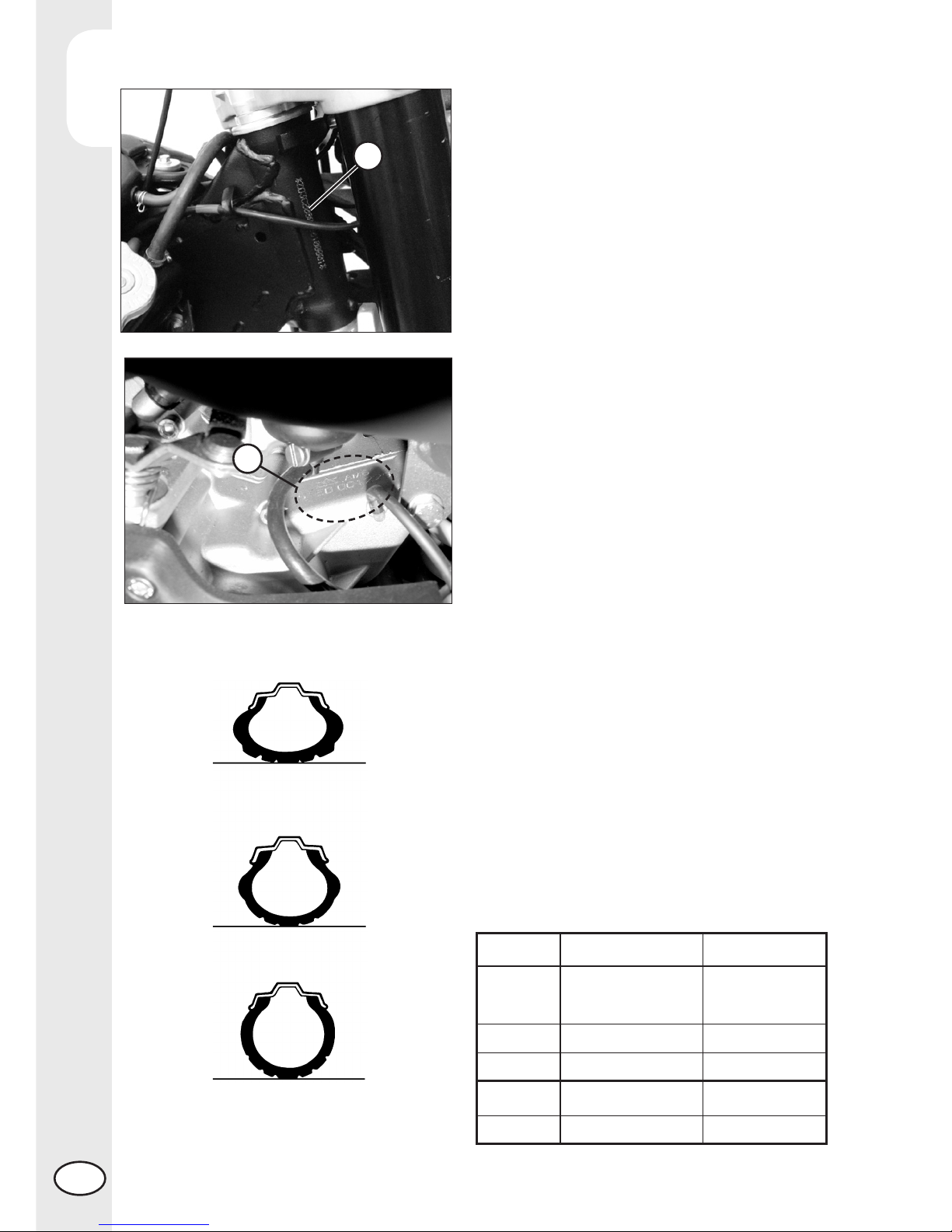
Vehicle identification data ........................................................................ 8
Tyres .................................................................................................... 8
Familiarizing with your vehicle ................................................................ 10
Controls.............................................................................................. 11
Digital RPM indicator operating instructions ............................................... 13
Keys .................................................................................................. 19
Steering lock ....................................................................................... 19
Specifications ...................................................................................... 20
Wiring diagrams RR 50 ........................................................................ 24
Recommended lubricants and liquids........................................................ 26
CHAPTER 2 OPERATION ................................................................. 27
Checks and maintenance before and after use........................................... 28
Running-in ........................................................................................... 28
Refuelling............................................................................................ 29
Starting the engine................................................................................ 30
CHAPTER 3 CHECKS AND MAINTENANCE..................................... 31
Gearbox oil ........................................................................................ 32
Brake pump oil .................................................................................... 33
Air filter .............................................................................................. 34
Spark plug .......................................................................................... 35
Front brake.......................................................................................... 36
Rear brake .......................................................................................... 36
Coolant.............................................................................................. 37
Operations after cleaning ...................................................................... 37
Scheduled maintenance......................................................................... 38
CHAPTER 4 ADJUSTMENTS............................................................. 39
Brake adjustment ................................................................................. 40
Clutch lever adjustment.......................................................................... 40
Idling setting........................................................................................ 41
Adjustment of gas clearance................................................................... 41
Checking and adjusting the steering play.................................................. 41
Tensioning the chain.............................................................................. 42
Adjusting the shock absorber .................................................................. 43

INDICE
4
GB
CHAPTER 6 TROUBLESHOOTING.................................................... 45
Troubleshooting.................................................................................... 46
INDEX.............................................................................................. 47

5GB
OPERATING INSTRUCTIONS
•The vehicle must be accompanied by: number-plate, registration document, tax
disc and insurance.
•Do not carry animals, pets or loose objects that can stick out from the vehicle.
•Riding without a crash helmet is forbidden.
•Always ride with the low beam on.
•Any modifications of the engine or other parts resulting in a power and/or speed
increase are punishable by severe sanctions including the confiscation of the vehicle.
•To protect your safety and that of others, always drive carefully and with your helmet
on.
WARNING
Any modifications and tampering with the vehicle during the warranty period exempt
the manufacturer from all responsibility and invalidate warranty.
ECOLOGIC GUIDE
•Every vehicle powered by an internal combustion engine produces an amount of
noise (noise pollution) and gases (air pollution) which varies with the riding style.
•The abatement of noise and air pollution levels is the duty of everybody. Avoid
full-throttle starts, sudden acceleration and abrupt braking. This will reduce noise
emission as well as the wear and tear of the tyres and mechanical parts, and will
also allow a considerable reduction in fuel consumption.

6
GB
RIDING SAFETY
•Observe the Highway Code.
•Always put on and fasten a homologated helmet.
•Always ride with the low beam on.
•Always keep the crash helmet visor clean.
•Avoid wearing garments with hanging ends.
•Do not keep sharp or brittle objects in your pockets while riding.
•Properly adjust the rearview mirrors.
•Always ride in a seated position, with both hands on the handlebars and both feet
on the footrests.
•Always pay attention and do not allow anything to distract you while riding.
•Do not eat, drink, smoke, use a mobile phone, etc. while riding.
•Do not wear headphones to listen to music while riding.
•Never ride abreast with other vehicles.
•Do not tow and avoid being towed by other vehicles.
•Always keep a safe distance from other vehicles.
•Do not sit on the vehicle when it is on its stand.
•Do not start off while the vehicle is on its stand.
•Do not pull out the stand when the vehicle is facing downhill.
•Avoid swaying and wheelies as they are extremely dangerous for your own and
other people’s safety as well as for your vehicle.
•Always apply both brakes on dry roads with no gravel and sand. Using one brake
may be dangerous and cause uncontrolled skidding.
•To reduce the braking distance, always apply both brakes.
•On wet roads and in off-road riding, drive with care and at moderate speed. Take
special care in applying the brakes.
•Do not start the engine in closed places.

1
GENERAL INFORMATION
7GB
CONTENTS
CHAPTER 1 GENERAL INFORMATION
Vehicle identification data
Tyres
Familiarizing with your vehicle
Controls
Digital RPM indicator operating instructions
Specifications
Wiring diagram
Recommended lubricants and liquids

1
GENERAL INFORMATION
8
GB
VEHICLE IDENTIFICATION DATA
FRAME IDENTIFICATION
Frame identification data Aare stamped
on the right side of the steering head tube.
ENGINE IDENTIFICATION
Engine identification data Bare stamped
on the l.h. side half crankcase.
WARNING:
Tampering with the identification numbers
is severely punished by law.
B
A
TYRES
WARNING:
For your riding safety, frequently check
the tyres.
•Keep the tyre pressures within the pre-
scribed range.
•Check the tyre pressures every other
week.
•Always measure the inflating pressures
when the tyres are cold.
Enduro front rear
Size 80/90-21 48P or 110/80-18 58P
90/90-21 54R (Factory) 120/90-18 (Factory)
Bar 1 1
Motard front rear
Size 100/80-17 57H 130/70-17 62H
Bar 1,9 2
pressure is too high
pressure is too low
pressure is correct

1
GENERAL INFORMATION
9GB
Note
The type, condition and pressure of the tyres affect the road holding of the vehicle.
For this reason it is essential to check them before each journey.
•The size of the tyres is shown in the technical specifications and in the vehicle
handbook.
•Check the condition of the tyres before each journey. Inspect the tyres for cuts and
for nails or other pointed objects sticking out of them. Regarding the minimum al-
lowable thickness of the tread, observe the regulations in force in your country. We
recommend replacing the tyres at the latest when the tread is 2 mm thick.
•Check the inflating pressure on a regular basis while the tyres are cold. Proper
pressure ensures optimum riding comfort and prolongs the life of the tyres.

1
GENERAL INFORMATION
10
GB
FAMILIARIZING WITH THE VEHICLE
Main parts:
1 Tank cap
2 Air filter
3 Side stand
4 Fuel cock
5 Fuel tank
6 Radiator cap
7 Kick-starter
1
2
3
8
10
4
56
7
9
8 Muffler
9 Silencer
10 Mixer oil tank cap
(not fitted on Factory version)

1
GENERAL INFORMATION
11 GB
CONTROLS
CLUTCH LEVER
The clutch lever 1is located on the left
side of the handlebar. See the Adjustments
chapter to adjust.
STARTER
The starter lever 2is located on the left side
of the handlebar. Turn the lever counter-
clockwise to operate.
SWITCH
The dip and service switch is located on
the left side of the handlebar and is com-
posed as follows:
3Horn button;
4Dip switch
( high beam ; low beam)
5Shut-down;
6Turn signal light switch
FRONT BRAKE LEVER AND GAS CONTROL
The front brake lever 7and the gas throt-
tle 8are located on the right side of the
handlebar.
7
8
1
52
364

1
GENERAL INFORMATION
12
GB
1
2
3
456
A
GEARCHANGE LEVER
Gearchange lever Ais fitted to the left side
of the engine.
The positions corresponding to the different
gears are shown in the figure.
BRAKE PEDAL
Brake pedal 9is located in front of the
right-hand footrest.
9
KICKSTART
The kick-starter pedal 10 is located on the
right side of the engine. The upper part is
rotatable. To start, depress the kick-starter
outward and with a quick movement down-
ward. The pedal will automatically return
upwards. After starting, manually fold the
pedal in the rest position.
10

1
GENERAL INFORMATION
13 GB
1 GENERAL SPECIFICATIONS AND GENERAL INFORMATIONS
1.1 GENERAL SPECIFICATIONS
SPEED/DISTANCE SENSOR: Non-contact magnetic
DISPLAY MEASUREMENTS: 125mm x 41mm x 34mm
STORAGE TEMPERATURE: -20°C to 80°C (-4°F to 176°F)
BATTERY: 3V CR2032
BATTERY LIFE: Approximately one year
EXTERNAL CURRENT SUPPLY: 12V DC
1.2 GENERAL INFORMATIONS
Backlight:
The digital speedometer/odometer is backlit to enable reading where there is poor
or no lighting.
When using supplied power with the engine on:
•Theback-lightingisonpermanentlywhentheengineisrunning.
1
2
3
6
5
4
7
1 LCD
2 High beam light
3 Idle pilot light
4 Oil tank level light
5 Indicator light
6 Push-button 1
7 Push-button 2
DIGITAL RPM INDICATOR OPERATING INSTRUCTIONS
Series RR 50 Enduro - Enduro standard - Factory - Motard - Motard standard - Track
CONTENTS
1 GENERAL SPECIFICATIONS AND GENERAL INFORMATIONS
1.1 General specifications
1.2 General informations
2 SETTING THE PARAMETERS
2.1 Setup sequence
2.1.1 Selecting the unit of measure
2.1.2 Selecting the wheel size
2.1.3 Selecting the clock format
2.1.4 Setting the Time
2.1.5 Selecting the maintenance memo
3 SCREENS
4 FEATURES
5 SPEEDOMETER
6 ADJUSTING THE TRAVELLED DISTANCE METER
7 WARNING LIGHTS

1
GENERAL INFORMATION
14
GB
Using only the internal battery:
•WiththeLOsymbol,thebacklightingwillnotswitchon.Thesymbolappears
when the battery voltage is lower than 2.45V.
Reset Button:
Using the Reset button, located on the back of the instrument, all travel data will be
deleted, including date and time.
Internal battery:
The instrument houses a 3.0V internal button cell battery (CR2032). The instrument can
only work with this battery. The symbol appears when the battery is running
low. To change the battery, unscrew the cap located on the back of the instrument
using a coin.
Once the battery has been changed, make sure that the positive side is facing
outwards.
REPLACE THE BATTERY WITH ANOTHER CR2032-TYPE BATTERY.
2 SETTING THE PARAMETERS
General information:
Allowed settings:
•Km/h(kilometresperhour)orM/h(Milesperhour)
•Wheelsize(rollingcircumference)[mm]
•Clockformat:12-hour/24-hour
•Currentdate
•Maintenance
TO ENTER THE PARAMETER SETTINGS MODE HOLD DOWN THE RIGHT AND LEFT
BUTTONS FOR APPROX. 3s.
THE WORD “Unit” WILL FLASH ON THE DISPLAY.
The operational logic is structured as follows:
•The instrument enters SETUP mode displaying the parameters according to the
sequence listed above.
•The instrument displays the parameter to be changed for a few seconds in flash
mode.
•If you wish to change the parameter displayed for those few seconds simply
edit the values by pressing the right and/or left buttons (according to the modes
listed below), otherwise wait a few seconds (approx. 5 s) to proceed to the next
parameter.
•When the parameter has been edited to the desired value, the instrument au-
tomatically moves onto the next setting, there is no need to press any button of
confirmation.
•If you only wish to enter the setup mode to view the configured settings, simply wait
without pressing any buttons; the instrument will display all of the set parameters
and will then automatically go back to “Normal Mode”.

1
GENERAL INFORMATION
15 GB
2.1 SETUP SEQUENCE
Select unit of measure
Wheel size
Clock format
Setting the Time
Maintenance reminder
2.1.1 Selecting the unit of measure (Km/h or M/h):
TO SELECT THE UNIT OF MEASURE (Km/h or M/h), PRESS THE RIGHT OR LEFT
BUTTON.
WAIT 5 SECONDS TO PROCEED TO THE NEXT SETTING.
DO NOT PRESS ANY BUTTONS.
2.1.2 Selecting the wheel size (rolling circumference):
The instrument has programmed two rolling circumference measurements for the front
wheel: larger size (Enduro version - 21” rim) or smaller size (Motard version – 17” rim).
PRESS THE LEFT BUTTON TO SELECT ONE OF THE TWO OPTIONS.
WAIT 5 SECONDS TO PROCEED TO THE NEXT SETTING. DO NOT PRESS ANY
BUTTONS.
2.1.3 Selecting the clock format (12- or 24-hour):
The default setting on the instrument is the 12-hour clock.
TO SELECT THE 12- OR 24-HOUR CLOCK, PRESS THE RIGHT OR LEFT BUTTON.
WAIT 5 SECONDS TO PROCEED TO THE NEXT SETTING. DO NOT PRESS ANY
BUTTONS.
2.1.4 Setting the Time:
The time is set by increasing or decreasing it by 1 minute steps.
PRESS THE LEFT BUTTON TO DECREASE THE TIME.
PRESS THE RIGHT BUTTON TO INCREASE IT.
WAIT 5 SECONDS TO PROCEED TO THE NEXT SETTING. DO NOT PRESS ANY
BUTTONS.
2.1.5 Selecting the maintenance reminder
The instrument displays the countdown to maintenance operations based on the data
entered by the user. The data is based on the kilometres and miles travelled according
to the unit of measure selected by the user. The factory setting is on “OFF”.
PRESS THE LEFT BUTTON TO LOWER THE NUMBER. PRESS THE RIGHT BUTTON
TO RAISE IT (max value 10000Km).
WAIT 5 SECONDS TO EXIT SETUP MODE.
DO NOT PRESS ANY BUTTONS.

1
GENERAL INFORMATION
16
GB
3 SCREENS
Switching between 3 normal modes
All of the information that the instrument is capable of providing is displayed on one of
these 3 screens.
The instrument will stay on the set screen until a button is pressed to switch to another
screen.
TO SWITCH FROM ONE SCREEN TO ANOTHER, PRESS EITHER THE RIGHT OR
LEFT BUTTON BRIEFLY.
Screen 1:
•Speed•Distance1(DST)•Time
Screen 2:
•Speed•Distance2(DST2)•Time
Screen 3:
•Maximumspeed(MAX)•Averagespeed(AVG)
•Accumulatedrunningtime(ART)•Odometer(ODO)
* Note: The maximum and average speeds are updated automatically when the
user accesses screen 3.
4 FEATURES
General information:
During normal use the instrument is in “Normal” mode.
Available modes:
•SleepMode
•Choosefrom3“Normal”screens
•ClearDistance1(DST1)
•ClearDistance2(DST2)
•ClearMaximum/AverageSpeed(MAX/AVG)
Sleep Mode:
If the instrument does not receive any input for 5 minutes (either from the movement
of the wheel or a button), it will go into “Sleep Mode”. In “Sleep Mode” only the
time appears on the screen.
To exit “Sleep Mode” all the instrument requires is an input, either from the movement of
the sensor or by pressing a button.

1
GENERAL INFORMATION
17 GB
5 SPEEDOMETER
Speed
The speed is displayed in the centre of screens 1 or 2 and can range from 0 to 399.9
km/h or M/h. The unit of measure (km/h or M/h) appears next to the speed reading.
Maximum (Max) and Average (AVG) speed
The Maximum (MAX) or Average (AVG) speeds are displayed on screen 3 to the left
of the display. The instrument automatically updates both the maximum (MAX) and
average (AVG) speeds. To clear the maximum (MAX) and average (AVG) speeds,
hold the right button down for 5 seconds.
Note: you must be on screen 3 to clear the speeds.
6 ADJUSTING THE TRAVELLED DISTANCE METER
Description
The travelled distance meter displays the distance that has been travelled since it
was last cleared. It has two different distinguishing distances.

1
GENERAL INFORMATION
18
GB
Travelled distance (DST)
The travelled distance can range from 0 to 9999.9 miles or kilometers and appears
on the right side of screen 1. To clear the travelled distance, hold the right button
down for 5 seconds.
Note: you must be on screen 1 to clear the travelled distance.
Travelled distance 2 (DST 2)
Travelled distance 2 can range from 0 to 9999.9 miles or kilometers and appears
on the right side of screen 2. To clear the travelled distance, hold the right button
down for 5 seconds.
Note: you must be on screen 2 to clear the travelled distance.
7 WARNING LIGHTS
7.1 Headlight indicator
The system activates the indicator in synchrony with the activation of the mains beams.
7.2 Direction indicator lights
The system activates the indicator in synchrony with the activation of the direction
indicators.
7.3 Neutral indicator light
Indicates the position of the gear lever in neutral.
7.4 Mixer oil indicator light
Indicates a low level of mixer oil.
If the warning light comes on, IMMEDIATELY STOP THE MOTORBIKE AND TURN
OFF THE ENGINE. Refuel with special oil as indicated in the “Table of Lubricants
and Recommended Liquids” on page 26.

1
GENERAL INFORMATION
19 GB
KEYS
The vehicle is supplied with two keys (one
key and its spare), each of which can
be used for the steering lock switch, for
switching the engine on and off and the
refuelling door.
- Turn the key to to start up the engine.
- Turn the key to to switch off the en-
gine.
STEERING LOCK
AThe steering lock is off.
BThe steering lock is on.
To activate the steering lock:
- turn the handlebar counter-clockwise;
- push the key and turn counter-clockwise;
Remove the key from this position. The
engine cannot be started.
To deactivate the steering lock:
- turn the key clockwise;
- turn the handlebar clockwise;
From this position, the handlebar is free to
move, the key can be removed and the
engine cannot be started.
WARNING: do not keep the spare key
inside the vehicle, but in a safe place.
We suggest you note the code number
stamped on the keys. In this way you can
obtain a duplicate.
B
A

1
GENERAL INFORMATION
20
GB
TECHNICAL DATA
dry weight (all models) ...................................................................... 85 kg
Dimensions (ENDURO)
total length ...............................................................................2.085 mm
total width...................................................................................815 mm
total height...............................................................................1.225 mm
wheelbase ...............................................................................1.415 mm
saddle height...............................................................................935 mm
clearance from ground ..................................................................350 mm
footrest height ..............................................................................405 mm
Dimensions (MOTARD and TRACK)
total length ...............................................................................2.000 mm
total width...................................................................................805 mm
total height...............................................................................1.155 mm
wheelbase ...............................................................................1.390 mm
saddle height...............................................................................900 mm
clearance from ground ..................................................................315 mm
footrest height ..............................................................................365 mm
Dimensions (FACTORY)
total length ...............................................................................2.085 mm
total width...................................................................................815 mm
total height...............................................................................1.225 mm
wheelbase ...............................................................................1.415 mm
saddle height...............................................................................935 mm
clearance from ground ..................................................................350 mm
footrest height ..............................................................................405 mm
Dimensions (STD)
total length ...............................................................................2.052 mm
total width...................................................................................805 mm
total height...............................................................................1.190 mm
wheelbase ...............................................................................1.385 mm
saddle height................................................................................930 mm
clearance from ground ...................................................................345 mm
footrest height ...............................................................................395 mm
Dimensions (MOTARD STD)
total length ................................................................................2.000 mm
total width....................................................................................805 mm
total height................................................................................1.155 mm
wheelbase ................................................................................1.390 mm
saddle height................................................................................900 mm
clearance from ground ...................................................................315 mm
footrest height ...............................................................................365 mm
This manual suits for next models
5
Table of contents
Other Beta Motorcycle manuals

Beta
Beta minitrial-e User manual

Beta
Beta ALP 200 User manual

Beta
Beta REV 50 User manual

Beta
Beta RR 4T ENDURO 2014 350 User manual

Beta
Beta RR 50 CC ENDURO User manual

Beta
Beta Urban 125 User manual

Beta
Beta EVO 4T User manual

Beta
Beta X-Trainer 300 2T User manual

Beta
Beta 2008 URBAN 125cc User manual

Beta
Beta RR 400 User manual

Beta
Beta ALP 200 User manual

Beta
Beta RR 50 User manual

Beta
Beta RR 250 2T EUROPA 2019 User manual

Beta
Beta ALP 200 User manual

Beta
Beta 2009 Evo 2T 125 User manual

Beta
Beta MINITRIAL 50 User manual

Beta
Beta RR 4T-400 Instruction manual

Beta
Beta RR 390 User manual

Beta
Beta evo 125SS 2022 User manual

Beta
Beta RR 50 cc ENDURO User manual