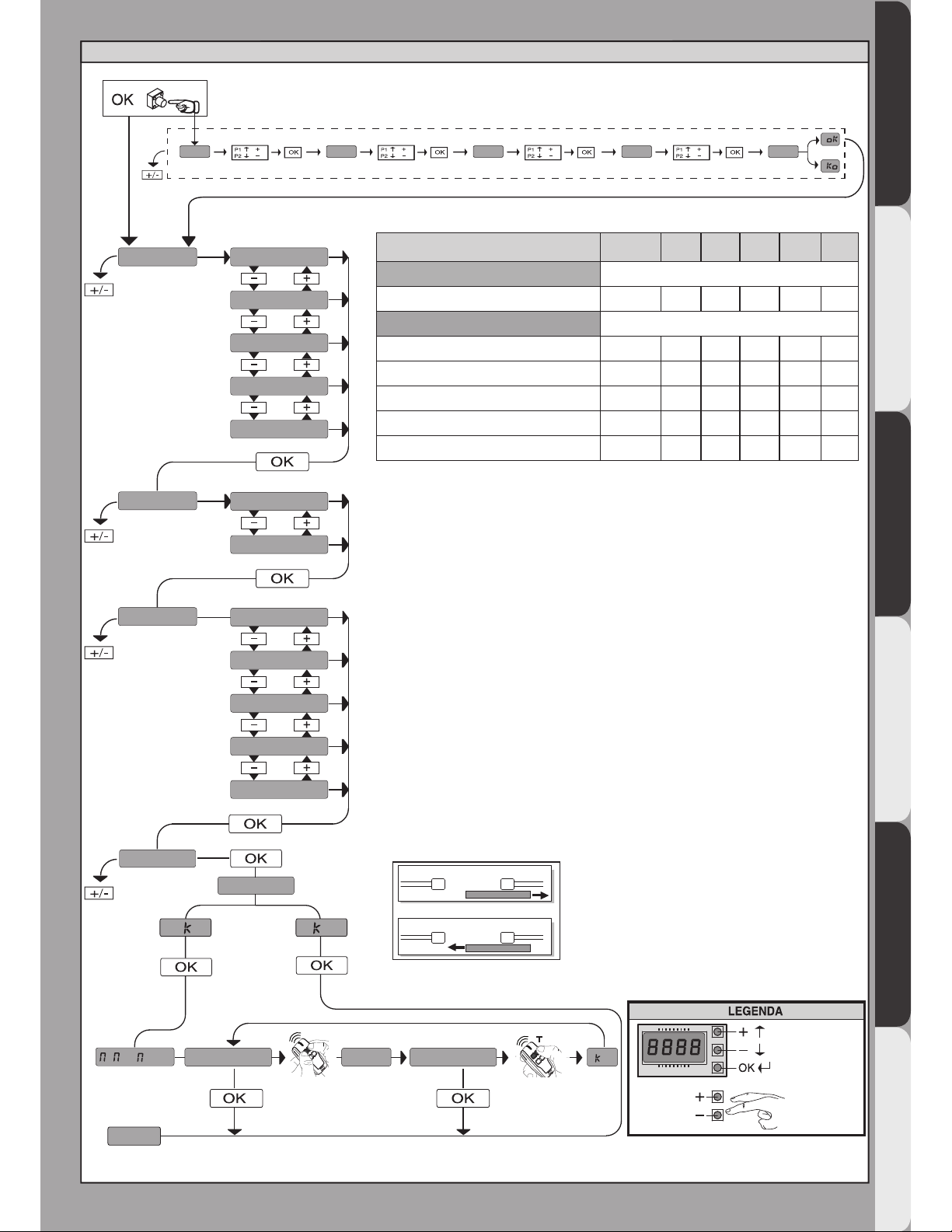
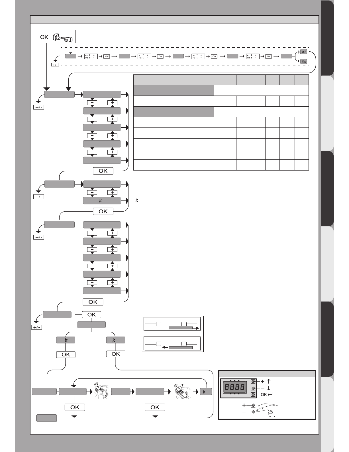
G
!
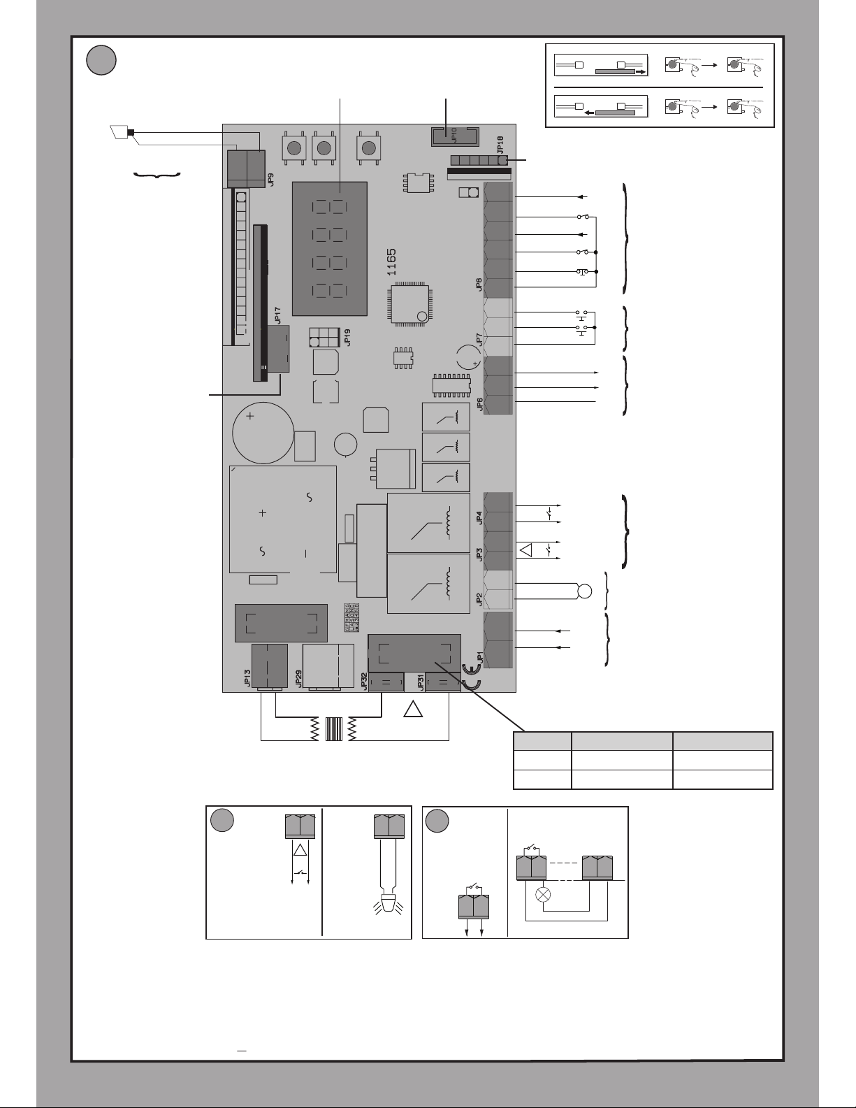
Connettore programmatore palmare,
Palmtop programmer connector,
Connecteur programmateur de poche,
Steckverbinder Palmtop-Programmierer,
Conector del programador de bolsillo,
Connector programmeerbare palmtop.
Connettore scheda opzionale,
Optional board connector,
Connecteur carte facultative,
Steckverbinder Zusatzkarte,
Conector de la tarjeta opcional,
Connector optionele kaart.
Display + tasti programmazione,
Display plus programming keys,
Acheur et touches de programmation,
Display und Programmierungstasten,
Pantalla mas botones de programacion,
Display meerdere toetsen programmeur.
Connettore necorsa
Limit switch connector
Connecteur de n de course
Steckverbindung Endschalter
Conector nal de carrera
Connector eindaanslag
F3 1,25A T
F1
AUX 3 = 0
AUX 3 = 2
AUX 3 = 3
AUX 3 = 4
AUX 3 = 5
AUX 3 = 6
AUX 3 = 7
AUX 3 = 8
AUX 3 = 9
AUX 3 = 10
AUX 0 = 0
AUX 0 = 2
AUX 0 = 3
AUX 0 = 4
AUX 0 = 5
AUX 0 = 7
AUX 0 = 8
AUX 0 = 9
AUX 0 = 10
AUX 0 = 6 AUX 3 = 1
2
1
24 V
SCA
!
24V
20 21
AUX0 - 24V
(MAX 1A)
20 21
26 27
24V 26 27 50 51
Y#
10L N 11 20 21 26 27 50 51 52 60 61 62 70 71 72 73 74 75
Alimentazione / Power supply
Alimentation / Stromversorgung
Alimentación /Voeding
LN
220-230V ~
*
M1
+
-Motore / Motor / moteur
Motor /Eindaanslag/Encoder
AUX 3
(MAX 24V 1A)
AUX
24V -
24V +
24 VSafe+
COM
IC 1
IC 2
NO
NO
Alimentazione accessori
Accessories power supply
Alimentation des accessoires
Stromversorgung Zubehör
Alimentación accesorios
Voeding accessoires
Comandi / Commands
Commandes/Bedienelemente
Mandos/ Commando's
SAFE 1
STOP
COM
FAULT 1
SAFE 2
FAULT 2
NC
NC
NC
Sicurezze
Safety devices
Sécurités
Sicherheitsvorrichtungen
Dispositivos de seguridad
Veiligheden
S1
S2
S3
+
-
OK
24V~ 220-230V~*
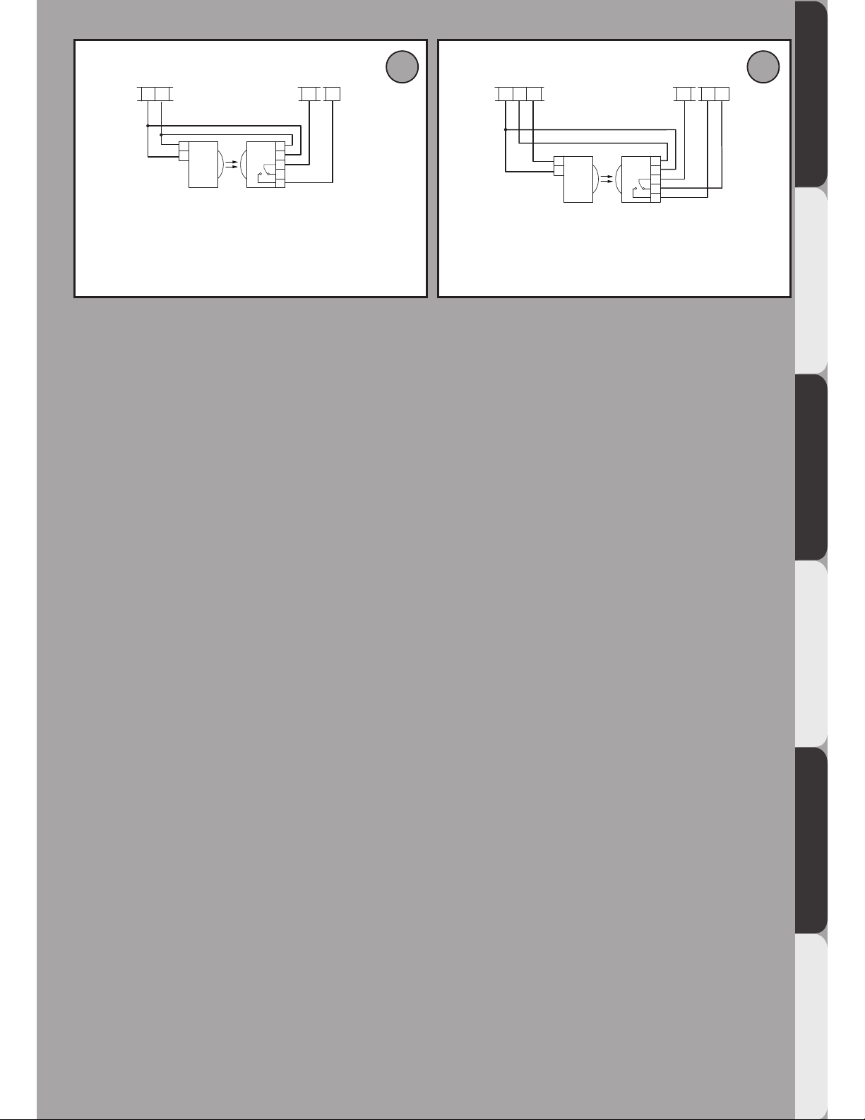
!
AUX 0 - 24V
(MAX 1A)
24V
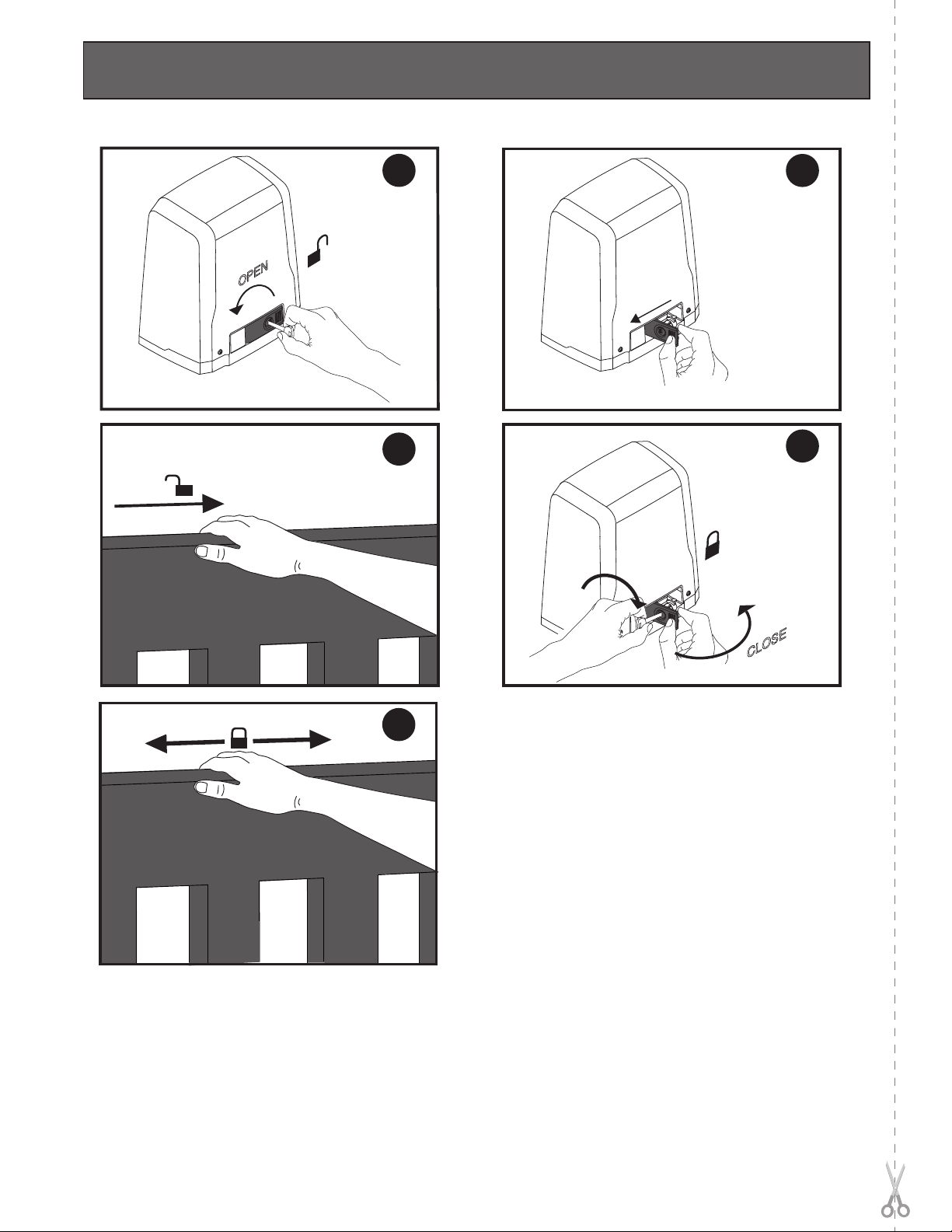
OPEN
CLOSE
S1
S2
+S1
+
-S2
-
X1
X1 X1
X1
OPEN
CLOSE STOP
STOP
**Con logica inversione direzione di apertura = 000 (DIR=DX)
**With reverse logic, opening direction = 000 (DIR=right)
** Avec logique inversion direction d’ouverture = 000 (DIR=DRT)
**Mit Inversionslogik Ö nungsrichtung = 000 (DIR=rechts)
**Con lógica inversión dirección de apertura = 000 (DIR=DER)
**Met logica omkering openingsrichting = 000 (DIR=R)
**
ANT.
ANT
SHIELD
F1
DEIMOS ULTRA BT A 400 DEIMOS ULTRA BT A 600
110-120V 1,6AT 1,6AT
220-230V 0,8AT 1AT
Antenna
Antenne
Antena
Antenne
4 - DEIMOS ULTRA BT A 400 - DEIMOS ULTRA BT A 600
D811980 00100_13