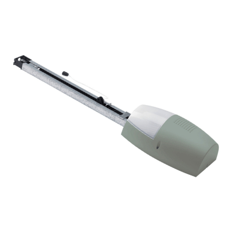
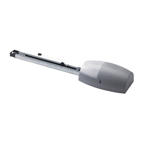
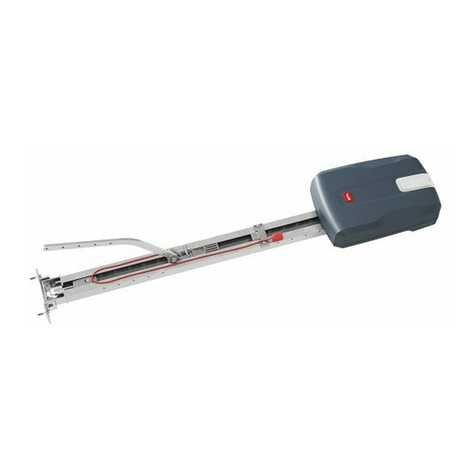
BFT BOTTICELLI B CRC 480 D01 User manual

ISTRUZIONI D’USO E DI INSTALLAZIONE
INSTALLATION AND USER’S MANUAL
INSTRUCTIONS D’UTILISATION ET D’INSTALLATION
INSTALLATIONS-UND GEBRAUCHSANLEITUNG
INSTRUCCIONES DE USO Y DE INSTALACION
GEBRUIKS- EN INSTALLATIEAANWIJZINGEN
BOTTICELLI
B CRC 480 D01
D811882 00100_03 16-07-12
AUTOMAZIONI PER PORTE BASCULANTI E SEZIONALI
AUTOMATION FOR OVERHEAD AND SECTIONAL GARAGE DOORS
AUTOMATION POUR PORTES BASCULANTES ET SECTIONALES
GARAGENTORANTRIEB FÜR SCHWING UND SEKTIONALTORE
AUTOMATIZACIONES PARA PUERTAS BASCULANTE Y SECCIONALES
AUTOMATISERINGEN VOOR KANTEL- EN SECTIEDEUREN
Attenzione! Leggere attentamente le “Avvertenze” all’interno! Caution! Read “Warnings” inside carefully! Attention! Veuillez lire attentivement les Avertissements qui se trouvent à l’intérieur!
Achtung! Bitte lesen Sie aufmerksam die„Hinweise“ im Inneren! ¡Atención¡ Leer atentamente las“Advertencias”en el interior! Let op! Lees de“Waarschuwingen”aan de binnenkant zorgvuldig!
8027908 410481

Eventuali passaggi per cavi,
Possible cable passages,
Passages éventuels pour les câbles,
Eventuelle Kabelführungen,
Eventuales accesos para cables,
Eventuele doorgangen voor kabels
A
B DC
E
1
FGH
BIN
108 mm
166 mm
N.
Configurazione di fissaggio
Fastening conguration
Conguration de la xation
Kongurierung Befestigung
Conguración de jación
Conguratie van bevestiging
1DFBBFD
2DCFFCD
3DCGGCD
4FBBF
5EAAE
6EBBE
7GBBG
A
A
D
B
E
E
F
F
G
B
D
C
C
7x0,5 mm2
LINEA 3x1,5 mm
2
2x0,5 mm2
5x0,5 mm2
INSTALLAZIONE VELOCE-QUICK INSTALLATION-INSTALLATION RAPIDE
SCHNELLINSTALLATION-INSTALACIÓN RÁPIDA - SNELLE INSTALLATIE
2 - BOTTICELLI B CRC 480 D01
D811882 00100_03

ITALIANO ENGLISH FRANÇAIS ESPAÑOL
NEDERLANDS
DEUTSCH
K
M
I J
1
2
3
4
C1
P1
5
L1
L2
C
C
D
D
B
A
D
Tassello / Plug / Cheville
Dübel / Taco / Plug.
Ø 10
V1
V2
V1
4
8
V2
16
4,8
V4
V5 V6
V6
R1 R1
R2
D1
D1
D2
R2
8,4
8,4
8
616
8 6,3
8
60
60
V5
D1 V6
D2 V4
V3
6
20
V3
V3
V5
R1
R2 R1
R2
R2 V5
BOTTICELLI B CRC 480 D01 - 3
D811882 00100_03

N
O
P
R
Q
S
Dima per taglio (scala 1:1) / Cutting template (scale 1:1),
Gabarit de coupage (échelle 1:1),Schneidschablone (Maßstab 1 :1),
Plantilla para corte (escala 1:1) / Kalibervoor snijden (schaal 1:1)
88
1
2
34
5
2
4
1
3
E14 24V
25W max
253.16
65
3
7
8
35
3
380
-
2
78
0
3
7
6
0
-
3
1
60
2
5
0
1
4
6
17
V1
V1
V2
4,8
4,8
16
8
4
V1
4
8
V1
V1
8
30
V1
V2
4 - BOTTICELLI B CRC 480 D01
D811882 00100_03

T
Fig.T1
36710111213
36710111213
DIP TEST PHOT= ON
DIP TEST PHOT= ON
U
ERROR!
12 3 45
REGOLAZIONE FINECORSA, LIMIT DEVICE SETTING,ÉGLAGE FIN DE COURSE, EINSTELLUNG DER ENDSCHALTER,
REGULACION DEL GRUPO DE FIN DE CARRERA, REGELING EINDAANSLAG.
CHIUSURA
CLOSING
FERMETURE
SCHLIESSUNG
CIERRE
SLUITING
APERTURA
OPENING
OUVERTURE
ÖFFNUNG
APERTURA
OPENING
reg fc
o
close prg open prg
Fig.T2
36710111213
DIP TEST PHOT= OFF
24VSafe~MAX 180mA
SCA / 2CH (NO)
24V
~
MAX 180mA
3 12456789101112131415
ANT
SHIELD
Luce di cortesia
Courtesy Light,
Lampe de courtoisie,
Hilfsbeleuchtung,
Luz interior, waaklicht.
Fusibile,Fuse,Fusible,
Schmelzsicherung,Fusible,
Zekering:
COM
PED
1617
JP10
JP2
Connettore scheda opzionale
Optional board connector
Connecteur carte facultative
Steckverbinder Zusatzkarte
Conector de la tarjeta opcional
Connector optionele kaart
Display + tasti programmazione
Display + programming keys
Acheur + touches programmation
Display + Programmierungstasten
Pantalla + botones programación
Display + programmeringstoetsen
Connettore programmatore palmare,
Palmtop programmer connector,
Connecteur programmateur de poche,
Steckverbinder Palmtop-Programmierer,
Conector del programador de bolsillo,
Connector programmeerbare palmtop.
6A B
V1
V1
13
4,2
1 AT
BOTTICELLI B CRC 480 D01 - 5
D811882 00100_03

V
Y
Z1
1 2 3
2 41 3
SWC AUTO
OPEN
AUTO
CLOSE
SWO
AUTOSET COPPIA APERTURA / CHIUSURA, OPENING / CLOSING TORQUE AUTOSETTING, RÉGLAGE AUTOMATIQUE COUPLE OUVERTURE / FERMETURE,
AUTOSET DREHMOMENT ÖFFNUNG / SCHLIESSUNG, AJUSTE AUTOMATICO DEL PAR EN FASE DE APERTURA / CIERRE, ZELFINSTELLING KOPPEL OPENING.
autoset . . . . . .
1 2 3 4
Radiocomando già memorizzato
Radio transmitter already memorised
Radiocommande déjà mémorisée
Bereits gespeicherte Funksteuerung
Radiomando ya memorizado
Reeds gememoriseerde afstandsbediening
Radiocomando già memorizzato
Radio transmitter already memorised
Radiocommande déjà mémorisée
Bereits gespeicherte Funksteuerung
Radiomando ya memorizado
Reeds gememoriseerde afstandsbediening
Radiocomando da memorizzare
Radio transmitter to memorise
Radiocommande à mémoriser
Zu speichernde Funksteuerung
Radiomando que memorizar
Te memoriseren afstandsbediening
Radiocomando da memorizzare
Radio transmitter to memorise
Radiocommande à mémoriser
Zu speichernde Funksteuerung
Radiomando que memorizar
Te memoriseren afstandsbediening
X
SCS1 SCS1 SCS1
Max. 250m
TX1
TX2
RX1
RX2
TX1
TX2
RX1
RX2
TX1
TX2
RX1
RX2
Z
ON
OFF
ON
3 12456789101112131415
JP2
16
17
JP10
A
1 2
6 - BOTTICELLI B CRC 480 D01
D811882 00100_03

ACCESSO AI MENU Fig. 1
x 2
autoset
reg. fc.
o
fine 35.40 Soglia ostacolo
Forza istantanea motore
Codice
diagnoistica
Descrizione Note
STRt Attivazione ingresso start START
STOP Attivazione ingresso STOP
PHOT Attivazione ingresso fotocellula PHOT
SWO Attivazione ingresso FINECORSA APERTURA
SWc Attivazione ingresso FINECORSA CHIUSURA
ped Attivazione ingresso PEDONALE
open Attivazione ingresso OPEN
CLS Attivazione ingresso CLOSE
amp Inversione per ostacolo Vericareeventualiostacolilungo
il percorso
ER01 Test fotocellule fallito Verificare collegamento foto-
cellule e/o impostazioni logiche
ER10 Errore test hardware scheda Rivelati problemi al circuito di
comando motore
ER11 Errore test hardware scheda Rilevati problemi al circuito di
lettura corrente motore
ITALIANO
BOTTICELLI B CRC 480 D01 - 7
D811882 00100_03

AVVERTENZE PER L’INSTALLATORE
Tutto quello che non è espressamente previsto nel manuale d’in-
stallazione, non è permesso. ll buon funzionamento dell’operatore
è garantito solo se vengono rispettati i dati riportati. La ditta non
risponde dei danni causati dall’inosservanza delle indicazioni ripor-
tate in questo manuale.
Lasciandoinalteratelecaratteristicheessenziali delprodotto,laDitta
si riserva di apportare in qualunque momento le modiche che essa
ritiene convenienti per migliorare tecnicamente, costruttivamente
e commercialmente il prodotto, senza impegnarsi ad aggiornare la
presente pubblicazione.
ATTENZIONE! Importanti istruzioni di sicurezza. Leggere e seguire atten-
tamente tutte le avvertenze e le istruzioni che accompagnano il prodotto
poiché un’installazione errata può causare danni a persone, animali o cose.
Leavvertenzeeleistruzionifornisconoimportantiindicazioniriguardantila
sicurezza, l’installazione, l’uso e la manutenzione. Conservare le istruzioni
per allegarle al fascicolo tecnico e per consultazioni future.
SICUREZZA GENERALE
Questo prodotto è stato progettato e costruito esclusivamente per l’utilizzo
indicato in questa documentazione. Usi diversi da quanto indicato potrebbero
essere causa di danni al prodotto e di pericolo.
-Gli elementi costruttivi della macchina el’installazionedevonoessere in accordo
con le seguenti Direttive Europee, ove applicabili: 2004/108/CE, 2006/95/CE,
2006/42/CE, 89/106/CE, 99/05/CE e loro modiche successive. Per tutti i Paesi
extra CEE, oltre alle norme nazionali vigenti, per un buon livello di sicurezza è
opportuno rispettare anche le norme citate.
-La Ditta costruttrice di questo prodotto (di seguito “Ditta”) declina qualsiasi
responsabilità derivante da un uso improprio o diverso da quello per cui è
destinato e indicato nella presente documentazione nonché dall’inosservanza
della BuonaTecnica nella costruzione delle chiusure (porte, cancelli, ecc.) e dalle
deformazioni che potrebbero vericarsi durante l’uso.
-Prima di installare il prodotto apportare tutte le modiche strutturali relative
alle realizzazione dei franchi di sucurezza a alla protezione o segregazione di
tutte le zone di schiacciamento, cesoiamento, convogliamento e di pericolo in
genere, secondo quanto previsto dalle norme EN 12604 ed 12453 o eventuali
normelocalidi installazione.Vericareche la struttura esistenteabbiainecessari
requisiti di robustezza e stabilità.
-Prima di iniziare l’installazione vericare l’integrità del prodotto.
-La Ditta non è responsabile della inosservanza della Buona Tecnica nella costru-
zione e manutenzione degli inssi da motorizzare, nonché delle deformazioni
che dovessero intervenire nell’utilizzo.
-Vericare che l’intervallo di temperatura dichiarato sia compatibile con il luogo
destinato all’installazione dell’automazione.
-Non installare questo prodotto in atmosfera esplosiva: la presenza di gas o fumi
inammabili costituisce un grave pericolo per la sicurezza.
- Togliere l’alimentazione elettrica, prima di qualsiasi intervento sull’impianto.
Scollegare anche eventuali batterie tampone se presenti.
-Primadicollegarel’alimentazioneelettrica,accertarsicheidatiditargacorrispon-
dano ai quelli della rete di distribuzione elettrica e che a monte dell’impianto
elettrico vi siano un interruttore dierenziale e una protezione da sovracorrente
adeguati.Prevederesullaretedialimentazionedell’automazione,uninterruttore
ounmagnetotermicoomnipolarecondistanzadiaperturadeicontatticonforme
a quanto previsto dalle norme vigenti.
-Vericare che a monte della rete di alimentazione, vi sia un interruttore dieren-
ziale con soglia non superiore a 0.03A e a quanto previsto dalle norme vigenti.
-Vericare che l’impianto di terra sia realizzato correttamente: collegare a terra
tutte le parti metalliche della chiusura (porte, cancelli, ecc.) e tutti i componenti
dell’impianto provvisti di morsetto di terra.
-L’installazione deve essere fatta utilizzando dispositivi di sicurezza e di comandi
conformi alla EN 12978 e EN12453.
-Le forze di impatto possono essere ridotte mediante l’utilizzo di bordi deforma-
bili.
-Nel caso in cui le forze di impatto superino i valori previsti dalle norme, applicare
dispositivi elettrosensibili o sensibili alla pressione.
-Applicaretuttii dispositivi di sicurezza (fotocellule,coste sensibili, ecc.) necessari
a proteggere l’area da pericoli di impatto, schiacciamento, convogliamento,
cesoiamento. Tenere in considerazione le normative e le direttive in vigore,
i criteri della Buona Tecnica, l’utilizzo, l’ambiente di installazione, la logica di
funzionamento del sistema e le forze sviluppate dall’automazione.
-Applicare i segnali previsti dalle normative vigenti per individuare le zone
pericolose (i rischi residui). Ogni installazione deve essere identicata in modo
visibile secondo quanto prescritto dalla EN13241-1.
- Successivamente al completamento dell’installazione, applicare una targa
identicativa della porta/cancello
-Questo prodotto non può essere installato su ante che incorporano delle porte
(a meno che il motore sia azionabile esclusivamente a porta chiusa).
-Se l’automazione è installata ad una altezza inferiore a 2,5 m o se è accessibile,
è necessario garantire un adeguato grado di protezione delle parti elettriche e
meccaniche.
-Installare qualsiasi comando sso in posizione tale da non causare pericoli e
lontano da parti mobili. In particolare i comandi a uomo presente devono essere
posizionati in vista diretta della parte guidata, e, a meno che non siano a chiave,
devono essere installati a una altezza minima di 1,5 m e in modo tale da non
essere accessibili al pubblico.
-Applicare almeno un dispositivo di segnalazione luminosa (lampeggiante) in
posizione visibile, ssare inoltre alla struttura un cartello di Attenzione.
-Fissareinmodopermanenteunaetichettarelativaalfunzionamentodellosblocco
manuale dell’automazione e apporla vicino all’organo di manovra.
-Assicurarsi che durante la manovra siano evitati o protetti i rischi meccanici ed
in particolare l’impatto, lo schiacciamento, il convogliamento, il cesoiamento tra
parte guidata e parti circostanti.
-Dopo aver eseguito l’installazione, assicurarsi che il settaggio dell’automazione
motore sia correttamente impostato e che i sistemi di protezione e di sblocco
funzionino correttamente.
-Usare esclusivamente parti originali per qualsiasi manutenzione o riparazione.
La Ditta declina ogni responsabilità ai ni della sicurezza e del buon funziona-
mento dell’automazione se vengono impiegati componenti di altri produttori.
-Non eseguire alcuna modica ai componenti dell’automazione se non espres-
samente autorizzata dalla Ditta.
-Istruirel’utilizzatoredell’impiantoperquantoriguardaglieventualirischiresidui,
i sistemi di comando applicati e l’esecuzione della manovra apertura manuale
in caso di emergenza: consegnare il manuale d’uso all’utilizzatore nale.
-Smaltireimaterialidi imballo (plastica, cartone,polistirolo,ecc.)secondo quanto
previstodalle normevigenti.Non lasciare buste di nylone polistirolo alla portata
dei bambini.
COLLEGAMENTI
ATTENZIONE! Per il collegamento alla rete utilizzare: cavo multipolare di sezione
minima 5x1,5mm2o 4x1,5mm2per alimentazioni trifase oppure 3x1,5mm2per
alimentazioni monofase (a titolo di esempio, il cavo può essere del tipo H05VV-F
con sezione 4x1.5mm2). Per il collegamento degli ausiliari utilizzare conduttori
con sezione minima di 0,5 mm2.
-Utilizzare esclusivamente pulsanti con portata non inferiore a 10A-250V.
-I conduttori devono essere vincolati da un ssaggio supplementare in prossi-
mità dei morsetti (per esempio mediante fascette) al ne di tenere nettamente
separate le parti in tensione dalle parti in bassissima tensione di sicurezza.
-
Il cavo di alimentazione, durante l’installazione, deve essere sguainato in modo da
permettereilcollegamentodelconduttorediterraall’appropriatomorsettolasciando
però i conduttori attivi il più corti possibile. Il conduttore di terra deve essere l’ultimo
a tendersi in caso di allentamento del dispositivo di ssaggio del cavo.
ATTENZIONE! i conduttori a bassissima tensione di sicurezza devono essere
sicamente separati dai conduttori a bassa tensione.
L’accessibilità alle parti in tensione deve essere possibile esclusivamente per il
personale qualicato (installatore professionale)
VERIFICA DELL’AUTOMAZIONE E MANUTENZIONE
Primadirenderedenitivamenteoperatival’automazione,edurantegliinterventi
di manutenzione, controllare scrupolosamente quanto segue:
-Vericare che tutti i componenti siano ssati saldamente;
-Vericare l’operazione di avvio e fermata nel caso di comando manuale.
-Vericare la logica di funzionamento normale o personalizzata.
-
Solo per cancelli scorrevoli: vericare il corretto ingranamento cremagliera -
pignone con un gioco di 2 mm lungo tutta la cremagliera; tenere la rotaia di
scorrimento sempre pulita e libera da detriti.
-Solo per cancelli e porte scorrevoli: vericare che il binario di scorrimento del
cancello sia lineare, orizzontale e le ruote siano idonee a sopportare il peso del
cancello.
-Solo per cancelli scorrevoli sospesi (Cantilever): vericare che non ci sia abbas-
samento o oscillazione durante la manovra.
-Solo per cancelli a battente: vericare che l’asse di rotazione delle ante sia
perfettamente verticale.
-Controllareilcorrettofunzionamentodi tuttiidispositividisicurezza(fotocellule,
coste sensibili, ecc) e la corretta regolazione della sicurezza antischiacciamento
vericando che il valore della forza d’impatto misurato nei punti previsti dalla
norma EN 12445, sia inferiore a quanto indicato nella norma EN 12453.
-Leforzediimpattopossonoessereridottemediantel’utilizzodibordideformabili.
-Vericare la funzionalità della manovra di emergenza ove presente.
-Vericare l’operazione di apertura e chiusura con i dispositivi di comando appli-
cati.
-Vericare l’integrità delle connessioni elettriche e dei cablaggi, in particolare lo
stato delle guaine isolanti e dei pressa cavi.
-Durante la manutenzione eseguire la pulizia delle ottiche delle fotocellule.
-Peril periodo difuori servizio dell’automazione,attivarelo sbloccodi emergenza
(vedi paragrafo “MANOVRA DI EMERGENZA”) in modo da rendere folle la parte
guidata e permettere così l’apertura e la chiusura manuale del cancello.
-Se il cavo di alimentazione è danneggiato, esso deve essere sostituito dal co-
struttore o dal suo servizio di assistenza tecnica o comunque da una persona
con qualica similare, in modo da prevenire ogni rischio.
-Se si si installano dispositivi di tipo “D” (come deniti dalla EN12453), collegati
in modalità non vericata, prescrivere una manutenzione obbligatoria con
frequenza almeno semestrale.
ATTENZIONE!
Ricordarsichelamotorizzazioneèunafacilitazionedell’usodelcancello/portaenon
risolveproblemi a difettiedecienze di installazione o di mancatamanutenzione.
DEMOLIZIONE
L’eliminazione dei materiali va fatta rispettando le norme vigenti. Nel caso di
demolizione dell’automazione non esistono particolari pericoli o rischi derivanti
dall’automazione stessa.
Èopportuno, in caso di recuperodei materiali,che vengano separati per tipologia
(parti elettriche - rame - alluminio - plastica - ecc.).
SMANTELLAMENTO
Nel caso l’automazione venga smontata per essere poi rimontata in altro sito
bisogna:
-Togliere l’alimentazione e scollegare tutto l’impianto elettrico.
-Togliere l’attuatore dalla base di ssaggio.
-Smontare tutti i componenti dell’installazione.
-Nel caso alcuni componenti non possano essere rimossi o risultino danneggiati,
provvedere alla loro sostituzione.
AVVERTENZE PER L’INSTALLATORE D811766_06
8 - BOTTICELLI B CRC 480 D01
D811882 00100_03
ITALIANO
1) GENERALITÀ
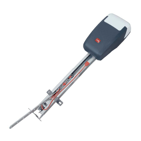
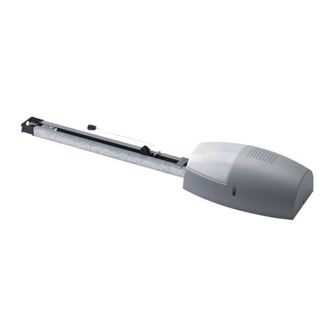
Il sistema BOTTICELLI B CRC 480 D01 è adatto a motorizzare porte sezionali
(Fig.C), porte basculanti debordanti a molle a totale rientranza (Fig.B) e porte
basculanti a contrappesi mediante un apposito braccio di traino (Fig.D). L’altezza
massimadellaportabasculantenondevesuperarei3metri.L’installazionedifacile
esecuzione, permette un rapido montaggio senza alcuna modica alla porta. Il
blocco in chiusura è mantenuto dal motoriduttore irreversibile.
2) DATI TECNICI
ATTUATORE
Alimentazione 230V ~±10%, 50/60Hz Monofase (*)
Tensione motore 24V
Potenzamax. assorbita dalla rete 180W
Lubricazione Grasso permanente
Forza trazione e spinta 800 N
Corsa utile BINARIO L.=2900 corsa utile=2400 mm (**)
BINARIO L.=3500 corsa utile=3000 mm (***)
Velocità media 5 m/min
Reazione all’urto Limitatore di coppia integrato su quadro
comando
Manovre in 24 ore 20
Finecorsa Elettronico ad ENCODER
Luce cortesia Lampada 24V
~
25W max, E14
Temperatura di funzionamento -15°C / +60°C
Grado di protezione IPX0
Peso testamotore 5 kg
Rumorosità <70dB(A)
Dimensioni Vedi g.1
QUADRO COMANDO
Alimentazione accessori 24V~ (180mA max)
24Vsafe (180mA max)
Regolazione limitatore di coppia In chiusura e apertura
Collegamento lampeggiante 24V~ max 25W
Tempo di accensione lampada
di servizio 90s
Radioricevente Rolling-Code
incorporata Frequenza 433.92 MHz
Codica Algoritmo Rolling-Code
N° combinazioni 4 miliardi
Impedenza antenna 50 Ohm (RG58)
N°maxradiocomandimemorizzabili
63
Fusibili vedi Fig.T
(*) Disponibile in tutte le tensioni di rete.
(**) Ruotando la testa del motore di 90° (Fig.N), la corsa utile diventerà 2580 mm.
(***) Ruotando la testa del motore di 90° (Fig.N), la corsa utile diventerà 3180 mm.
Versioni trasmettitori utilizzabili:
Tutti i trasmettitori ROLLING CODE compatibili con
3) PREDISPOSIZIONE IMPIANTO ELETTRICO Fig.A
Predisporre l’arrivo dei collegamenti degli accessori, dei dispositivi di sicurezza
e di comando al gruppo motore tenendo nettamente separati i collegamenti a
tensione di rete dai collegamenti in bassissima tensione di sicurezza (24V). Pro-
cedere al loro collegamento come indicato nello schema elettrico.
I cavi di connessione accessori devono essere protetti da canaletta (g.K rif.5C1).
4) INSTALLAZIONE DELL’ATTUATORE
4.1) Veriche preliminari:
• Controllareilbilanciamentodellaporta.
• Controllareloscorrimentodellaportapertuttalacorsa.
• Selaportanonèdinuovainstallazione,controllarelostatodiusuradituttii
componenti.
• Sistemareosostituirelepartidifettoseousurate.
• L’adabilitàelasicurezzadell’automazioneèdirettamenteinuenzatadallo
stato della struttura della porta.
• Primadiinstallareilmotore,togliereeventualifuniocatenesuperueedisa-
bilitare qualsiasi apparecchiatura non necessaria.
4.2) Montaggio
1) Togliere dalla cremonese della porta il catenaccio di blocco esistente.
2) Montare la staa a muro in metallo con le viti di serie sulla staa porta bina-
rio (Fig.E1). Le viti non devono essere ssate, la staa deve poter ruotare.
3) Anchèil binario vengassatocorrettamente,segnarela mezzeria della
porta,posizionareilBINasottoesegnareifori(Fig.F).
Fare attenzione che la distanza tra il binario e il telo della porta sia compresa
tra 108 e 166 mm(vedi g.G).Se non si rispetta questa altezza utilizzare le
stae in dotazione.
La tabella di Fig. H rappresenta le varie combinazioni per ssare la staa al
portone basculante.
4) ForareilsottoconunapuntaD.10rispettandoiriferimentiprecedente-
mente segnati e inserire i tasselli Fig. I.
5) Bloccare il binario alla base g.J (rif.1-2) e g.K (rif.3-4-5).
6) Con l’aiuto di un appoggio adeguato, alzare l’intero motore, avvitare le viti
alla staa porta binario senza ssarle al telaio della porta (Fig.L1) o, se l’al-
tezza lo consente, montare la staa ssandola all’architrave in muratura con
tasselli (Fig.L2).
7) Alzarelatestamotorizzatanoadappoggiareiltuttoalsottoeinserirvi
le viti di ssaggio che bloccano il binario (comprese le viti della staa di
ancoraggio).
8)
Nel caso in cui il ssaggio della testa motore e del binario non fossero ssati
direttamentealsottovedereFig.M(bisognasemprecontrollarelaplanarità
del binario e la sua perpendicolarità).
9) Nel caso in cui il binario fosse girato di 90° rispetto alla testa motore, usare la
dima di riferimento di Fig. N1 per tagliare il carter seguendo le misure indica-
te.PerilssaggioasottodelBINvedereFig.Fenelcasoincuiilbinarionon
fossessatodirettamentealsotto,vedereFig.E.
10)
Nel caso in cui il binario fosse in due metà vedere Fig.O, per i vari tipi di
ssaggi vedere gure precedenti.
11) Sbloccare il carrello e ssare le stae di ancoraggio al telo della porta (Fig.H).
La distanza fra binario e sezionale può andare da 108 a 166 mm. Se è più
grande è necessario utilizzare le stae e abbassare il motore, se è più piccola
è necessario accorciare il piatto di trascinamento.
12) Applicare gli adesivi forniti in prossimità dei punti pericolosi Fig.Q.
5) REGOLAZIONE TENDICATENA (BOTTICELLI B CRC 480 D01)
L’automazione viene fornita già tarata e collaudata. Nel caso necessiti aggiustare
la tensione della catena agire come indicato in g.R.
ATTENZIONE: il gommino antistrappo non deve mai essere completamente
compresso. Vericare scrupolosamente che il gommino non vada in totale
compressione durante il funzionamento.
6) SBLOCCO MANUALE (Vedi MANUALE D’USO -FIG.1-).
6.1) SOSTITUZIONE LAMPADINA (FIG.2)
----------------------------------------------------------
7) COLLEGAMENTI MORSETTIERA (FIG.T)
MORSETTO DESCRIZIONE
JP2 cablaggio trasformatore
JP10 cablaggio motore
1-2 Ingresso antenna per scheda radioricevente integrata
(1: CALZA. 2: SEGNALE)
3-4 Ingresso START (N.O.)
3-5 Ingresso STOP (N.C.) Se non si utilizza lasciare il pon-
ticello inserito.
3-6 Ingresso FOTOCELLULA (N.C.) Se non si utilizza lascia-
re il ponticello inserito.
3-7 Ingresso FAULT (N.O.)
Ingresso per fotocellule dotate di contatto N.O. di verica
8-9 Uscita 24 V~ per luce lampeggiante (25 W max)
10-11 Uscita 24V~ 180mA max - alimentazione fotocellule o
altri dispositivi.
12-13 Uscita24V~Vsafe180mAmax-alimentazionetrasmet-
titori fotocellule con verica.
14-15
Uscitaspiacancelloaperto(ContattoNO)/2°canaleradio.
16-17 Ingresso APERTURA PARZIALE (N.O.)
8) DISPOSITIVI DI SICUREZZA
Nota: utilizzare solamente dispositivi di sicurezza riceventi con contatto
in libero scambio.
8.1) DISPOSITIVI VERIFICATI Fig. T1
8.2) COLLEGAMENTO DI 1 COPPIA DI FOTOCELLULE NON VERIFICATE Fig. T2
9 ACCESSO AI MENU: FIG. 1
9.1) MENU PARAMETRI PARA TABELLA“A”PARAMETRI
9.2) MENU LOGICHE LOGICTABELLA“B”LOGICHE
9.3) MENU RADIO radio TABELLA“C”RADIO
- NOTA IMPORTANTE: CONTRASSEGNARE IL PRIMO TRASMETTITORE
MEMORIZZATO CON IL BOLLINO CHIAVE (MASTER).
Il primo trasmettitore, nel caso di programmazione manuale, assegna il CODICE
CHIAVE DELLA RICEVENTE; questo codice risulta necessario per poter eettuare
la successiva clonazione dei radiotrasmettitori.
La ricevente di bordo incorporato Clonix dispone inoltre di alcune importanti
funzionalità avanzate:
• Clonazionedeltrasmettitoremaster(rolling-codeocodicesso).
• Clonazionepersostituzioneditrasmettitorigiàinseritinellaricevente.
• Gestionedatabasetrasmettitori.
• Gestionecomunitàdiricevitori.
Per l’utilizzo di queste funzionalità avanzate fate riferimento alle istruzioni del pro-
grammatore palmare universale ed alla Guida generale programmazioni riceventi.
9.4 MENU DEFAULT default
Riporta la centrale ai valori preimpostati dei DEFAULT. Dopo il ripristino è neces-
sario eettuare un nuovo AUTOSET.
MANUALE PER L’INSTALLAZIONE
BOTTICELLI B CRC 480 D01 - 9
D811882 00100_03

MANUALE PER L’INSTALLAZIONE
TABELLA “A”- MENU PARAMETRI - (param)
Parametro Min. Max.
Default Personali
Denizione Descrizione
TCA 1 180 40 Tempo chiusura
automatica [s] Impostarenumericamenteilvaloredeltempodiaperturaautomaticada1a180secondi.
Coppia Ap 1 99 50
Coppia apertura [%]
Impostare il valore di coppia di apertura del motore tra 1% e 99%.
ATTENZIONE: Verificare che il valore della forza d’impatto
misurato nei punti previsti dalla norma EN12445, sia inferiore a quanto
indicato nella norma EN 12453.
Una errata impostazione della sensibilità può creare danni
a persone, animali o cose.
coppia ch 1 99 50 Coppia chiusura
[%]
Impostare il valore di coppia di chiusura del motore tra 1% e 99%.
ATTENZIONE: Verificare che il valore della forza d’impatto
misurato nei punti previsti dalla norma EN12445, sia inferiore a quanto
indicato nella norma EN 12453.
Una errata impostazione della sensibilità può creare danni
a persone, animali o cose.
ap. parz.
000.1
006.0 001.0
Apertura parziale [m]
Impostare numericamente il valore di apertura parziale da 10 cm (000,1) a 6 mt. (006.0)
zona 0 127 0 Zona Impostare il numero di zona tra un valore minimo di 0 ed un valore massimo di 127.
Vedi paragrafo“Connessione seriale”.
vel. ap 70 99 99 Velocità a regime
in apertura [%] Imposta la velocità massima in apertura che raggiunge l’attuatore a regime.
Il valore è espresso in percentuale sulla velocità massima raggiungibile dall’attuatore.
vel ch 70 99 99 Velocità a regime
in chiusura [%] Imposta la velocità massima in chiusura che raggiunge l’attuatore a regime.
Il valore è espresso in percentuale sulla velocità massima raggiungibile dall’attuatore.
spazio
rall 7 100 7 Spazio di
rallentamento [cm] Imposta lo spazio di rallentamento in apertura e in chiusura che esegue l’attuatore.
La modica di uno di questi parametri:
- Velocità a regime in apertura
- Velocità a regime in chiusura
- Spazio di rallentamento
comporta una manovra completa dell’attuatore eseguita senza controllo antischiacciamento. Questa manovra è contraddistinta dal lampeggio sul display della
scritta “SET”.
9.5 MENU LINGUA lingua
Consente di impostare la lingua del programmatore a display.
9.6 MENU AUTOSET AUTOset FIG.V
•
Dare avvio ad una operazione di autosettaggio portandosi nell’apposito menu.
• NonappenapremutoilpulsanteOKvienevisualizzatoilmessaggio“............”,
la centrale comanda una manovra di apertura seguita da una manovra di
chiusura, durante la quale viene automaticamente settato il valore minimo di
coppia necessario al movimento dell’anta.
Durante questa fase è importante evitare l’oscuramento delle fotocellule,
nonchè l’utilizzo dei comandi START, STOP e del display.
Altermine di questa operazionelacentraledi comandoavràautomaticamente
impostato i valori ottimali di coppia. Vericarli ed eventualmente modicarli
come descritto in programmazione.
ATTENZIONE!! Verificare che il valore della forza d’impatto
misuratoneipuntiprevistidallanormaEN12445,siainferiore a quanto
indicato nella norma EN 12453.
Attenzione!! Durante l’autosettaggio la funzione di rileva
mentoostacolinonèattiva,l’installatoredevecontrollareilmovimento
dell’automazione ed impedire a persone o cose di avvicinarsi o sostare nel
raggio di azione dell’automazione.
9.7) MENU REGOLAZIONE FINECORSA FIG. U
Il quadro comandoVENERE D dispone di un menu di regolazione dei necorsa di
apertura e chiusura che semplica la procedura di installazione.
Procedere come segue:
• Dareavvioadunaoperazionediregolazionenecorsaportandosinell’apposito
menu del quadro VENERE D (Fig. A).
• Allavisualizzazionedelmessaggio“CLOSE”,portarel’antanellaposizionedi
chiusuradesideratautilizzandoipulsanti“UP”e“DOWN”dellacentrale,tenendo
presente che il pulsante“DOWN” chiude l’anta, mentre il pulsante“UP” apre
l’anta.
Appena l’anta si trova nella posizione di chiusura desiderata premere il pulsante
“OK”in modo da memorizzare la posizione di necorsa chiusura.
• Allavisualizzazionedelmessaggio“OPEN”,portarel’antanellaposizionedi
aperturadesideratautilizzandoipulsanti“UP”e“DOWN”dellacentraletenendo
presente che il pulsante“DOWN” chiude l’anta, mentre il pulsante“UP” apre
l’anta.
Appena l’anta si trova nella posizione di apertura desiderata premere il pulsante
“OK”in modo da memorizzare la posizione di necorsa apertura.
• Posizionarecorrettamenteessareconlevitiil“bloccacarrello”aridossodel
carrello (g.U rif.6 A-B).
NOTA: Queste manovre vengono eseguite in modalità“uomo presente”
a velocità ridotta e senza l’intervento delle sicurezze.
9.8) STATISTICHE
Collegato il programmatore PALMARE UNIVERSALE alla centralina, entrare nel
menù CENTRALE / STATISTICHE e scorrere la schermata dei parametri statistici:
- Versione software microprocessore scheda.
- Numero cicli eettuati. Se si sostituiscono i motori, annotarsi il numero di
manovre eseguite no a quel momento.
- Numero cicli eettuati dall’ultima manutenzione. Viene azzerato auto-
maticamente ad ogni autodiagnosi o scrittura parametri.
- Dataultima manutenzione.Daaggiornaremanualmentedall’appositomenù
“ Aggiorna data di manutenzione”.
- Descrizione impianto. Permette di inserire 16 caratteri di individuazione
impianto.
10) PROGRAMMAZIONE TRASMETTITORI REMOTA FIG. X
Questa modalità non richiede l’accesso al quadro di comando.
11) CONNESSIONE SERIALE MEDIANTE SCHEDA SCS1 (Fig.Y)
Il quadro di comando VENERE D consente, tramite appositi ingressi e uscite
seriali (SCS1), la connessione centralizzata di più automazioni. In questo modo
è possibile, con un unico comando, eseguire l’apertura o la chiusura di tutte le
automazioni connesse.
SeguendoloschemadiFig.Y,procedereallaconnessioneditutti iquadricomando
VENERE D, utilizzando esclusivamente un doppino di tipo telefonico.
Nelcasosiutilizziuncavotelefonicoconpiùcoppierisultaindispensabileutilizzare
i li della stessa coppia.
La lunghezza del cavo telefonico fra una apparecchiatura e la successiva
non deve eccedere i 250 m.
Aquestopuntoènecessariocongurareopportunamenteogniquadrocomando
VENERE D, impostando inanzitutto una centrale MASTER, che avrà il controllo di
tutte le altre, necessariamente settate come SLAVE (vedi menu logiche).
Impostare inoltre il numero di Zona (vedi menu parametri) tra 0 e 127.
Il numero di zona consente di creare dei gruppi di automazioni, ognuna delle
quali risponde al Master di Zona. Ognizonapuòavereun solo Master,ilMaster
della zona 0 controlla anche gli Slave delle altre zone.
12) SOSTITUZIONE FUSIBILE FIG. Z
13) ACCESSORI FIG. Z1
SM1 Sblocco esterno da applicare alla cremonese esistente della porta bascu-
lante (1).
SET/S Sblocco esterno a maniglia rientrante per porte sezionali max. 50mm (2).
ST Sblocco automatico catenacci per porte basculanti a molle. Applicato al
braccettodi comando,sgancia automaticamente i catenaccilateralidella
porta (3).
10 - BOTTICELLI B CRC 480 D01
D811882 00100_03
MANUALE PER L’INSTALLAZIONE
TABELLA “B” - LOGICHE - (LOGIC)
Logica Denizione
Default
Barrare
il
settaggio
eseguito
Opzioni
TCA Tempo Chiusura
Automatica OFF ON Attiva la chiusura automatica
OFF Esclude la chiusura automatica
3 PASSI
Abilita la logica 3
passi.
OFF
0N Logica 3 passi mov. passo passo
3 PASSI 4 PASSI
CHIUSA APRE APRE
IN
CHIUSURA
STOP
APERTA
CHIUDE CHIUDE
IN APERTURA
STOP + TCA STOP + TCA
DOPO STOP
APRE APRE
OFF Logica 4 passi
BlImp AP Blocca Impulsi
apertura OFF ON L’impulso di start non ha alcun eetto durante la fase di apertura.
OFF L’impulso di start ha eetto durante la fase di apertura.
preAll Pre allarme OFF ON Il lampeggiante si accende circa 3 secondi prima della partenza del motore.
OFF Il lampeggiante si accende contemporaneamente alla partenza dei motori.
fotoc ap Fotocellule in
apertura OFF
ON in caso di oscuramento, esclude il funzionamento della fotocellula in apertura. In fase di chiusura,
inverte immediatamente.
OFF in caso di oscuramento, le fotocellule sono attive sia in apertura che in chiusura. Un oscuramento
della fotocellula in chiusura, inverte il moto solo dopo il disimpegno della fotocellula.
test phot Test fotocellule OFF ON Attiva la verica delle fotocellule
OFF Disattiva la verica delle fotocellule
SCA 2Ch
Spia cancello
aperto o II° canale
radio
OFF ON
L’uscita tra i morsetti 14-15 viene congurata come Spia cancello aperto, il II° canale radio in questo
caso comanda l’apertura parziale.
OFF L’uscita tra i morsetti
14-15
viene congurata come II° canale radio.
codice fisso Codice Fisso OFF
ON Il ricevitore risulta congurato per il funzionamento in modalità codice sso, vedi paragrafo“Clona-
zione dei Radiotrasmettitori”
OFF Il ricevitore risulta congurato per il funzionamento in modalità rolling-code, vedi paragrafo
“Clonazione dei Radiotrasmettitori”
prog. radio
Programmazione
radiocomandi ON
ON
Abilita la memorizzazione via radio dei trasmettitori:
1- Premere in sequenza il tasto nascosto (P1) e il tasto normale (T1-T2-T3-T4) di un trasmettitore
già memorizzato in modalità standard attraverso il menu radio.
2- Premere entro 10s il tasto nascosto (P1) ed il tasto normale (T1-T2-T3-T4) di un trasmettitore
da memorizzare.
La ricevente esce dalla modalità programmazione dopo 10s, entro questo tempo è possibile
inserire ulteriori nuovi trasmettitori.
Questa modalità non richiede l’accesso al quadro comando.
OFF Disabilita la memorizzazione via radio dei trasmettitori.
I trasmettitori vengono memorizzati solo utilizzando l’apposito menu Radio.
start-open Selezione
START - OPEN OFF ON L’ingresso tra i due morsetti 3-4 funziona come OPEN.
OFF L’ingresso tra i due morsetti 3-4 funziona come START.
ped-close Selezione
PED-CLOSE OFF ON L’ingresso tra i due morsetti 16-17 funziona come CLOSE.
OFF L’ingresso tra i due morsetti 16-17 funziona come APERTURA PARZIALE.
master Master/Slave OFF ON Il quadro comando viene settato come Master in un collegamento centralizzato.
OFF Il quadro comando viene settato come Slave in un collegamento centralizzato.
TABELLA“C” MENU RADIO RADIO
Logica Descrizione
Agg start Aggiungi Tasto start
associa il tasto desiderato al comando Start
Agg 2ch
Aggiungi Tasto 2ch
associa il tasto desiderato al comando 2° canale radio. Se nessuna uscita è congurata come Uscita 2° canale radio, il 2° canale radio comanda
l’apertura pedonale.
elim. 64
Elimina Lista
ATTENZIONE! Rimuove completamente dalla memoria della ricevente tutti i radiocomandi memorizzati.
cod RX Lettura codice ricevitore
Visualizza il codice ricevitore necessario per la clonazione dei radiocomandi.
v
ON = Abilita la programmazione a distanza delle schede tramite un trasmettitore W LINK precedentemente memorizzato.
Questa abilitazione rimane attiva 3 minuti dall’ultima pressione del radiocomando W LINK.
OFF= Programmazione W LINK disabilitata.
ITALIANO
BOTTICELLI B CRC 480 D01 - 11
D811882 00100_03

ACCESS MENUS Fig. 1
x 2
autoset
Exit Menù
Conrm/
Switch on display
Scroll up
Scroll down
See PARAMETERS MENU
See LOGIC MENU
See RADIO MENU
add. start
hidden butt
hidden butt
release
release
desired button
desired button
Add. 2ch
erase 64
language
o
END
l.sw adj
35.40
Obstacle threshold
Instantaneous force motor
Diagnostics code DESCRIPTION NOTES
STRt START input activated
STOP STOP input activated
PHOT PHOT input activated
SWO OPENING LIMIT SWITCH input activated
SWc CLOSING LIMIT SWITCH input activated
ped PEDESTRIAN input activated
open OPEN input activated
CLS CLOSE input activated
AMP Reverse due to obstacle Check for obstacles in path
ER01 Photocell test failed
Check photocell connection and/or logic settings
ER10 Board hardware test error Problems detected in motor’s control circuit
ER11 Board hardware test error Problems detected in motor’s current reading
circuit
12 - BOTTICELLI B CRC 480 D01
D811882 00100_03

INSTALLER WARNINGS
Anything that is not explicitly provided for in the installation ma-
nual is not allowed. The operator’s proper operation can only be
guaranteed if the information given is complied with. The Firm shall
not be answerable for damage caused by failure to comply with the
instructions featured herein.
While we will not alter the product’s essential features, the Firm re-
serves the right, at any time, to make those changes deemed oppor-
tune to improve the product from a technical, design or commercial
point of view, and will not be required to update this publication
accordingly.
WARNING! Important safety instructions. Carefully read and comply with
all the warnings and instructions that come with the product as incorrect
installationcan cause injurytopeopleand animalsanddamagetoproperty.
Thewarningsandinstructionsgiveimportantinformationregardingsafety,
installation,use and maintenance.Keep holdofinstructions so thatyou can
attach them to the technical le and keep them handy for future reference.
GENERAL SAFETY
This product has been designed and built solely for the purpose indicated herein.
Uses other than those indicated herein might cause damage to the product and
create a hazard.
-Theunitsmakingupthemachineanditsinstallationmustmeettherequirements
of the following European Directives, where applicable: 2004/108/EC, 2006/95/
EC, 2006/42/EC, 89/106/EC, 99/05/EC and later amendments. For all countries
outside the EEC, it is advisable to comply with the standards mentioned, in ad-
dition to any national standards in force, to achieve a good level of safety.
-The Manufacturer of this product (hereinafter referred to as the“Firm”) disclaims
all responsibility resulting from improper use or any use other than that for
which the product has been designed, as indicated herein, as well as for failure
to apply Good Practice in the construction of entry systems (doors, gates, etc.)
and for deformation that could occur during use.
-Before installing the product, make all structural changes required to produce
safety gaps and to provide protection from or isolate all crushing, shearing and
dragging hazard areas and danger zones in general in accordance with the
provisions of standards EN 12604 and 12453 or any local installation standards.
Check that the existing structure meets the necessary strength and stability
requirements.
-Before commencing installation, check the product for damage.
-The Firm is not responsible for failure to apply Good Practice in the construction
and maintenance of the doors, gates, etc. to be motorized, or for deformation
that might occur during use.
-Make sure the stated temperature range is compatible with the site in which the
automated system is due to be installed.
-Donotinstallthisproductinanexplosiveatmosphere:thepresenceofammable
fumes or gas constitutes a serious safety hazard.
-Disconnect the electricity supply before performing any work on the system.
Also disconnect buer batteries, if any are connected.
-Before connecting the power supply, make sure the product’s ratings match the
mains ratings and that a suitable residual current circuit breaker and overcurrent
protection device have been installed upline from the electrical system. Have
the automated system’s mains power supply tted with a switch or omnipolar
thermal-magnetic circuit breaker with a contact separation that meets code
requirements.
-Make sure that upline from the mains power supply there is a residual current
circuit breaker that trips at no more than 0.03A as well as any other equipment
required by code.
-Make sure the earth system has been installed correctly: earth all the metal parts
belonging to the entry system (doors, gates, etc.) and all parts of the system
featuring an earth terminal.
-Installation must be carried out using safety devices and controls that meet
standards EN 12978 and EN 12453.
-Impact forces can be reduced by using deformable edges.
-Intheeventimpact forcesexceedthe values laiddownby therelevantstandards,
apply electro-sensitive or pressure-sensitive devices.
-Apply all safety devices (photocells, safety edges, etc.) required to keep the
area free of impact, crushing, dragging and shearing hazards. Bear in mind the
standards and directives in force, Good Practice criteria, intended use, the instal-
lation environment, the operating logic of the system and forces generated by
the automated system.
-Apply all signs required by current code to identify hazardous areas (residual
risks).Allinstallationsmustbevisiblyidentiedin compliancewiththeprovisions
of standard EN 13241-1.
-Once installation is complete, apply a nameplate featuring the door/gate’s data.
-Thisproduct cannotbeinstalled onleavesincorporatingdoors(unlessthemotor
can be activated only when the door is closed).
-If the automated system is installed at a height of less than 2.5 m or is accessible,
the electrical and mechanical parts must be suitably protected.
-Install any xed controls in a position where they will not cause a hazard, away
from moving parts. More specically, hold-to-run controls must be positioned
withindirectsightofthe partbeingcontrolledand, unless they arekey operated,
must be installed at a height of at least 1.5 m and in a place where they cannot
be reached by the public.
-Apply at least one warning light (ashing light) in a visible position, and also
attach a Warning sign to the structure.
-Attach a label near the operating device, in a permanent fashion, with informa-
tion on how to operate the automated system’s manual release.
-Make sure that, during operation, mechanical risks are avoided or relevant
protective measures taken and, more specically, that nothing can be banged,
crushed, caught or cut between the part being operated and surrounding parts.
-Once installation is complete, make sure the motor automation settings are
correct and that the safety and release systems are working properly.
-Only use original spare parts for any maintenance or repair work. The Firm dis-
claims all responsibility for the correct operation and safety of the automated
system if parts from other manufacturers are used.
-Do not make any modications to the automated system’s components unless
explicitly authorized by the Firm.
-Instruct the system’s user on what residual risks may be encountered, on the
control systems that have been applied and on how to open the system manu-
ally in an emergency. give the user guide to the end user.
-Dispose of packaging materials (plastic, cardboard, polystyrene, etc.) in accord-
ance with the provisions of the laws in force. Keep nylon bags and polystyrene
out of reach of children.
WIRING
WARNING! Forconnection tothemainspowersupply,use:amulticorecable with
a cross-sectional area of at least 5x1.5mm2or 4x1.5mm2when dealing with three-
phase power supplies or 3x1.5mm2for single-phase supplies (by way of example,
type H05 VV-F cable can be used with a cross-sectional area of 4x1.5mm2).To con-
nect auxiliary equipment, use wires with a cross-sectional area of at least 0.5mm2.
- Only use pushbuttons with a capacity of 10A-250V or more.
- Wiresmustbesecuredwithadditionalfasteningneartheterminals(forexample,
using cable clamps) in order to keep live parts well separated from safety extra
low voltage parts.
- During installation, the power cable must be stripped to allow the earth wire
to be connected to the relevant terminal, while leaving the live wires as short
as possible. The earth wire must be the last to be pulled taut in the event the
cable’s fastening device comes loose.
WARNING! safety extra low voltage wires must be kept physically separate from
low voltage wires.
Only qualied personnel (professional installer) should be allowed to access
live parts.
CHECKING THE AUTOMATED SYSTEM AND MAINTENANCE
Beforetheautomatedsystemisnallyputintooperation,andduringmaintenance
work, perform the following checks meticulously:
-Make sure all components are fastened securely.
-Check starting and stopping operations in the case of manual control.
-Check the logic for normal or personalized operation.
-For sliding gates only: check that the rack and pinion mesh correctly with 2 mm
of play along the full length of the rack; keep the track the gate slides on clean
and free of debris at all times.
-For sliding gates and doors only: make sure the gate’s running track is straight
and horizontal and that the wheels are strong enough to take the weight of the
gate.
-For cantilever sliding gates only: make sure there is no dipping or swinging
during operation.
-For swing gates only: make sure the leaves’axis of rotation is perfectly vertical.
-Check that all safety devices (photocells, safety edges, etc.) are working properly
and that the anti-crush safety device is set correctly, making sure that the force
of impact measured at the points provided for by standard EN 12445 is lower
than the value laid down by standard EN 12453.
-Impact forces can be reduced by using deformable edges.
-Make sure that the emergency operation works, where this feature is provided.
-Check opening and closing operations with the control devices applied.
-Check that electrical connections and cabling are intact, making extra sure that
insulating sheaths and cable glands are undamaged.
-While performing maintenance, clean the photocells’optics.
-When the automated system is out of service for any length of time, activate the
emergency release (see“EMERGENCY OPERATION”section) so that the operated
part is made idle, thus allowing the gate to be opened and closed manually.
-
If the power cord is damaged, it must be replaced by the manufacturer or their
technical assistance department or other such qualied person to avoid any risk .
-If “D” type devices are installed (as dened by EN12453), connect in unveried
mode, foresee mandatory maintenance at least every six months
WARNING!
Remember that the drive is designed to make the gate/door easier to use and
will not solve problems as a result of defective or poorly performed installation
or lack of maintenance
SCRAPPING
Materials must be disposed of in accordance with the regulations in force.There
areno particularhazardsorrisksinvolvedin scrapping the automatedsystem.For
the purpose of recycling, it is best to separate dismantled parts into like materials
(electrical parts - copper - aluminium - plastic - etc.).
DISMANTLING
Ifthe automatedsystemisbeingdismantledinordertobereassembledatanother
site, you are required to:
-Cut o the power and disconnect the whole electrical system.
-Remove the actuator from the base it is mounted on.
-Remove all the installation’s components.
-See to the replacement of any components that cannot be removed or happen
to be damaged.
AVVERTENZE PER L’INSTALLATORE D811766_06
ENGLISH
BOTTICELLI B CRC 480 D01 - 13
D811882 00100_03

INSTALLATION MANUAL
1) GENERAL OUTLINE
TheBOTTICELLIBCRC480D01systemis suitable formotorisingsectionaldoors
(g. C), protruding fully retracting spring-operated overhead doors (g. B) and
counterweightoverheaddoors providedwith an appropriatetowingarm(g.D).
The overhead door must not be higher than 3 metres. Its easy installation allows
fast tting without needing the door to be modied.The irreversible gearmotor
keeps the door locked in the closing position.
2) TECHNICAL SPECIFICATIONS
ATTUATORE
Power supply 230V ~±10%, 50/60Hz single-phase (*)
Motor voltage 24V
Max.powerabsorbedfrommains 180W
Lubrication permanent grease
Towing and pushing force 800 N
Working stroke
BINARIOL.=2900 working stroke=2400mm(**)
BINARIOL.=3500workingstroke=3000mm(***)
Average speed 5 m/min
Impact reaction integrated torque limiter on control panel
Manoeuvres in 24 hours 20
Limit switch Electronic with ENCODER
Courtesy light 24V
~
25W max, E14 bulb
Working temperature -15°C / +60°C
Degree of protection IPX0
Motor head weight 5 kg
Noise level <70dB(A)
Dimensions see g.1
CONTROL PANEL
Supply to accessories 24V~ (180mA max)
24Vsafe (180mA max)
Torque limiter setting on closing and opening
Blinker connection 24V~ max 25W
Service light switching-on time 90s
Incorporated rolling-code radio
receiver Frequency 433.92 MHz
Coding rolling-code algorithm
No. combinations 4 milliard
Antenna impedance 50 Ohm (RG58)
Max no. radio controls to be
memorised 63
Fuses see gure T
(*) Available in all mains voltages.
(**)By turning the motor head by 90° (Fig.N) the useful stroke will be 2580 mm.
(***)By turning the motor head by 90° (Fig.N) the useful stroke will be 3180 mm.
Usable transmitter versions:
All ROLLING CODE transmitters compatible with
3)
ELECTRICAL INSTALLATION SET-UP
Fig.A
Arrange for the connections of accessories and safety and control devices to
reach the motor unit, keeping the mains voltage connections clearly separate
from the extra low safety voltage connections (24V).
Proceed to connection following the indications given in the wiring diagram.
The cables for connecting the accessories must be protected by a raceway (g.
K ref. 5C1).
4) ACTUATOR INSTALLATION
4.1) Preliminary checks
• Checkthatthedoorisbalanced.
• Checkthatthedoorslidessmoothlyalongitsentiretravel.
• Ifthedoorhasnotbeennewlyinstalled,checkthewearconditionofallits
components.
• Repairorreplacefaultyorwornparts.
• Theautomationreliabilityandsafetyaredirectlyinuencedbythestateof
the door structure.
• Beforettingthemotor,removeanysuperuousropesorchainsanddisable
any unnecessary appliances.
4.2) FITTING
1) Remove the existing locking bolt from the cremone bolt of the door.
2) Fit the metal wall bracket to the track-holder bracket using the screws sup-
plied as standard (Fig.E1). The screws must not be tightened, so that the
bracket can be rotated.
3) In order for the track to be correctly xed, mark the mid-point of the door,
position the BIN onto the ceiling and mark the holes (Fig.F).
Make sure that the distance between the track and the door panel is com-
prised between 108 and 166 mm (see Fig.G). The table in Fig. H gives the
various combinations for fastening the bracket to the overhead door.
4) Drill the ceiling using a D.10 bit, with reference to the markings made previ-
ously, and insert the plugs. Fig. I.
5) Secure the track at the base, g.J (1-2), K (3-4-5).
6) With the help of an adequate support, lift the entire motor, screw the screws
onto the track-holding bracket without xing them to the door frame (Fig.
L1) or, if the height allows it, t the bracket to the masonry lintel by means
of plugs (Fig.L2).
7) Rest the motor onto the oor (taking care not to damage it) and x the
articulated bracket to the door frame or to the ceiling.
8) In the case where the motor is not directly xed to the ceiling, t the brack-
ets as shown in Fig.M, after marking and drilling the holes with reference to
the brackets.
9) In the case where the track is turned by 90° with respect to the motor head,
use the reference template in Fig. N1 to cut out the guard, keeping to the
measurements indicated. For track tting to the ceiling, see Fig.F (for tracks
tted lower, see Fig.E).
10) In the case where the track is made in two halves, see Fig.O; for the dierent
types of xing methods, see the previous gures.
11)
Release the carriage and x the anchoring brackets to the door panel (Fig.H).
The distance allowed between track and sectional door is 108 to 166 mm.
In case of greater distance, it is necessary to use the brackets and lower the
motor; in case of shorter distance, it is necessary to shorten the towing plate.
12) Stick the adhesive labels supplied next to the dangerous points (Fig. Q).
5) CHAIN TIGHTENER ADJUSTMENT (BOTTICELLI B CRC 480 D01)
The operator supplied is already calibrated and inspected. Should the chain ten-
sion need to be adjusted, proceed as shown in g. R.
WARNING: the anti-tear rubber element must never be completely com-
pressed. Scrupulously check that the rubber does not become totally com-
pressed during operation.
6) MANUAL RELEASE (See USER GUIDE -FIG.1-).
6.1) REMPLACEMENT DE L’AMPOULE (FIG.2)
----------------------------------------------------------
7) TERMINAL BOARD CONNECTIONS (FIG.T)
TERMINAL DESCRIPTION
JP2 transformer wiring
JP10 motor wiring
1-2 Antenna input for integrated radio-receiver board
(1: BRAID. 2: SIGNAL)
3-4 START input (N.O.)
3-5 STOP input (N.C.) If not used, leave the jumper inserted.
3-6
PHOTOCELL input (N.C.) If not used, leave the jumper inserted.
3-7 FAULT input (N.O.)
Input for photocells provided with checking N.O. contact
8-9 24 V~ output for blinking light (25 W max)
10-11 24V~ 180mA max output – power supply for photocells or
other devices.
12-13 24V~ Vsafe 180mA max output – power supply for checking
photocell transmitters.
14-15 PARTIAL OPENING input
16-17 Ingresso APERTURA PARZIALE (N.O.)
8) SAFETY DEVICES
Note: only use receiving safety devices with free changeover contact.
8.1) TESTED DEVICES Fig. T1
8.2) CONNECTION OF 1 PAIR OF NONTESTED PHOTOCELLS Fig. T2
9 CALLING UP MENUS: FIG. 1
9.1) PARAMETERS MENU PARA PARAMETERS TABLE “A”
9.2) LOGIC MENU LOGICLOGIC TABLE“B”
9.3) RADIO MENU radio RADIO TABLE“C”
- IMPORTANT NOTE: THE FIRST TRANSMITTER MEMORIZED MUST BE
IDENTIFIED BY ATTACHING THE KEY LABEL (MASTER).
In the event of manual programming, the rst transmitter assigns the RECEIVER’S
KEY CODE: this code is required to subsequently clone the radio transmitters.
The Clonix built-in on-board receiver also has a number of important advanced features:
• Cloningofmastertransmitter(rollingcodeorxedcode).
• Cloningtoreplacetransmittersalreadyenteredinreceiver.
• Transmitterdatabasemanagement.
• Receivercommunitymanagement.
To use these advanced features, refer to the universal handheld programmer’s
instructions and to the general receiver programming guide.
9.4 MENU DEFAULT default
Restores the controller’s DEFAULT factory settings. Following this reset, you will
need to run the AUTOSET function again.
14 - BOTTICELLI B CRC 480 D01
D811882 00100_03
INSTALLATION MANUAL
9.5 MENU LINGUA lingua
Used to set the programmer’s language on the display.
9.6 MENU AUTOSET AUTOset FIG.V
•
Launch an autoset operation by going to the relevant menu.
•
As soon as you press the OK button, the“.... .... ....”message is displayed and the control
unit commands the device to perform a full cycle (opening followed by closing), dur-
ing which the minimum torque value required to move the leaf is set automatically.
During this stage, it is important to avoid breaking the photocells’beams and not
to use the START and STOP commands or the display.
Once this operation is complete, the control unit will have automatically set the
optimumtorquevalues.Checkthemand,wherenecessary,editthemasdescribed
in the programming section.
WARNING!! Check that the force of impact measured at the points
provided for by standard EN 12445 is lower than the value laid down
by standard EN 12453.
Warning!!Whiletheautosetfunctionisrunning,theobstacledetection
function is not active. Consequently, the installer must monitor the
automatedsystem’smovementsandkeeppeopleand propertyoutofrange
of the automated system.
9.7) MENU REGOLAZIONE FINECORSA FIG. U
The VENERE D control panel has an opening and closing limit switch adjustment
menu, which simplies the installation procedure.
Proceed as follows:
• Launchalimitswitchadjustmentoperationbygoingtotherelevantmenu
on the VENERE D panel (Fig.B).
• Whenthe“CLOSE”messageisdisplayed,movethedoortothedesiredclosed
position using the “UP” and “DOWN” buttons on the control unit, bearing in
mind that the “DOWN”button closes the door, while the “UP” button opens
the door. As soon as the door is in the desired closed position, press the“OK”
button to store the closed travel limit position.
• Whenthe“OPEN”messageisdisplayed,movethedoortothedesiredopen
position using the “UP” and “DOWN” buttons on the control unit, bearing in
mind that the “DOWN”button closes the door, while the “UP” button opens
the door.
As soon as the door is in the desired open position, press the“OK” button to
store the open travel limit position.
• Positionthe“runnerstop”correctlyupagainsttherunnerandsecureinplace
with the screws (g.U rif.6 A-B).
NOTE:Theseoperationsmustbeperformedin“deadman”modeatreduced
speed and without the safety devices operating.
9.8) STATISTICS
Connect the UNIVERSAL HANDHELD programmer to the control unit, enter the
CONTROLUNIT/STATISTICSmenuandrunthroughthestatisticsparametersscreen:
- Software version of card microprocessor.
- Number of cycles performed. If the motors are replaced, write down the
number of operations performed so far.
- Number of cycles performed since last service. Automatically reset every time
self-diagnosis is run or parameters are written.
- Dateoflast service.Mustbeupdatedmanuallyviatherelevant“Updateservice
date”menu
- System description. Allows for 16 characters to be entered to identify the
system.
10) REMOTE TRANSMITTER PROGRAMMING FIG. X
This mode does not require access to the control panel.
11) SERIAL CONNECTION VIA SCS1 CARD (Fig.Y)
The VENERE D control panel’s special serial inputs and outputs (SCS1) make the
centralizedconnectionofanumberofautomateddevicespossible.Thatway,allthe
automated devices connected can be opened or closed with a single command.
Connect all VENERE D control panels using twisted pair cabling only, proceeding
as shown in the diagram in Fig. Y.
When using a telephone cable with more than one pair, it is essential to use wires
from the same pair.
The length of the telephone cable between one unit and the next must not
be greater than 250 m.
Atthispoint,each VENERE D controlpanel needsto be conguredappropriately,
starting by entering a MASTER control panel that will have control over all the
others, which therefore have to be set as SLAVE units (see logic menu).
Also set the Zone number (see parameters menu) in the range 0 to 127.
The zone number allows you to create groups of automated devices, each of
which answers to the Zone Master. Each zone can have only one Master: the
Master of zone 0 also controls the Slaves of the other zones.
12) FUSE REPLACEMENT FIG. Z
13) ACCESSORIES FIG. Z1
SM1 External release device to be applied to the cremone bolt already tted
to the overhead door (1).
SET/S External release device with retracting handle for sectional doors mea-
suring max 50mm (2).
ST Automaticboltreleasedeviceforspring-operatedoverheaddoors.Fitted
to the control arm, it automatically releases the side door bolts (3).
TABLE“A” PARAMETERS MENU - PARA
Parameter min. max. Default
Personal
Denition Description
TCA 1 180 40 Automatic
Closing Time [s] Set the numerical value of the automatic opening time in the range 1 to 180 seconds.
Op.Torque 1 99 50 Opening torque
[%]
Set the numerical value of the motor’s opening torque in the range 1% to 99%
.
WARNING:Checkthattheforceofimpactmeasuredatthepointsprovidedfor
bystandardEN12445islowerthanthevaluelaiddownbystandardEN12453.
Setting sensitivity incorrectly can result in damage to property and injury to
people and animals.
Cls.Torque 1 99 50 Closing torque
[%]
Set the numerical value of the motor’s closing torque in the range 1% to 99%.
WARNING:Checkthattheforceofimpactmeasuredatthepointsprovidedfor
bystandardEN12445islowerthanthevaluelaiddownbystandardEN12453.
Setting sensitivity incorrectly can result in damage to property and injury to
people and animals.
part.open
000.1
006.0 001.0 Partial opening
[m]
Set the numerical value of partial opening in the range 10 cm (0.001) to 6 m (006.0)
zona 0 127 0 Zona Set the zone number between a minimum value of 0 and a maximum value of 127.
See section 11 entitled “Serial connection”.
op speed 70 99 99 Running speed
during opening
[%]
Sets the maximum opening speed reached by the actuator at running speed.
The value is given as a percentage of the maximum speed the actuator can reach.
cl speed 70 99 99 Running speed
during closing
[%]
Sets the maximum closing speed reached by the actuator at running speed.
The value is given as a percentage of the maximum speed the actuator can reach.
dist.sloud 7 100 7 Slow-down
distance [cm] Sets the slow-down distance travelled by the actuator during opening and clos-
ing.
Editing one of the following parameters:
- Running speed during opening
- Running speed during closing
- Slow-down distance
resultsintheactuatorperformingacompleteopening/closingcyclewiththeanti-crushfeatureswitchedo.The“SET”messageashesonthedisplaytowarnthat
this cycle is in progress.
ENGLISH
BOTTICELLI B CRC 480 D01 - 15
D811882 00100_03

INSTALLATION MANUAL
TABELLA “B” - LOGICHE - (LOGIC)
Logic Denition
Default
Cross
out
setting
used
Optional extras
TCA Automatic Closing
Time OFF ON Switches automatic closing on
OFF Switches automatic closing o
3 step Switches to 3-step
logic OFF
0N Logic 3 step step-by-step mov.
3 STEP 4 STEP
CLOSED OPENS OPENS
DURING CLOSING
STOPS
OPEN CLOSES CLOSES
DURING OPENING STOP + TCA
STOP + TCA
AFTER STOP OPENS OPENS
OFF Logic 4 step
ibl open Block opening
pulses OFF ON The start pulse has no eect during opening.
OFF The start pulse has eect during opening.
pre-alarm Pre-alarm OFF ON Theashinglightcomesonapprox.3secondsbeforethemotorstarts.
OFF Theashinglightcomesonatthesametimeasthemotorsstart.
Photoc.
open
Photocells during
opening OFF
ON when beam is broken, operation of the photocell is switched o during opening. During clos-
ing, movement is reversed immediately.
OFF when beam is broken, photocells are active during both opening and closing. When beam is
broken during closing, movement is reversed only once the photocell is cleared.
test phot Photocell test OFF ON Switches photocell testing on
OFF Switches photocell testing on
SCA 2Ch Gate open light or
2nd radio channel OFF ON The output between terminals 14-15 is set as Gate open light: in this case, the 2nd radio channel
controls partial opening.
OFF The output between terminals 14-15 is set as 2nd radio channel.
fixed code Fixed Code OFF
ON Receiver is congured for operation in xed-code mode, see“Radio transmitter cloning”section.
OFF Receiver is congured for operation in rolling-code mode, see “Radio transmitter cloning” sec-
tion.
radio prog Remote control
programming ON
ON
Enables wireless memorizing of transmitters:
1- Press in sequence the hidden key (P1) and normal key (T1-T2-T3-T4) of a transmitter that has
already been memorized in standard mode via the radio menu.
2- Press within 10 sec. the hidden key (P1) and normal key (T1-T2-T3-T4) of a transmitter to be
memorized.
The receiver exits programming mode after 10 sec.: you can use this time to enter other new
transmitters.
This mode does not require access to the control panel.
OFF Disables wireless memorizing of transmitters. Transmitters are memorized only using the rel-
evant Radio menu.
start-open START - OPEN
setting OFF ON Input between terminals 3-4 works as OPEN
OFF Input between terminals 3-4 works as START.
ped-close PED-CLOSE setting OFF ON Input between terminals 16-17 works as CLOSE.
OFF Input between terminals 16-17 works as PARTIAL OPENING.
master Master/Slave OFF ON Control panel is set up as the Master unit in a centralized connection system.
OFF Control panel is set up as a Slave unit in a centralized connection system.
TABLE “C” RADIO MENU RADIO
Logic Description
Add start Add Start Key
associates the desired key with the Start command
add 2ch
Add 2ch Key
associates the desired key with the 2nd radio channel command. Associates the desired key with the 2nd radio channel command. If no output
is congured as 2nd Radio Channel Output, the 2nd radio channel controls the pedestrian opening.
erase 64
Erase List
WARNING! Erases all memorized transmitters from the receiver’s memory.
Read receiver code
Displays receiver code required for cloning transmitters.
ON = Enables remote programming of cards via a previously memorized W LINK transmitter.
It remains enabled for 3 minutes from the time the W LINK transmitter is last pressed.
OFF= W LINK programming disabled.
16 - BOTTICELLI B CRC 480 D01
D811882 00100_03

langue
x 2
ACCES AUX MENUS Fig. 1
autoset
Sortir du menu
Allumage aicheur
Descendre
Monter
Confirmation /
Voir MENU PARAMÈTRES
Voir MENU LOGIQUES
Voir MENU RADIO
adj start
touche cachee
touche cachee
relacher
relacher
touche desiree
touche desiree
dj
effacer 64
o
regl fc 35.40 Seuil obstacle
Force instantanée du moteur
Code de diagnostic
Description Remarque
STRt activation entrée START
STOP activation entrée STOP
PHOT activation entrée PHOTOCELLULE
SWO activation entrée FIN DE COURSE OPEN
SWc
activationentréeFINDECOURSEFERMETURE
ped activation entrée PIÉTON
open activation entrée OPEN
CLS activation entrée CLOSE
AMP Inversion pour obstacle
Vérier éventuels obstacles le long du parcours
ER01 Essai photocellules échoué
Vérier connexion photocellules et/ou congurations
logiques
ER10 Erreur essai matériel carte
Détection problèmes du circuit de commande du moteur
ER11 Erreur essai matériel carte
Détection problèmes du circuit de lecture courant moteur
FRANÇAIS
BOTTICELLI B CRC 480 D01 - 17
D811882 00100_03

ATTENTION ! Instructions de sécurité importantes. Veuillez lire et suivre
attentivement tous les avertissements et toutes les instructions fournis
avec le produit sachant qu’une installation incorrecte peut provoquer des
préjudices aux personnes, aux animaux ou aux biens. Les avertissements
fournissentdesindicationsimportantesconcernantlasécurité,l’installation,
l’utilisationetl’entretien.Veuillezconserverlesinstructionspourlesjoindre
au dossier technique et pour d’ultérieures consultations.
SECURITE GÉNÉRALE
Ce produit a été conçu et réalisé exclusivement pour l’usage indiqué dans cette
documentation. Tout usage autre que celui indiqué risque d’endommager le
produit et d’être une source de danger.
-Les éléments qui composent l’appareil et le montage doivent être conformes
aux Directives Européennes suivantes : 2004/108/CE, 2006/95/CE, 2006/42/CE,
89/106/CE, 99/05/CE et leurs modications successives. Pour les pays n’appar-
tenant pas à la CEE, il est conseillé de respecter également les normes citées,
outre les règlements nationaux en vigueur, an de garantir un bon niveau de
sécurité.
-Le Fabricant de ce produit (par la suite « le Fabricant ») décline toute respon-
sabilité dérivant d’un usage incorrect ou diérent de celui prévu et indiqué
dans la présente documentation, de l’inobservation de la bonne technique de
construction des huisseries (portes, portails, etc.) et des déformations pouvant
apparaître à l’usage.
-Avant d’installer le produit apportez toutes les modications structurelles
nécessaires pour réaliser les butées de sécurité et la protection ou ségréga-
tion de toutes les zones présentant un risque d’écrasement, de cisaillement,
d’entraînement ou autre, conformément aux normes EN 12604 et 12453 ou les
éventuelles normes locales sur l’installation. - Vériez si la structure existante
est susamment robuste et stable.
-Avant de commencer le montage, vérier l’intégrité du produit.
-Le fabricant décline toute responsabilité en cas d’inobservation de la bonne
technique de construction et d’entretien des huisseries motorisées, ainsi que
de déformations survenant en cours d’utilisation.
-Vérier si l’intervalle de température déclaré est compatible avec le lieu destiné
à l’installation de l’automatisation.
-Ne pas installer ce produit dans une atmosphère explosive: la présence de gaz
ou de fumées inammables constitue un grave danger pour la sécurité.
-Mettre hors tensions l’installation avant d’accomplir une quelconque interven-
tion. Déconnecter également les batteries tampon éventuellement présentes.
-Avant de mettre hors tension, vérier si les données de la plaque d’identi-
cation correspondent à celles du secteur et s’il y a en amont de l’installation
électrique un disjoncteur et une protection adéquats contre la surintensité.
Prévoir sur le réseau d’alimentation de l’automatisation un interrupteur ou un
magnétothermique omnipolaire ayant une distance d’ouverture des contacts
conforme aux règlements en vigueur.
-Vérier s’il y a en amont du réseau d’alimentation un disjoncteur dont le seuil
ne dépasse pas 0,03A et les prescriptions des règlements en vigueur.
-Vérier si l’installation de mise à la terre est réalisée correctement. Connecter
toutes les parties métalliques de la fermeture (portes, portails, etc..) et tous les
composants de l’installation munis de borne de terre.
-L’installation doit être équipée de dispositifs de sécurité et de commandes
conformes aux normes EN 12978 et EN12453.
-Les forces de choc peuvent être réduites à l’aide de rebords déformables.
-Si les forces de choc dépassent les valeurs prévues par les normes, appliquer
des dispositifs électrosensibles ou sensibles à la pression.
-Appliquer tous les dispositifs de sécurité (photocellules, linteaux sensibles,
etc..) nécessaires pour protéger la zone contre les risques de choc, d’écrase-
ment, d’entraînement ou de cisaillement. Tenir compte des règlements et des
directives en vigueur, des critères de bonne technique, de l’utilisation, de l’envi-
ronnement de l’installation, de la logique de fonctionnement du système et
des forces développées par l’automatisation.
-Appliquer les signaux prévus par les règlements en vigueur pour indiquer les
zones de danger (risques résiduels). Toutes les installations doivent être identi-
ées de façon visible conformément aux prescriptions de EN13241-1.
-Au terme de l’installation, appliquez une plaque d’identication de la porte/du
portail.
-Ce produit ne peut pas être installé sur des vantaux munis de portes (à moins
que le moteur ne puisse être actionné qu’avec la prote fermée).
bSi l’automatisation est installée à une hauteur inférieure à 2,5 m ou si elle est
accessible, il est indispensable de garantir un degré de protection adapté aux
parties électriques et mécaniques.
-Installer toutes commandes xes en hauteur de façon à ce qu’elles ne repré-
sentent pas une source de danger et qu’elles soient éloignées des parties
mobiles. En particulier les commandes à homme présent doivent être visibles
directement de la partie guidée et- à moins qu’il n’y ait une clé, se trouver à 1,5
m minimum de hauteur de façon à être inaccessibles au public.
-Appliquer au moins un dispositif de signalement lumineux (clignotant) visible,
xer également un panneau Attention sur la structure.
-Fixer, à proximité de l’organe de manœuvre et de façon permanente, une éti-
quette sur le fonctionnement du déverrouillage manuel de l’automatisation.
-S’assurer que soient évités pendant la manœuvre les risques mécaniques et, en
particulier, l’écrasement, l’entraînement et le cisaillement par la partie guidée
et les parties voisines.
-
Une fois l’installation accomplie, s’assurer que le réglage du moteur est correct et
que les systèmes de protection et de déverrouillage fonctionnement correctement.
-Utiliser exclusivement des pièces détachées originales pour les opérations
d’entretien ou les réparations. Le Fabricant décline toute responsabilité quant
à la sécurité et au bon fonctionnement de l’automatisation en cas d’utilisation
de composants d’autres Fabricants.
-Ne modier d’aucune façon les composants de l’automatisation sans l’autorisa-
tion expresse du Fabricant.
-Informer l’utilisateur de l’installation sur les risques résiduels éventuels, sur les
systèmes de commande appliqués et sur la façon de procéder à l’ouverture
manuelle en cas d’urgence: remettre le manuel d’utilisation à l’utilisateur nal.
-Eliminer les matériaux d’emballage (plastique, carton, polystyrène, etc.) confor-
mément aux normes en vigueur. Ne pas laisser les sachets en plastique et la
mousse de polystyrène à la portée des enfants.
Tout ce qui n’est pas expressément prévu dans le manuel de montage
est interdit. Le bon fonctionnement de l’appareil n’est garanti que si
lesdonnées indiquées sontrespectées. Le Fabricantne répondpas des
dommages provoqués par l’inobservation des indications données
dans ce manuel.
En laissant inaltérées les caractéristiques essentielles de l’appareil,
l’entreprise se réserve le droit d’apporter à tout moment les modi-
cations qu’elle jugera opportunes pour améliorer le produit du point
de vue technique, commercial et de sa construction, sans s’engager à
mettre à jour la présente publication.
AVERTISSEMENTS POUR LE MONTEUR
CONNEXIONS
ATTENTION ! Pour le branchement sur le secteur, utiliser un câble multipolaire
ayant une section minimum de 5x1,5mm2ou de 4x1,5mm2pour alimentation
triphasée ou de 3x1,5mm2pour alimentation monophasée (par exemple, le
câble peut être du type H05 VV-F avec une section de 4x1,5mm2). Pour le bran-
chement des auxiliaires, utiliser des conducteurs de 0,5 mm2de section mini-
mum.
-Utiliser exclusivement des touches ayant une portée supérieure ou égale à
10A-250V.
-Immobiliser les conducteurs à l’aide d’une xation supplémentaire à proximité
des bornes (par exemple, à l’aide d’un collier) an de séparer nettement les
parties sous tension des parties sous très faible tension de sécurité.
-
Pendant l’installation, dénuder le câble d’alimentation an de pouvoir bran-
cher le conducteur de terre sur la borne appropriée en laissant cependant les
conducteurs actifs aussi courts que possibles. Le conducteur de terre doit être
le dernier à se tendre en cas de desserrement du dispositif de xation du câble.
ATTENTION ! Les conducteurs à très faible tension de sécurité doivent être phy-
siquement séparés des conducteurs à basse tension.
Seul le personnel qualié (monteur professionnel) doit pouvoir accéder aux par-
ties sous tension.
VÉRIFICATION DE L’AUTOMATISATION ET ENTRETIEN
Vérier scrupuleusement ce qui suit avant de rendre l’automatisation dénitive-
ment opérationnelle et pendant les interventions d’entretien:
-Vérier si tous les composants sont solidement xés.
-Vérier le fonctionnement du démarrage et de l’arrêt en cas de commande
manuelle.
-Vérier la logique de fonctionnement normale ou personnalisée.
-Uniquement sur les portails coulissants: vérier si l’engrenage crémaillère - pi-
gnon est correct, avec un jeu de 2 mm le long de toute la crémaillère; le rail de
glissement doit être toujours propre et dépourvu de débris.
-Uniquement sur les portails coulissants: vérier si le rail du portail est droit et
horizontal et si les roues sont en mesure de supporter le poids du portail.
-Uniquement sur les portails coulissants suspendus en porte-à-faux: vérier
l’absence d’abaissement ou d’oscillation pendant la manœuvre.
-Uniquement sur les portails à battant : vérier si l’axe de rotation des vantaux
est parfaitement vertical.
-Contrôler le bon fonctionnement de tous les dispositifs de sécurité (photocel-
lules, linteaux sensibles etc..) et le bon réglage du dispositif de sécurité anti-
écrasement, en vériant si la valeur de la force de choc mesurée aux endroits
prévus par la norme EN12445 est inférieure à celle indiquée par la norme
EN12453.
-Les forces de choc peuvent être réduites à l’aide de rebords déformables.
-Vérier le bon fonctionnement de la manœuvre d’urgence s’il y en a une.
-Vérier le bon fonctionnement à l’ouverture et à la fermeture avec les disposi-
tifs de commande appliqués.
-Vérier l’intégrité des connexions électriques et des câblages, en particulier
l’état des gaines isolantes et des presse-câbles.
-Pendant les opérations d’entretien, nettoyer les lentilles des photocellules.
-Pendant la période de mise hors service de l’automatisation, activer le déver-
rouillage d’urgence (cf. paragraphe MANŒUVRE D’URGENCE) de façon à libérer
la partie guidée et à pouvoir accomplir l’ouverture et la fermeture manuelles
due portail.
-Silecâbled’alimentationestendommagé,ildoitêtreremplacéparleconstructeur
ou par son service après-vente ou par une personne qualiée, an d’éviter tout
risque.
-Si on installe des dispositifs du type D (tels que dénis par la EN12453), branchés
enmodenonvérié,prescrireun entretien obligatoireau moins tous les six mois.
ATTENTION !
Ne pas oublier que la motorisation facilite l’utilisation du portail/de la porte
mais qu’elle ne résout pas les problèmes imputables à des défauts ou à des
erreurs de montage ou encore à l’absence d’entretien.
DÉMOLITION
L’élimination des matériaux doit être faite conformément aux normes en vi-
gueur. En cas de démolition de l’automatisation, il n’existe ni dangers particu-
liers, ni risques dérivant de l’automatisation en question. En cas de récupération
des matériaux, séparez-les par type (parties électriques - cuivre - aluminium -
plastique - etc.).
DÉMANTÈLEMENT
Si l’automatisation est démontée pour ensuite être remontée sur un autre site,
il faut:
- Couper l’alimentation et débrancher toute l’installation électrique.
- Retirer l’actionneur de la base de xation.
- Démonter tous les composants de l’installation.
- Remplacer les composants ne pouvant pas être retirés ou endommagés.
AVVERTENZE PER L’INSTALLATORE D811766_06
18 - BOTTICELLI B CRC 480 D01
D811882 00100_03

MANUEL D’INSTALLATION
1) GENERALITES
Le système BOTTICELLI B CRC 480 D01 est indiqué pour motoriser des portes
multi-lames (g. C), des portes de garage débordantes à ressorts complètement
escamotables (g. B) et des portes de garage à contrepoids, au moyen d’un bras
d’entraînement spécial (g. D).
Lahauteur maximale de laporte de garage ne doitpas dépasser3 mètres.L’instal-
lation,trèsfacileàeectuer,permetunmontage rapidesansaucune modication
delaporte.Leblocageenfermetureestmaintenuparlemotoréducteurirréversible.
2) CARACTERISTIQUES TECHNIQUES
Opérateur
Alimentation 230V ~±10%, 50/60Hz Monophasée (*)
Tension du moteur 24V
Puissance maxi absorbée par
le réseau 180W
Lubrication Graisse permanente
Force de traction et de poussée 800 N
Course utile RAIL L.=2900 course utile=2400 mm (**)
RAIL L.=2900 course utile=2400 mm
(***)
Vitesse moyenne 5 m/min
Réaction à l’impact Limiteur de couple intégré sur centrale de
commande
Manoeuvres en 24 heures 20
Fin de course Électronique avec CODEUR
Lumière de courtoisie ampoule 24V
~
25W maxi, E14
Températuredefonctionnement -15°C / +60°C
Degré de protection IPX0
Poids tête moteur 5 kg
Bruit <70dB(A)
Dimensions Voir g.1
CENTRALE DE COMMANDE
Alimentation des accessoires 24V~ (180mA max)
24V~safe (180mA max)
Réglage du limiteur de couple En fermeture et en ouverture
Connexion feu clignotant 24V~ max 25W
Tempsd’allumagelumièredeservice
90s
Radio récepteur Rolling-Code
incorporé Fréquence 433.92 MHz
Codage Algorithme Rolling-Code
N° de combinaisons 4 milliards
Impédance antenne 50 Ohm (RG58)
N° maxi de radiocommandes
mémorisables 63
Fusibles voir Fig.T
(*) Disponible dans toutes les tensions de réseau.
(**)En tournant la tête du moteur de 90° (Fig. N), la course utile deviendra de 2580 mm.
(***)En tournant la tête du moteur de 90° (Fig. N), la course utile deviendra de
3180 mm.
Versions d’émetteurs utilisables:
Tous les émetteurs CODE ROLLING compatibles avec
3) PREDISPOSITION DE L’INSTALLATION ELECTRIQUE Fig. A
Prédisposerl’arrivéedesconnexionsdes accessoires,desdispositifsde sécuritéet
de commande au groupe moteur en tenant nettement séparées les connexions
à tension de réseau des connexions à très basse tension de sécurité (24V), en
utilisant le passe-câble spécial. Eectuer la connexion comme indiqué dans le
schéma électrique.
Les câbles de connexion accessoires doivent être protégés par une conduite à
câbles (g. K réf. 5C1).
4) INSTALLATION DE L’ACTIONNEUR
4.1) Contrôles préliminaires:
• Contrôlerl’équilibragedelaporte.
• Contrôlerlecoulissementdelaportetoutaulongdesacourse.
• Silaporten’estpasderécenteinstallation,contrôlerl’étatd’usuredetousles
composants.
• Réparerouremplacerlespartiesdéfectueusesouusées.
• La abilité et la sécurité de la motorisation sont directement liées à l’état
structural de la porte.
• Avantd’installerlemoteur,enleverleséventuelscâblesouchaînessuperus
et désactiver tous les appareils qui ne non pas nécessaires.
4.2) Montage
1) Enlever le verrou existant de la crémone de la porte.
2) Monter la patte murale en métal avec les vis de série sur la patte porte-rail
(Fig.E Réf.1). Les vis ne doivent pas être xées, la patte doit pouvoir pivoter.
3) An que le rail soit xé correctement, marquer la ligne médiane de la porte,
placer le BIN au plafond et marquer les trous (Fig.F).
Faire attention à ce que la distance entre le rail et le tablier de la porte soit
comprise entre 108 et 166 mm (voir Fig.G). Si cette hauteur n’est pas respec-
tée, utiliser les pattes fournies. Si la hauteur disponible est plus basse, il faut
réduire le plateau d’entraînement. Le tableau de la Fig. H illustre les dié-
rentes combinaisons permettant de xer l’étrier sur le portail basculant.
4) Percer le plafond avec une pointe D.10 en respectant les références mar-
quées précédemment et insérer les chevilles Fig. I.
5) Bloque le rail à la base, g.J (réf.1-2) et g.K (réf.3-4-5).
6) En s’aidant d’un appui adapté, lever tout le moteur, visser les vis sur l’étrier
porte-rail sans les visser au châssis de la porte (Fig.L1) ou si la hauteur le per-
met, monter l’étrier en le xant au linteau en maçonnerie avec les chevilles
(Fig.L2).
7) Lever la tête motorisée jusqu’à appuyer le tout au plafond et y insérer les vis
de xation qui bloquent le rail.
8)
Au cas où la xation du moteur ne se ferait pas directement au plafond,
monter les pattes comme indiqué dans la Fig.M en marquant et en perçant
les trous près de ces dernières.
9) Au cas où le rail serait tourné de 90° par rapport à la tête moteur, utiliser le
gabarit de référence de la Fig. N1 pour sectionner le carter en suivant les me-
sures indiquées. Voir la Fig.F pour la xation au plafond du rail (voir Fig.E pour
les rails plus bas).
10)
Voir la Fig.O au cas où le rail serait en deux moitiés, voir les gures précé-
dentes pour les diérents types de xations.
11)
Débloquer le chariot et xer les étriers d’ancrage au tablier de la porte
(Fig.H). La distance entre le rail et la porte multilames peut aller de 108 à 166
mm. Si la distance est plus grande, il faut utiliser les pattes et abaisser le mo-
teur; si la distance est plus petite, il faut réduire le plateau d’entraînement.
12) Appliquer les autocollants fournis près des points dangereux Fig.Q.
5) REGLAGE DU TENDEUR DE CHAINE (BOTTICELLI B CRC 480 D01)
L’automatismeestfournidéjàrégléetcontrôlé.S’ilfautréglerlatensiondela
chaîne, procéder comme indiqué à la g. R.
ATTENTION:lecaoutchoucanti-déchirurenedoit jamaisêtrecomplètement
comprimé.Vérierscrupuleusementquelecaoutchoucn’estpastotalement
comprimé pendant le fonctionnement.
6) DÉVERROUILLAGE MANUEL (Voir MANUEL D’UTILISATION -FIG.1-).
6.1) REMPLACEMENT D’UNE LAMPE (FIG.2)
----------------------------------------------------------
7) PREDISPOSITION DE L’INSTALLATION ELECTRIQUE (FIG.T)
BORNE DESCRIPTION
JP2 Câblage transformateur
JP10 Câblage moteur
1-2 Encoder
3-4 Micro switch
3-5 Entrée antenne pour carte réceptrice intégrée
(1:GAINE. 2: SIGNAL)
3-6 Entrée START (N.O.)
3-7
Entrée STOP (N.F.) Laisser le shunt inséré si elle n’est pas utilisée.
8-9 Entrée CELLULE PHOTOÉLECTRIQUE (N.F.) Laisser le shunt
inséré si elle n’est pas utilisée.
10-11 Entrée FAULT (N.O.)
Entrée pour cellules photoélectriques équipées de contact
N.O. de vérication.
12-13 Sortie 24 V~ pour lumière clignotante (25 W maxi)
14-15 Sortie 24 V~ 180mA maxi – alimentation cellules photoélectri-
ques ou autres dispositifs
16-17 Sortie 24 V~Vsafe 180mA max – alimentation émetteur cellules
photoélectriques avec vérication
8) DISPOSITIFS DE SÉCURITÉ
Remarque: utiliser uniquement les dispositifs de sécurité récepteurs avec
contact en libre échange.
8.1) DISPOSITIFS VÉRIFIÉS Fig. T1
8.2) CONNEXION D’1 PAIRE DE PHOTOCELLULES NON VÉRIFIÉES Fig. T2
9 ACCÈS AUX MENUS: FIG. 1
9.1) MENU PARAMÈTRES PARA TABLEAU“A” PARAMÈTRES
9.2) MENU LOGIQUES LOGICTABLEAU“B”LOGIQUES
9.3) MENU RADIO radio TABLEAU“C”RADIO
- REMARQUEIMPORTANTE:MARQUEZLEPREMIERÉMETTEURMÉMORISÉ
AVEC LE TIMBRE CLÉ (MASTER).
En programmation manuelle, le premier émetteur attribue le CODE CLÉ DU
RÉCEPTEUR; ce code est nécessaire pour accomplir ensuite le clonage des
émetteurs radio.
LerécepteurdebordintégréClonixdisposeégalementdequelquesfonctionnalités
avancées importantes:
• Clonagedel’émetteurmaster(rollingcodeoucodexe)
• Clonageparsubstitutiond’émetteursdéjàintégrésaurécepteur
• Gestionbasesdedonnéesdesémetteurs
• Gestioncommunautéderécepteurs
FRANÇAIS
BOTTICELLI B CRC 480 D01 - 19
D811882 00100_03

MANUEL D’INSTALLATION
Pour savoir comment utiliser ces fonctionnalités avancées consultez les instructions
du programmateur palmaire universel et le Guide général de programmation des
récepteurs.
9.4 MENU DÉFAUT DEFAUT
IlramènelacentraleauxvaleurspréconguréesparDÉFAUT.Aprèslaréinitialisation
vous devez accomplir une nouvelle AUTOCONFIGURATION.
9.5 MENU LANGUE LANGUE
Consente di impostare la lingua del programmatore a display.
9.6 MENU AUTOCONFIGURATION AUTOset FIG.V
•
Lancer une opération d’autoconguration en allant dans le menu prévu à cet eet.
• AprèsavoirappuyésurlatoucheOKlemessage“..........…”s’ache,lacentrale
commande une manœuvre d’ouverture suivie d’une manœuvre de fermeture,
pendant laquelle la valeur minimum de couple nécessaire pour le mouvement
du vantail est automatiquement réglée.
Pendant cette phase, il est important d’éviter d’obscurcir les photocellules et
d’utiliserlescommandesSTART,STOPetl’acheur.
Au terme de cette opération, la centrale de commande aura automatiquement
conguré les valeurs de couple optimales. Les vérier et les modier, le cas échéant,
de la façon décrite dans la programmation.
ATTENTION !! Vériez si la valeur de la force de choc mesurée dans les
points prévus par la norme EN12445 est inférieure à celle indiquée
dans la norme EN 12453.
Attention!!Pendantl’autoréglagelafonctiondedétectiondesobstacles
n’étant pas active le monteur doit contrôler le mouvement de l’auto-
matisation et empêcher que des personnes ou des choses ne s’approchent
ou ne stationnent dans le rayon d’action de l’automatisation.
9.7) MENU RÉGLAGE FINS DE COURSE FIG. U
Le tableau de commande VENERE D dispose d’un menu de réglage des ns de
corse d’ouverture et de fermeture qui simplie la procédure de montage.
Procédez de la sorte:
• Démarrer une opération d’autoréglage des ns de course en allant dans le
menu du tableau VENERE D prévu à cet eet (Fig. B).
• LorsquelemessageCLOSEs’ache,amenezlevantaildanslapositionde
fermeture voulue à l’aide des touches UP et DOWN de la centrale, en vous
rappelant que la touche DOWN ferme le vantail et la touche UP l’ouvre.
Dès que le vantail se trouve dans la position de fermeture voulue, appuyez
sur la touche OK pour mémoriser la position du n de course de fermeture.
LorsquelemessageOPENs’ache,amenezlevantaildanslapositiond’ouver-
ture voulue à l’aide des touches UP et DOWN de la centrale, en vous rappelant
que la touche DOWN ferme le vantail et la touche UP l’ouvre.
Dès que le vantail se trouve dans la position d’ouverture voulue, appuyez sur
la touche OK pour mémoriser la position du n de course d’ouverture.
• Placezcorrectementetxezaveclesvisledispositifdeverrouillageduchariot
contre le chariot (Fig. U réf. 6 A-B).
REMARQUE:CesmanœuvresserontaccompliesenmodeHommePrésent
et à vitesse réduite, sans l’intervention du dispositif de sécurité.
9.8) STATISTIQUES
AprèsavoirconnectéleprogrammateurPALMAIREUNIVERSELsurlacentrale,entrez
danslemenuCENTRALE/STATISTIQUESetfaitesdélerlesparamètresstatistiques:
- Version logiciel microprocesseur carte.
- Nombre cycles accomplis. Si les moteurs sont remplacés, notez le nombre
de manœuvres accomplies jusqu’ici.
- Nombre de cycles accomplis depuis le dernier entretien. Il est remis à zéro
automatiquement lors de l’accomplissement d’un autodiagnostic ou de
l’écriture des paramètres.
- Date du dernier entretien. A mettre à jour manuellement dans le menuprévu
à cet eet «Mettre à jour date entretien».
- Description de l’installation. Permet de saisir 16 caractères identiant l’instal-
lation.
10) PROGRAMMATION ÉMETTERUS À DISTANCE FIG. X
Ce mode ne demande pas d’accéder au tableau de commande.
11) CONNEXION SÉRIE ÀTRAVERS LA CARTE SCS1 (Fig.Y)
Le tableau de commande VENERE D permet de connecter en les centralisant
plusieurs automatisations à travers les entrées et les sorties série prévues à cet
eet (SCS1). Cela permet d’accomplir, avec un même commande, l’ouverture ou
la fermeture de toutes les automatisations connectées.
En vous aidant du schéma de la gure Y, connectez tous les tableaux de com-
mande VENERE D, en utilisant exclusivement une boucle téléphonique. Si vous
utilisez un câble téléphoniques à plusieurs paires il est indispensable d’utiliser
les ls d’une même paire.
La longueur du câble téléphonique entre un appareil et le suivant ne doit
pas dépasser 250 mètres.
VousdevezalorscongurercorrectementtouslestableauxdecommandeVENERE
D,enconguranttoutd’abordlacentraleMASTER,quicontrôleratouteslesautres,
conguréesobligatoirementcommeSLAVE(cf.menulogiques).Congurezaussile
numéro de Zone (cf. menu paramètres) entre 0 et 127. Le numéro de zone permet
de créer des groupes d’automatisations, répondant chacun au Master de Zone.
Chaque zone peut avoir un seul MASTER. Le master de la zone 0 contrôle
aussi les Slave des autres zones.
12) REMPLACEMENT FUSIBLE FIG. Z
13) ACCESSOIRES FIG. Z1
SM1 Déblocage extérieur à monter sur la crémone existante de la porte de
garage (1).
SET/S Déblocage extérieur à poignée escamotable pour portes multi-lames
maxi 50mm (2).
ST Déblocageautomatiqueverrouspour portesdegarageàressorts. Appli-
qué au bras de commande, il décroche automatiquement les verrous
latéraux de la porte (3).
TABLEAU“A” - MENU PARAMÈTRES - (param)
Paramètre mini maxi Défaut Person-
nels Dénition Description
TCA 1 180 40 Temps de
Fermeture
Automatique [s]
Congurez numériquement la valeur du temps d’ouverture automatique comprise
entre 1 à 180 secondes.
Couple
ouv 1 99 50 Couple ouverture
[%]
Congurez la valeur de couple d’ouverture du moteur entre 1% et 99%
ATTENTION: Vériez si la valeur de la force d’impact mesurée dans les points pré-
vus par la norme EN12445 est inférieure à celle indiquée dans la norme EN12453.
Toute erreur de conguration de la sensibilité peut causer des préjudices aux
personnes, aux animaux et aux biens.
Couple
ferm 1 99 50 Couple
fermeture [%]
Congurez la valeur de couple de fermeture du moteur entre 1% et 99%.
ATTENTION: Vériez si la valeur de la force d’impact mesurée dans les points pré-
vus par la norme EN12445 est inférieure à celle indiquée dans la norme EN12453.
Toute erreur de conguration de la sensibilité peut causer des préjudices aux
personnes, aux animaux et aux biens.
ouv. part.
000.1
006.0 001.0 Ouverture partielle
[m]
Congurez numériquement la valeur d’ouverture partielle entre 10 cm (000,1) à 6
mètres. (006.0))
zonE 0 127 0 ZonE Congurez numériquement la zone entre une valeur minimum de 0 et une valeur
maximum de 127. Cf. paragraphe «Connexion série».
vit ouv 70 99 99 Vitesse à régime
en ouverture [%]
Congurez la vitesse maximum que l’actionneur à régime atteint pendant l’ouverture.
La valeur est exprimée en pourcentage de la vitesse maximum que peut atteindre
l’actionneur.
vit ferm 70 99 99 Vitesse à régime
en fermeture [%]
Congurezla vitessemaximum que l’actionneur à régime atteint pendant la fermeture.
La valeur est exprimée en pourcentage de la vitesse maximum que peut atteindre
l’actionneur.
esp ral 7 100 7 Espace de
ralentissement
[cm]
Congure l’espace de ralentissement en ouverture et en fermeture accompli par
l’actionneur.
La valeur est exprimée en centimètres.
La modication de l’un de ces paramètres:
- Vitesse à régime en ouverture
- Vitesse à régime en fermeture
- Espacederalentissementcomporteunemanœuvrecomplètedel’actionneuraccompliesanscontrôleanti-écrasement.Cettemanœuvreestsignaléeparle
clignotementdumotSETsurl’acheur.
20 - BOTTICELLI B CRC 480 D01
D811882 00100_03
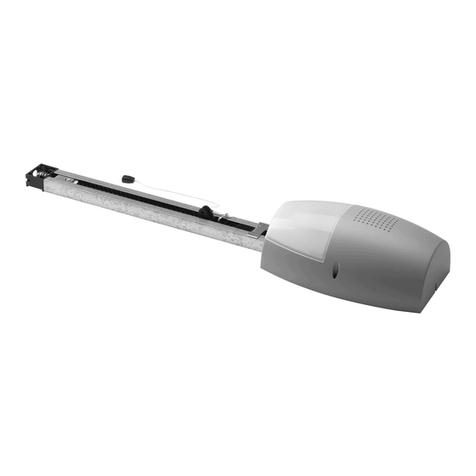
Table of contents
Languages:
Other BFT Garage Door Opener manuals

BFT
BFT BOTTICELLI BT A 650 User manual

BFT
BFT SP 3500 User manual

BFT
BFT deimos ultra bt a 400 User manual

BFT
BFT DEIMOS ULTRA BTA400 User manual

BFT
BFT EOS 1200 U User manual

BFT
BFT KR92522800003 User manual

BFT
BFT BOTTICELLI VENERE User manual

BFT
BFT BAT User manual

BFT
BFT BOTTICELLI SMART BT A 850 User manual

BFT
BFT EOS 120 VENERE D User manual
Popular Garage Door Opener manuals by other brands

Real Carriage Door & Sliding Hardware
Real Carriage Door & Sliding Hardware Edison Sliding Opener installation manual

Auto openers
Auto openers Roll Master instruction manual

Chamberlain
Chamberlain Logic 5 quick start

Chamberlain
Chamberlain LM60K-MB instructions

Seip
Seip A 45 installation instructions

Beninca
Beninca BULL 5M.S manual