Bianchi 1885 User manual

Assembly Manual
Road Bike

Assembly Manual Road Bike
2
Assembly Manual
Road Bike
I. Unpacking the box 4
II. Getting the front wheel ready 4
III. Fitting the front wheel 5
IV. Fixing the front wheel into the fork 7
V. Adjusting the handlebars 7
VI. Fitting the saddle 8
VII. Fitting the pedals 8
VIII. Test run 9
IX. Bike maintenance guidelines 10

Assembly Manual Road Bike
3
Dear Customer,
Congratulations on the purchase of your new bike.
With the aid of this Assembly Manual you will be able to
complete the assembly of your road bike / cyclo cross bike in
your home in a couple of steps. All of the necessary assembly
work and pre-adjustments to the gears and brakes have already
been done by our bike tters.
You only need to straighten the handlebars, t the front
wheel and t the saddle and pedals. All of the tools
needed to t these components can be found in the
accessories box enclosed.
Important: It is essential that you also read the manufacturers’
own operating manuals to fully understand all of the technical
features of your bike.

Assembly Manual Road Bike
4
I. Unpacking the box
Open up the special shipping box and remove the rectangular
protective cardboard on the rear wheel.
Take the wheel out of the box, followed by the saddle and
then the bike frame, which has the rear wheel already tted.
Remove the accessories box (Fig. 1)
Fig. 1
II. Getting the front wheel ready
Remove the two plastic protective covers on the hub of the
wheel
Open up the package of accessories and take out the quick
release skewer
Fig. 2 Quick release skewer
A
B
C
D
Loosen the acorn nut (B) on the quick release skewer and
remove the springs (C)
Insert the quick release skewer with the spring (D) into the
hub axle (Fig. 3 and 4)
Fig. 3 Fig. 4
From the other side replace the second spring (C) onto the
skewer and gently tighten the acorn nut (B)

Assembly Manual Road Bike
5
III. Fitting the front wheel
Once the front wheel is ready to be tted into the fork, proceed
as follows (depending on the type of brakes):
Important: Get a second person to help you when tting the
front wheel or alternatively use a bike stand.
Remove the plastic protection from the fork dropouts (Fig. 5)
Fig. 5 Remove protection from the fork
a.) Wheel with calliper brakes
Lift the mountain bike by its stem with one hand
Open up the adjustment lever so that it is pointing upwards
(Fig. 6)
Fit the front wheel in the direction it is to rotate
Fig. 6 Fig. 7
Close the quick release skewer on the hub of the front wheel -
more details about this under Point IV
Close the adjustment lever on the calliper brakes once the
wheel has been tted, so that it points downwards (Fig. 7)
Important: Make sure, when tting the front wheel, that the
fork dropouts are sitting completely on the axle!
Attention: Check that the front wheel is rotating freely. The
wheel has not been tted properly if the wheel is not running
straight or if the brake is clearly rubbing!

Assembly Manual Road Bike
6
b.) Wheel with cantilever brakes
Lift the cyclo cross bike by its stem with one hand
Fit the front wheel in the direction it is to rotate
Close the quick release skewer on the hub of the front wheel -
more details about this under Point IV
Important: Make sure, when tting the front wheel, that the
fork dropouts are sitting completely on the axle!
Now t the cantilever brake by pressing together both calliper
arms with one hand so that the faces of the brake pads sit at
against the rim of the wheel (Fig 8)
Using the other hand, pull the cable towards the right-hand
brake arm so that the cable tting can be connected to the brake
arm (Fig. 9)
Fig. 8 Fig. 9
Attention: Check that the front wheel is rotating freely. The
wheel has not been tted properly if the wheel is not running
straight or if the brake is clearly rubbing!

Assembly Manual Road Bike
7
IV. Fixing the front wheel into the fork
Close the quick release skewer by rotating the lever by 180°
(Fig. 10 and 11)
Fig. 10 Fig. 11
Attention: If the quick release skewer is correctly closed, the
word “Close” should be legible on the outside of the lever!
Attention: When tightening the quick release lever (A) it should
meet resistance at about the halfway point. Otherwise you will
have to increase the tension using the acorn nut (B) on the
opposite side of the hub! (c.f. page 2, Fig. 2)
V. Adjusting the handlebars
Use the multifunctional tool supplied.
Select the correct Allen key to loosen the stem locking screws
on the handlebars (Fig. 12)
Once you have adjusted the handlebars to suit your position,
tighten the locking screws on the front cross-wise.
Make the necessary adjustments to your handlebars. Make
sure that the handlebars are centrally aligned in the stem clamp
(Fig. 13)
Fig. 12 Fig. 13
Attention: Make sure that there is an even tightening torque on
all of the stem locking screws. The clearance of the stem clamp
has to be identical, otherwise there is a risk of a serious material
defect on the handlebars!
Assembly Manual Road Bike
8
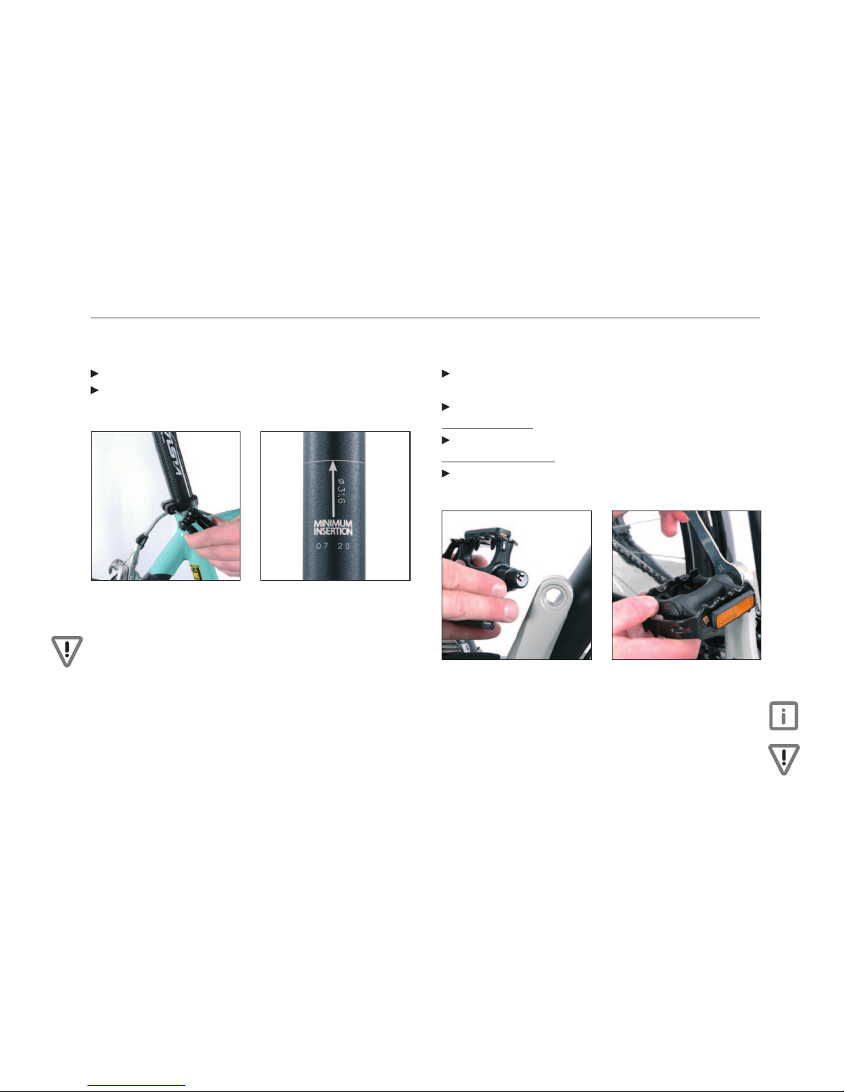
VI. Fitting the saddle
Use the multifunctional tool supplied.
Insert the seat pin into the seat tube and adjust the height of
the saddle (g. 14)
Fig. 14 Fig. 15
Attention: Ensure when adjusting the height of the saddle that
the seat pin is not pulled out further than the maximum height!
Failure to comply with this can result in serious material defects
or accidents! (Fig. 15)
VII. Fitting the pedals
Take out both pedals from the box of accessories, should they
have been ordered.
Identify the right-hand pedal and screw it in a
clockwise direction to the right-hand crank (Fig. 16)
Screw on the left-hand pedal in the same way in an
anti-clockwise direction to the left-hand crank
Tighten both pedals with a 15 mm spanner and, after a few
miles, check once again that they are still tightly tted (Fig. 17)
Fig. 16 Fitting the right-hand pedal
to the right-hand crank
Fig. 17 Tighten the right-hand
pedal in a clockwise direction
Important: The right-hand crank is always on the side of the
chainset.
Attention: Failure to note the markings on the pedals or tting
the pedals with force will inevitably damage the threads!

Assembly Manual Road Bike
9
VIII. Test run
Your new road bike is now ready to ride and you should take it
out for a test run straight away. (Fig. 18)
Fig. 18
Important: Before heading out, check once again that all of the
screws and quick release ttings are tight on your bike.
Important: In your own interest, we would recommend that
you have your bike inspected after approx. 100 km. Bikes cannot
always be correctly adjusted without a certain period of runnin-
gin. Mechanical components, like brakes, gears and bearings
have to be checked and readjusted after a certain time.
An initial inspection by qualied technicians will guarantee that
your bike has a long life so that you can enjoy unlimited cycling
enjoyment.
Important: Keep a note of your frame number! The frame
number is generally located on the bottom bracket – the position
may vary with different manufacturers (seat pin, head tube). It
is easiest to note down your frame number on the invoice for
your bike.
Attention: Road bikes, which do not have lights, do not comply
with the requirements of § 67 of the German Road Trafc
Licensing Regulations (StVZO). Please be aware that these
sports bikes are not permitted to travel on public roads.
Attention: It is essential that you also read the manufacturers’
operating manuals to fully understand all the information and
technical features of your new bike.

Assembly Manual Road Bike
10
IX. Bike maintenance guidelines
Attention: The rst inspection should take place after around
100km i.e. 6 weeks. Screws are to be tightened and cables
should be adjusted accordingly.
Important: Inspections should be carried out regularly (after
100km i.e. 6 weeks, after 500km i.e. 6 months, after 1000km
i.e. 1 year, after 2000km i.e. 2 years, and then once a year).
Have fun with your new bike!

Assembly Manual Road Bike
11
Space for notes:

Table of contents
Other Bianchi Bicycle manuals


